
RoboArm
A robotic arm that has 2–3 hinged segments moved by servos or tendons, controlled by a microcontroller and EMG sensor for mind-control.
Total Time spent: 51.5h
July 18th:
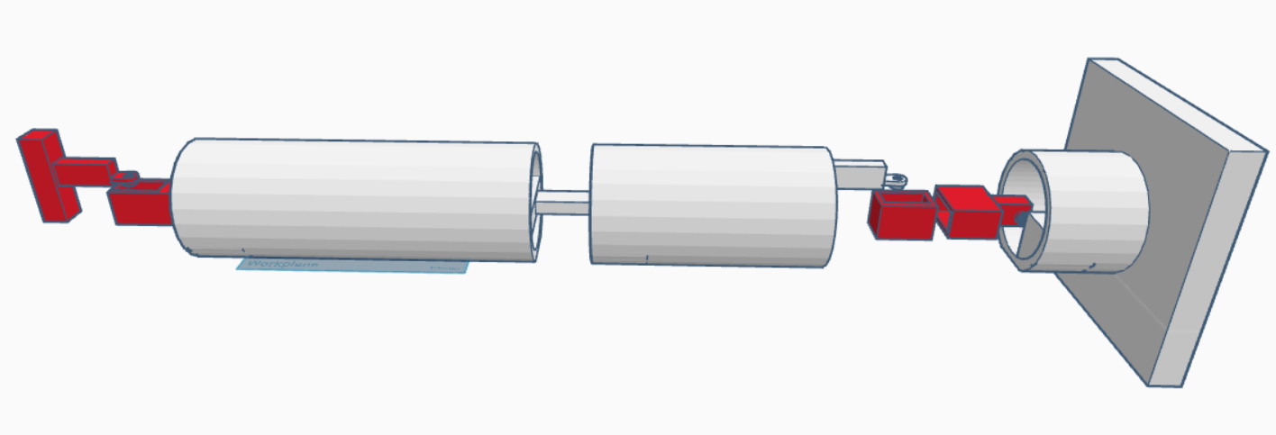
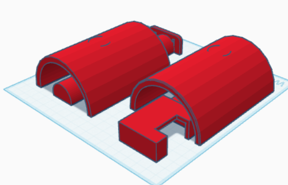
I worked on my CAD. I had to really think about how to design the arm. I decided to start off with some cylidners and then processeded to hollow them out, cut them, connect them, then added servo motor holders I think thsi is a good general structure, but I'll have to measure the mount position on a servo motor to exactly determine the positiosn I would put it in the real world. I also need to check how much the servo motors would be abe\le to rotate at the crrent positions.
Time spent: 2.5h
July 21st:
I worked on my CAD. First of all, I copy-pasted the RoboHand I made in a previous project just to see how it would look. Then, I realized the hand was too big, so I measured my own hand's fingers and dimensions in order to apply that to the CAD. I also moved everything closer so it fit together. I realized I had to add covering for every single part, so I did that, and had to adjust the dimensions of the white cylinders of the arm because I realised most of them were too big. It was difficult trying to make space for the servo motors, and probably will be even more difficult, because I realised I need to add more servo motors to the hand itself, since it needs to be able to move all the fingers very freely. I also realzied I need to make the right ends of the cylinders circular and then make their left ends have a circular cutout, so the joints can move nicely.
Time spent: 2h
July 22nd:
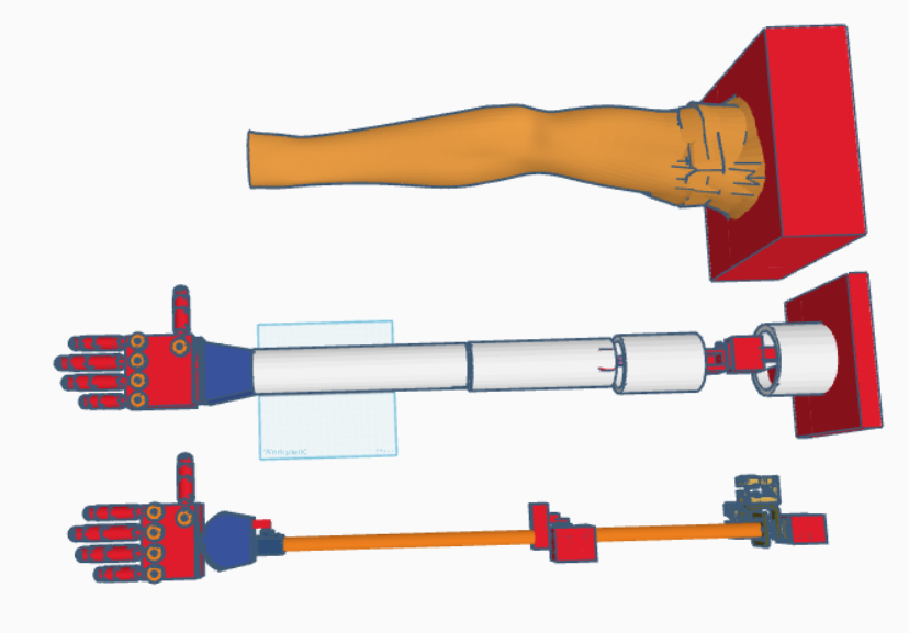
I worked on my CAD. I first made a literal human arm within the CAD which was done through using scanned arm models and then converting them to STL files and then hollowing them out while also removing the extra stuff around them. After that, I decided to work on modeling exactly what the servo motors and inner components of my RoboARM would look like, because my previous version (the arm in the middle) felt too inefficient and also didn't satisfy everything I wanted to. Instead, one of the major improvements I did was build a 3-axis gimbal at the base of the arm which I made following a tutorial. After researching I decided to use Dynamixel motors for the gimbal and the elbow. Then, at the wrist, I had to also change the motor to a standard MG90S. These motor changes required to change the casing that would contain the motors. Anyways, for the wrist, I had to also make a curved cutout the blue wrist/palm part because I accounted for the hand's actual yaw movement. Everything in total took so much time because I completed multiple tasks, which all required detail, like the arm, the gimbal, and figuring out my exact components, getting their dimensions and their horns.
Time spent: 6h
July 23rd:
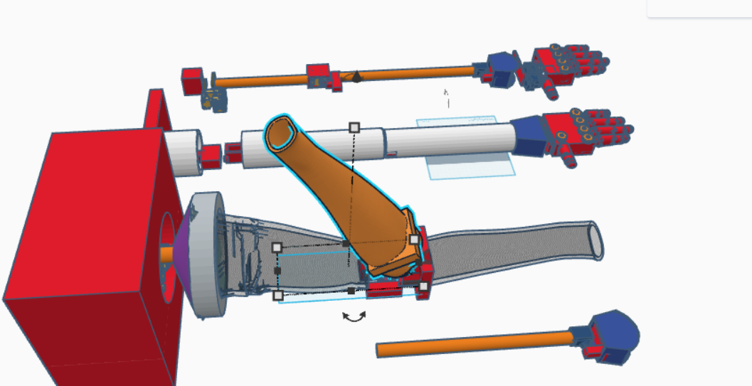
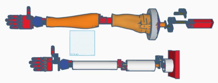
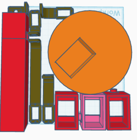
I worked on my CAD again. While the image looks messy, all it really is that I merged the revised components
version of the arm (at the back) into the actual human arm model. I had a lot of trouble with the gimbal because the little stage in the middle was too small to contain the whole arm. Moreover, the motion of each of the servo motors in the gimbal have their own area/circle of movement so I had to estimate that, then make cylinders of them, to then cut out of the big red base box. I was also in general trying to figure out how the big arm would fit on the stage, and in the end, finalized on a tube + cone that connects the stage to the arm. Then, I moved on to the elbow which also surprisingly took a long time. I had a lot of trouble actually figuring out the proper position and attachment method for my servo motor to act as a hinge. This was because I really wanted the arm to be a fully enclosed and connected thing like how it is in the real world, but when you move the arm around the hinge, it would get stopped
by the bicep part. I'm still not satisfied with what I decided to do (which was just leave a space at the hinge for the servo motor, so the arm could move a full 120 degrees which is what the orange arm is showing).
Moreover, if you look at the component
arm at the back and look at the hand, I changed the hand quite a bit. I had to significantly shorten it and I also was trying to figure out how to give the thumb 3 DOF movement, but I realized that the servo motors wouldn't be able to fit. I'm not done with the hand, but technically, that was for another project, and the 3 DOF isn't completely necessary, so I don't need it right now, but I still spent time on it, because the thumb movement is very important for a proper human hand. Most robotic hands don't have a 3 DOF thumb because of these problems, but I will eventually fix that.
Time spent: 6h
July 24th:
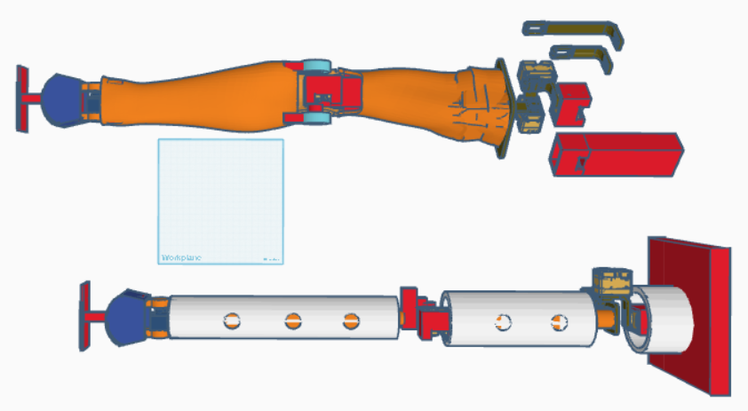
I worked on my CAD again. I think I've finally finished. Basically, I realized that the gimbal was really messed up, and it still is. I tried moving the bicep part around each of the gimbal's servo motors and I realized that the bicep was going to be stopped by the servo motors, especially the bottom (far right) motor because the arm is very big and wide. So I had to extend the connectors of the gimbal for almost each servo. I'm still not sure if it would work, but I do know that even if it doesn't completely fit the whole range of a human arm, it will still be able to complete a majority of it. Anyways, the wrist part was relatively simple, I just had to move the components to the human arm's wrist, then adjust the servo motor so it wouldn't waste too much space.
Then, I decided that I want an actual more simplistic and straightforward robotic
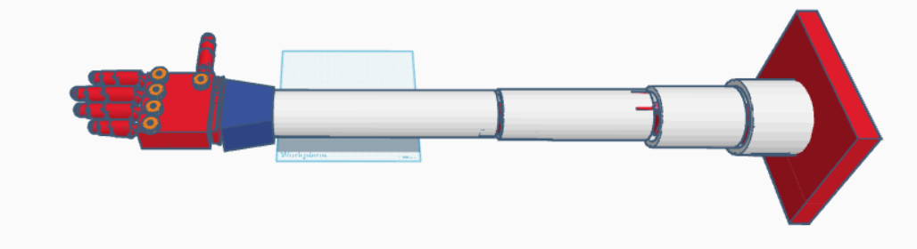
arm version, instead of the realistic human arm version as well. So, I just duplicated the white cylinders of yesterday's middle arm (the original arm that I built which was bad), and then put it around the orange cylinders. I then had to fill it in, so they would actually connect, and also made sure to shorten the cylinders accordingly so they wouldn't interfere with the realistic movement amount of the arm.
I think tomorrow, I'll work on separating the parts and fixing anything else I notice.
Time spent: 5h
July 25th:
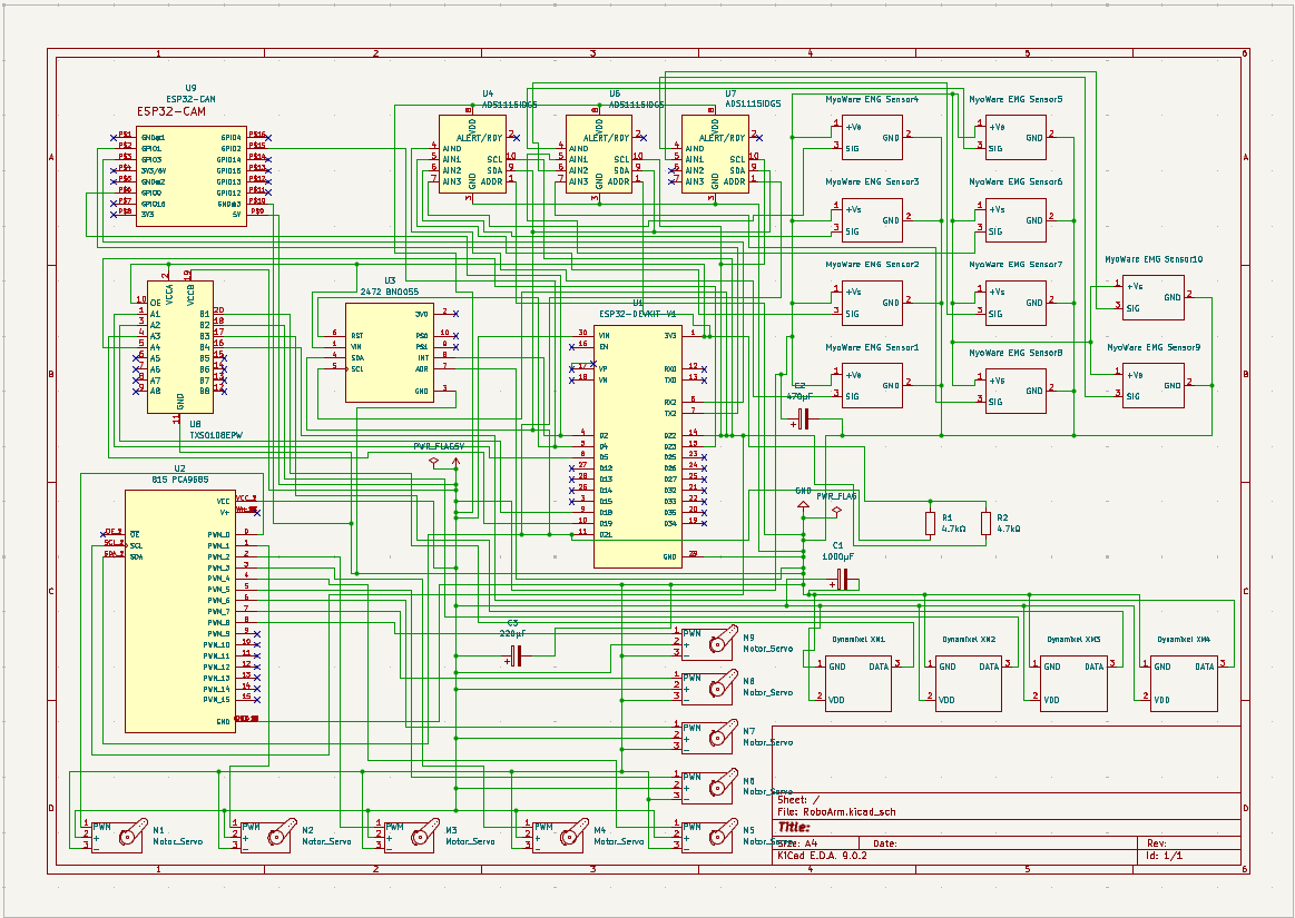
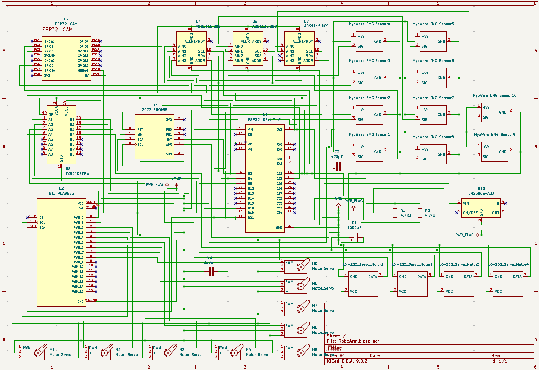
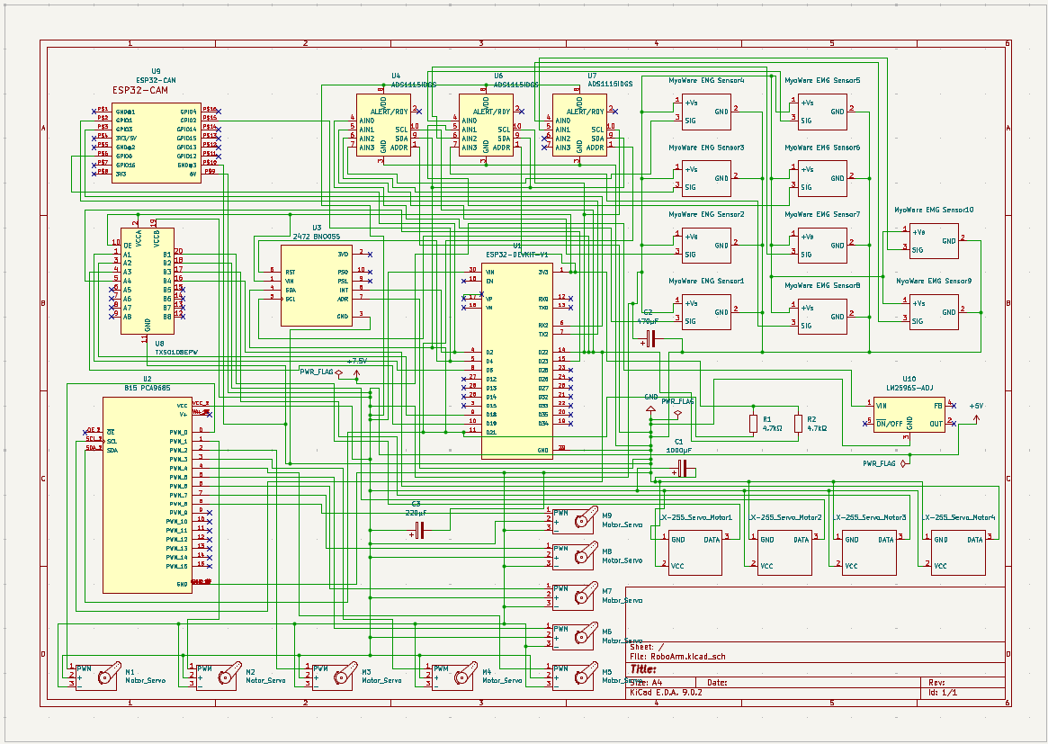
I worked on my circuit schematic. It was extremely confusing because some of the parts I neededcl ike the Dynamixel servo motors and the MyoWare sensors didnt have any footprints of symbols, so I had to make them myself. Moreover, I had trouble getting the correct BNO055 and some of the symbosl like the ESP32-CAM had errors for their pins. They had Bidirectional as the electircal type for all of their pins, which is completely wrong because power pins like the 5V and the GND pins should be power input. Also, as I moved the components over everywhere, some of the wires got into unwanted junctions and stuff which was very very annoying to fix. There were also a lot of errors on the ERC so I had to track everything and fix it. There were so many components that I had to research how to connect and then manually connect everything as well. Since I'm a beginner at KiCAD, it took so much time to fix all of this. And then I realized I had to add resisotrs forth e SDA and SCL lines, and capacitors for the motors, ADS1115s, and MyoWare sensors. After this, I decided to not use a PCB, because first of all, my components need to be spread out over the hand and arm, and also I will need to be careful to make sure the connections are actually correct IRL, so I'll manually solder everything. I think the schematic is mostly done because I made sure all of the connections made sure by verifying what other youtube videos have done.
Time spent: 4.5h
July 26th:
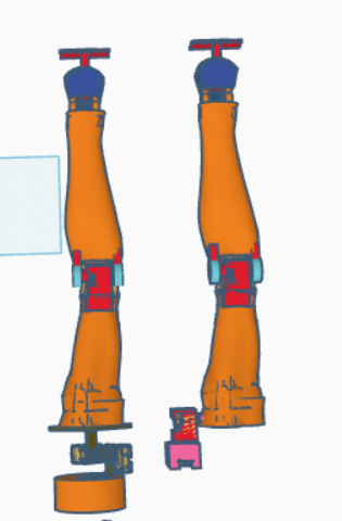
First, I worked on my schematic, because there were still some library issues related to the downloaded parts like the PCA8095, the BNO055, and the ESP32-DEVKIT-V1. For some reason, the ESP32-CAM was working fine, so I was trying to figure out why that was workign and not these ones. After checking online for others who had the same problem, I finally realized that it was somme very tricky pathing error that I had to scour to determine how to change it (TLDR, it wasn't as easy as just updating the symbol and footprint library paths). Anyways, this part took way too long. Nothing in the circuit itself was changed, except for replacing these three components after a bunch of trial and error stuff, but the component is still the same, just the path is different. Then, I worked on my CAD. I first removed the hands because I realized that I needed to focus on only my arm right now, and not the hand, which was already technically finished. I mainly focused on fixing up the human version of the arm because it was wayyy too big and it likely wouldn't have worked properly before because of the large size and weight. Rather, I first took measurements of my own arm and then scaled the CAD to that yet slightly larger. I also change my hinge joints at the elbow and the wrist by adding circle attachments instead so that it would rotate equally and was easier to test to see if it would rotate properly. I added a cutout on the bicep so that the upper-part of the arm could move its 120 degrees. I had to also fix/erase the extra unwanted sticking out parts when a rectangle piece was sticking out the tubes. I also added the wire cutouts for the Dynamixel motor because I seem to have forgot it before. The MG90S motor already has a wire cutout so that one is fine. It took a lot of time fine-tuning everything so it actually looked good, and also testing everything such that I could achieve a satisfactor amount of freedom movement angle. I'm still kind of worried about the human arm version because now the gimbal's stage is very big and I dont know how to will rotate with the arm + hand as such a large mass. Moreover, I feel like balance will also be an issue. I think I might need to scrap the human version of the arm or atleast put it aside as not my main casing because I'm unsure that it will work properly. That's why I have the human and robot verisons anyways, because I could choose one and work on the other later. Anyways, I'm almost done. I just need to separate the separate parts into CAD which will take time, and then I need to work on my README/BOM.
Time spent: 6h
July 27th:
First, I worked on my CAD. I first added a base to the human arm thing, because even though originally I was thinking of just clamping the bottom servo motor IRL, I realized that in testing, I'll need multiple situations and positions and clamping might not be the best way. Additionally, as I was doing that, I decided to try out a different 3 servo motor gimbal design, where it was focused on being compact. It's essentially just three servo motors directly attached to a servo motor (except for one of the servo motors of course), rather than using attachments/mounts. This took some time figuring out and placing the arm so I could find a good position to keep it from hitting any of the servo motors when rotating. I even tried posing it IRL. In the CAD, I decided to place the servo motors where the armpit would be, because my end goal of my next few projects will be to construct a full humanoid, so I would need the arm to be able to connect to a shoulder or torso, and not a flat base. Anyways, after that, I chose to first check all of my CAD to make sure I had everything. I noticed a small error that some of the pieces were not connected or misplaced. Then, I started separating my robotic arms into multiple CAD files, which resulted in a lot of CAD files, especially since I have two models of arm which are the Robotic Arm and the Human Arm. During this, I decided to smoothen and polish up some of the CAD since I got to have a closer look at every piece. Finally, then I started working on my BOM which took SO LONG. I have so many parts so it makes sense. I had to make sure every product I found was the correct one, was the cheapest, consider shipping, and also consider the reviews. Moreover, I realized that the Dynamixel servo motors and the MyoWare EMG sensors are wayyy too expensive. Tomorrow, I'll probably check up on some alternatives, edit the schematic and CAD, and then recalculate the BOM. In the BOM, I also remembered to reduce the number of MG90S servo motors from 9 to 2, because we aren't including the hand within this project. That’s when I realized I had to also edit my schematic to have two versions, one with the hand's servo motors (just had to remove the 7 servo motors because IRL, I'll need to connect all servo motors anyways, so all the other components will be needed), and one without. I'll upload all of the CAD files tomorrow after I'm done updating.
Time spent: 6h
July 28th:
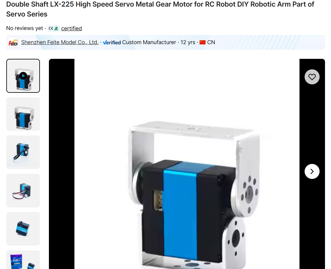
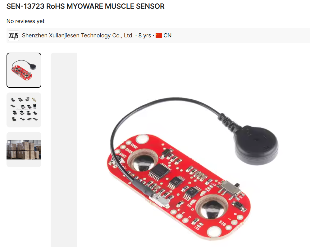
Like I said yesterday, I just focused on finding the correct and best replacements for the Dynamixel servo motor and the MyoWare EMG sensors. I first made up a list of a few different decent replacements for each one by checking reviews/posts. Then, I searched each one and filtered out the ones that were too weak or too expensive. I finally was able to find two possible replacements for each of the Dynamixel and the MyoWare. I found an LX-224 and an LX-225 for the servo, and I found a potentially cheap MyoWare 1.0 and a cheap ECG (not EMG unfortunately) sensor that's often used with Arduino. After messaging the customer service people for each component and also deciding between my choices, I've locked in the LX-225 and the MyoWare 1.0, because the LX-225 offered more torque for about the same price and size as the LX-224, and torque is especially important because the Dynamixel has 40 kg*cm, so I need any torque I can get. For the MyoWare, it was mainly decided due to the fact that it wouldn't change any of my schematics and moreover, the MyoWare is genuinely good quality, has a lot of good documentation, and doesn't need any extra parts like a shield for example. I had to scour a bunch of different options on various websites like RobotShop, Amazon (even though there weren't any unfortunately), and Alibaba/AliExpress. I researched and I will likely need to update my schematic because the servo motors need a DC buck converter. I will also need to update the CAD servo containers because of them. I started some of that today, but didn't get to finish it, so I'll leave it for tomorrow.
Time spent: 2h
July 29th:
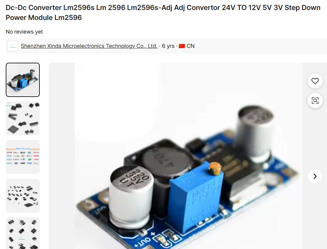
I finished updating the circuit schematic and the CAD. It took some time picking out the right DC buck converter, becasue the first one I used, was wayy too complex for me, but the second one was good because it had a bunch of simpler connections and also had some inbuilt stuff. I had a few errors related to the input and output power pins, and unfortunately I sitl lwasnt able to address one because KiCAD needs to have a PWRFLAG for the OUT pin on the DC Buck Converter so thatit can be recognized as a power source, but because the OUT pin is an Output pin and the PWRFLAG is a Power Output pin, they can't be connected, so I'm not sure hoq to fix that. I even asked on Slack, but no one knew how to fix it.
Time spent: 1.5h
July 30th:
I received updates from the people from Aliexpress and unfortunately the MyoWare sensors that were priced at $10 are not in stock, which means I need to look for other options. So, I first searched up again on other sites like Alibaba and robotnot but most of them had terrible prices. I found one potential MyoWare 1.0 sensor priced at $30, which is still expensive, but it is definitely the cheapest one considering shipping as well. However, since they are at $30, I will barely be able to get 5 or 6 sensors. After researching, I found that I do not NEED 10 sensors, however, for fluid human-like motion, it is definitely extremely useful. I'm thinking of replacing some of the lack of data using datasets online too if possible or ask universities in my area to borrow their cheap sensors for testing. It's desperate, but I need at least these 5 or 6 sensors. For 6 sensors, I need to probably take out the MG90S motors, the ESP32-CAM, the capacitors, the pull-up resistors, and the shipping out of my BOM, because if my RoboHand project gets approved, then I should be able to acquire those items. This means that I will need to also delete 4 sensors out of my schematic. I just chose not to reduce the EMG sensors in my schematic from 10 to 6 because in the future, when I do buy the other 4 sensors out of pocket, I want to be able to use the 10 EMG sensor schematic easily, which is why I have not changed it to have 6 EMG sensors. Additionally, to fix the error that I had with the DC Buck Converter, I simply added a +5V power symbol and deleted the wire connection from the OUT pin, because the OUT pin will produce 5V anyways, so it’s fine if I replace it like this. There’s also no error if I do this. I also edited the CAD servo holders as needed. It took some time because I had to also edit the servo mounts/attachments since all of the Dynamixel's attachments need to be converted into the LX-225 version. Next, I need to work on the firmware. To do that, I need to look at some tutorials and research papers and GitHubs properly to understand how to build a good EMG and other modalities dataset. I can also prepare a basic model template for the ROS, but it'll be difficult. I took down some notes as well, and a basic plan structure.
Time spent: 3.5h
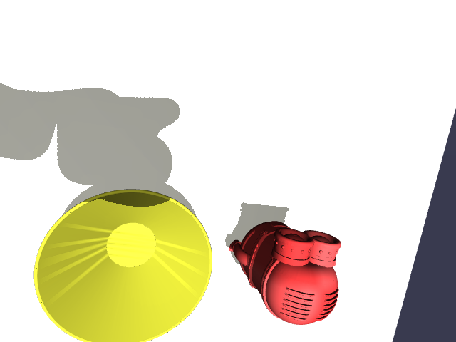
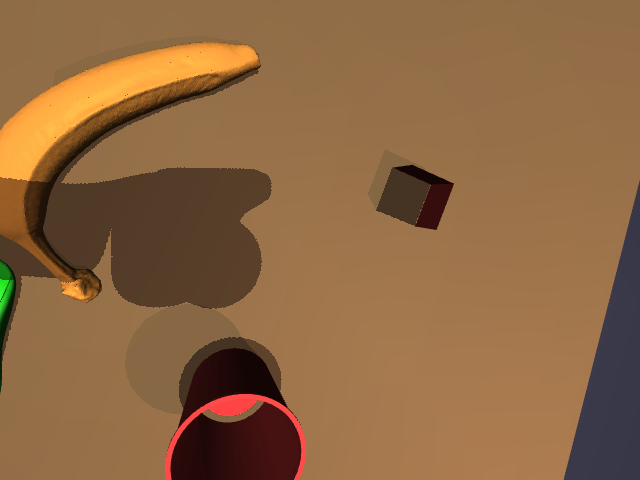
July 31st:
I read more research papers on my robotic arm, how to make it have human-like fluid motion, how EMG sensors work, previous projects and tutorials about EMG sensors, alignment with other modality inputs, processing EMG data, and making a model using it. Since I don't have my parts yet, I can't test anything, but I just wrote up some basic scripts of how the general pipeline should look like. I based off the realtimedata.py code off of what other research papers and GitHubs did to custom align the modalities, which was actually much simpler than I imagined. Basically, all you need is to make the microcontroller send a signal to all of the modalities at the same time to start recording, and then also have proper timestamps. I was also able to make a fake dataset for the models.py code and then test the functionality using that. It basically produced some garbage correlations and understanding since it was fake data, but at least it worked after a few hours of work. I chose to perform data processing, then use LSTM and RL models to actually learn from each of the modalities, make a model for each, then make combination models, and then test accuracy and stuff for each one. I also looked into what other previous papers did for the camera/visual-based hand motion, and even worked on constructing a dataset for that today. I used MuJoCo simulation to write up a code that can actually construct a dataset from various viewpoints, and used a Kinova Gen 3 arm (which is good for beginners to work with) to simulate different object placements and arm positions/configurations. I initially tried to use random arm configs to get different arm positions, but it didn’t work, so I decided to use some simple Inverse Kinematics (IK) to move to different points in the space around the arm. That worked out better, but then I had to work out the camera alignment which took a lot of time to fix. I first tried out just doing trial and error for each camera alignment shift and seeing its trajectory to the target objects on the table. Speaking of objects, I downloaded a few free STL objects from online and then used that in my simulation to generate my image dataset. I also realized that I forgot to add my DC Buck Converter onto the BOM, so I added that, by searching up stuff online. Then, I realized that ideally all my products should be from Aliexpress because it often has the cheapest deals... So, I had to spend another few hours scouring Aliexpress, Alibaba, and Amazon (just to make sure) so that my products were truly the best and cheapest deals, even if they came late. Atleast, I learned something through this, that I should be careful and always try to save money. After doing all of that, I converted my BOM also into a .csv file, and then rechecked everything just to be sure, before I submitted.
Time spent: 6.5h