
Thrust FPV stunt drone
a visually stunning FPV Stunt drone, with a custom FC
TOTAL HOURS: 24
DAY ONE
The drone should have the following qualities: - Small - agile (speed and quick turns) - have a custom FC - cameraaa - be resistant to crashes (or be designed to break in a way that it can be reassembled) - be under $150 - look polished and visually striking (hoping to win highway design competition :3) - self stabilised
I also need to somehow make it in 3 days to be eligible for the competition :heavysob:, but i'm still gonna make it good
Today I'll start the flight controller PCB. I was confused between using STM32F4 chips (used most commonly in drones, great perfomance) and RP2040 (slower, but easier to setup). ChatGPT said STM32 chips are significantly harder to setup initially, but post talkuing to a few people on the slack, STM isn't too hard to setup, so I'll be using the STM32F401CCU6 with USB FS and STMDuino support.
DAY TWO
Made most of the schematic today
This is mostly the low level stuff for the STM32 chip to work, and added ICM-42688-P. I'll be using an ESP32-CAM module for the camera and wireless connectivity. The camera is fully independent of the STM32, and a UART connection between ESP and STM32 is used for controls.
I don't think I'll be able to submit for the design competition :sob:, but that gives me more time to work on a well designed, high perfomance drone with a custom FC.
Tomorrow, I'll get started on BOM (battery, motors, ESCs, etc), and hopefully also finish the PCB!
Schematic: 1.5 hours
DAY THREE-FOUR
Worked more on the schematic, and finally finished it!
It's not exactly neat, but I'll organise and label the blocks later (when i ship it).
Also, a problem i realised when going to make the PCB-- I didn't label the capacitors' and resistors' capacitance and resistance respectively :skull:, so it'll take some more time.
Schematic: 1.5-2 hours
DAY FIVE
So I'm almost done with PCB layout, it's quite compact for now but i need to consider things like noise and interference with RF and MCU, so that might take another day.
PCB so far:
Rounting seemed VERY overwhelming till now, but it was done like a breeze lol PCB: 1 hour
DAY SIX
Okay, PCB is almost fully finished, just need to route the RF module and GND plane. (The entire PCB fits under 4.5cm?!)
This looks SO complicated but im really proud of myself for building this and not picking up a good expensive FC from a website :D
I wanted to work more but I also really need to start preparing for an upcoming MUN in a week
PCB: 1.5 hours
DAY SEVEN
I got to work after a looong time because of exams, and then an MUN i had to prepare for, so I will be locking in to make this now. Completed the PCB :D, however I need to face my biggest fear now (DRC :sob:). Also, while designing, i figured that if the ESP32-CAM was attached to the FC, it couldnt look at the surroundings, so I decided to just have +5V and GND test points to connect it using wires.
PCB: 1 hour
DAY EIGHT
Today I started off with CAD, did some research and an unfortunate amount of time trying to understand mathematics of how a freestyle drone should be made, mostly looking at torque figure calculations. I was originally thinking of making a neat, aesthetic square-with-4-circles design. But after some research and looking at other designs, freestyle drones were almost exlusively of a shape called streched X
. This has something to do with moment of inertia and torque required to turn it. The pitch axis should have more t than the roll axis for a good, smooth, gliding
like feel. The arms of the drone create 'r', which is the perpendicular distance of mass from the center, and t is directly proportional to it. It shouldnt be too less (for stability), but not too long (to not increase torque too much). Also, when I started, I started off with the ESP32-CAM module-- until I found an analog, high quality actual FPV camera. I had previously hugely underestimated the latency of WiFi.
I worked on several designs and arm shapes and none of them actually looked good/practical. I got very tired of constantly reiterating, drawing, deleting, extruding, tracing, moving, etc so I'll do it tomorrow.
CAD, maths: 5-5.5 Hours
DAY EIGHT
A good decision I made was watching a few build videos to understand how frames are made typically, which gave me a surprisingly good amount of understanding. Also found some components (cameras, ESC, VTX, etc). In the end, I settled on an H-X Hybrid frame
(?) which I pretty much accidentally made. It co-incidentally looks similar to a deadcat frame too. A lot of CAD done, so I pretty much finalized it. Antenna mount, camera mount, screw holes, top, everything. I think it looks REALLY nice and unique. I plan on modifying the frame over the years as I get more knowledge and feel for freestyling drones; this is just MK1.
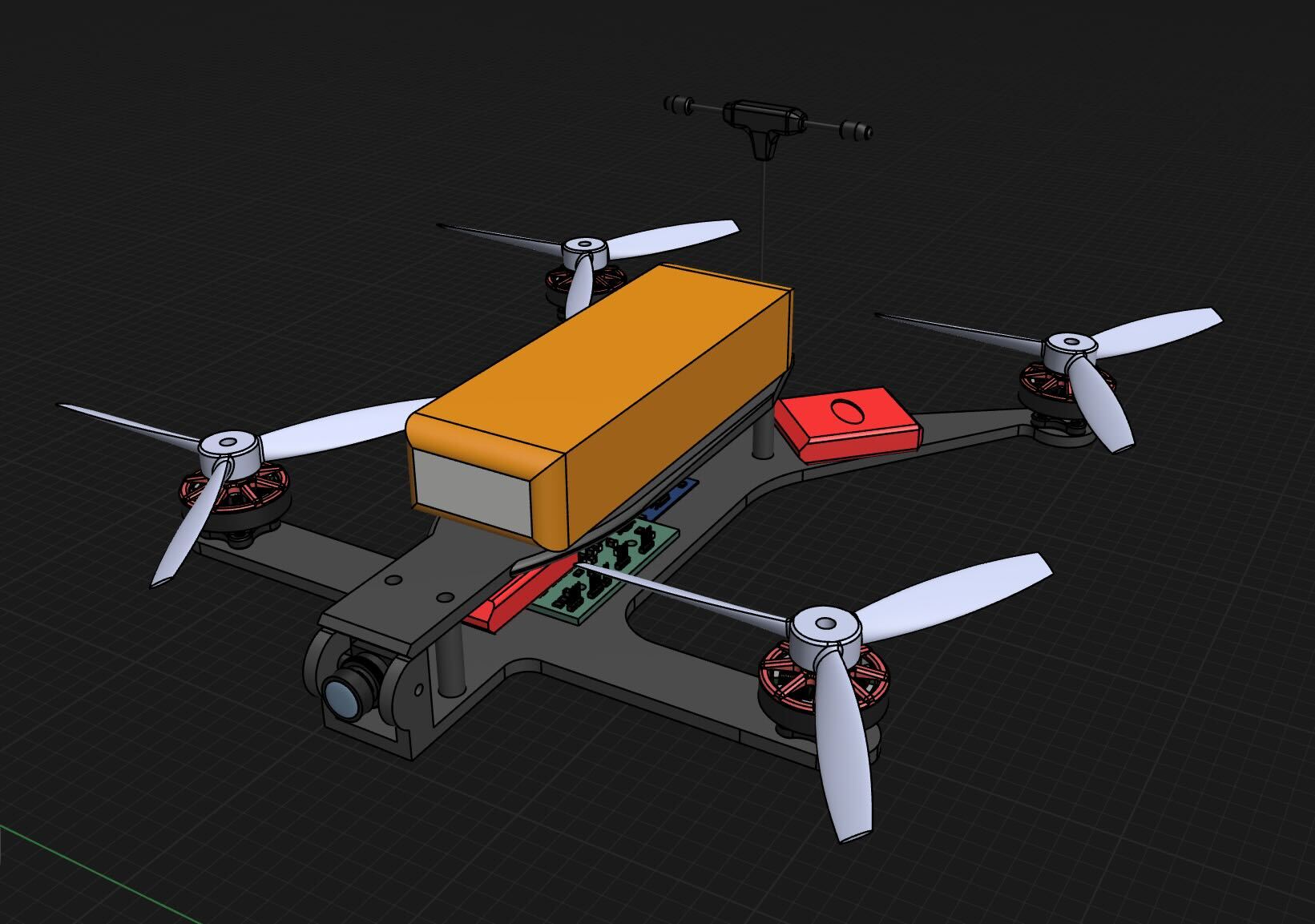
CAD, shopping: 6 hours
DAY NINE
The day I dreaded. DRC errors in such a complex PCB. Thankfully there weren't a LOT of hard-to-fix errors, but mostly about clearances and tracks not being connected to the STM32 (different layers), which was a CHALLENGE. it was so damn hard to reroute all the wires across 4 layers, try to fit a via somewhere without crossing lines :sob:. I also added 4 holes strategicaly to fit the ESC in a stack with the FC, which required me to reroute and reposition some components.
This image is the definition of
pain
:sob:
Anyways, it felt VERY good finally being done with the PCB-- finalized and fixed all DRC errors.
my beautiful beautiful son 🥹
PCB: 2.5 hours
DAY TEN
So the drone is pretty much done, just have to submit it now-- or so I thought. The BOM turned out to be ~7k INR more than the budget (💀), even though I only used reasonably priced components. Guess tomorrow will be for cutting costs :sob:
Research and BOM: 2 hours
DAY ELEVEN
Okay, so somehow I got the entire thing under the budget, using super cheap generic SimonK ESCs instead of the 4-in-1 ESC costing ~3k, replacing the holybro atlatl VTX with a cheaper VTX as well, and using a cheaper dipole antenna (since lollipop was overkill), and a significantly cheaper HC-12 RF module instead of the RFM69HCW. So haven't cut any functionality, maybe reduced ease of assembly and less beautiful, worth ~7k easily tho!
Submitting now! Massive thanks to hack club and the organisers of this YSWS-- its absolutely awesome!