
Velocis
Ultra Fast CoreXY auto ejecting 3d Printer
Project Velocis
Author: Euwain Sheard
Description Ultra Fast CoreXY auto ejecting 3d Printer
Total time spent: *17h*
May 24 (Day 1): Started CADing and Part Sourcing
I started by looking at various parts and how they would fit into my project. This is what I decided on so far
| Part | Price |
|---|---|
| Phaetus RAPIDO HOTEND | $80 |
| Octopus Pro | $70 |
| Orbiter v2.5 | $50 |
I might change this later, but I like these parts
Now to Cad! I have taken inspiration from the Voron Trident for the design of the frame and triple lead screw z axis
Picture of the cad
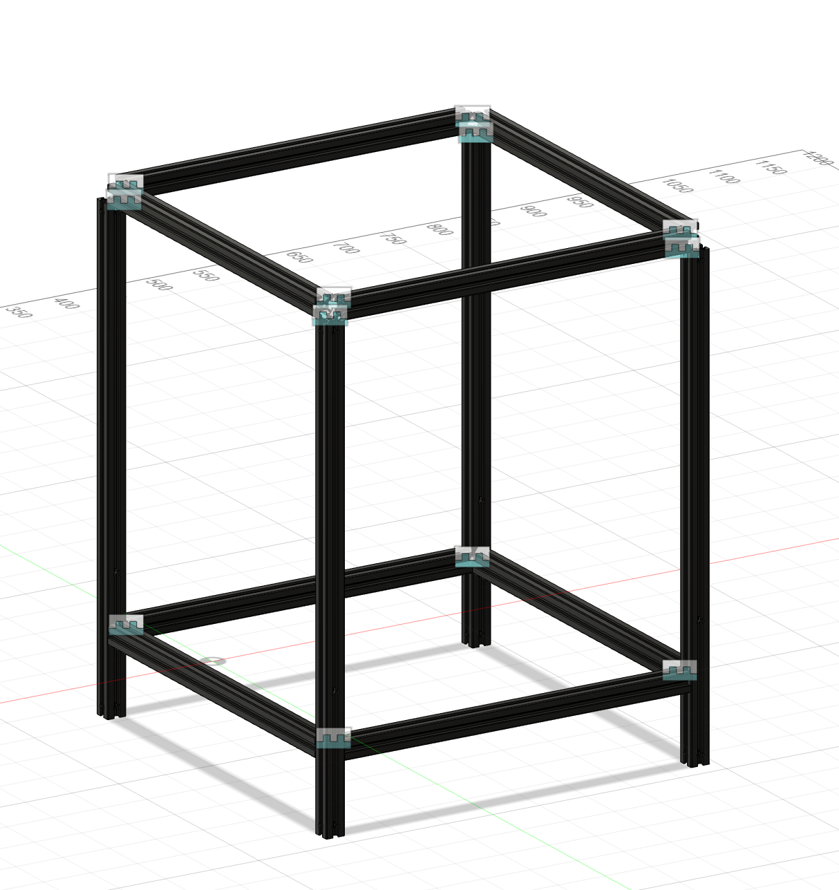
I am, however, having trouble with the extrusion files I found...
Time spent: 2h
Day 1 Part 2
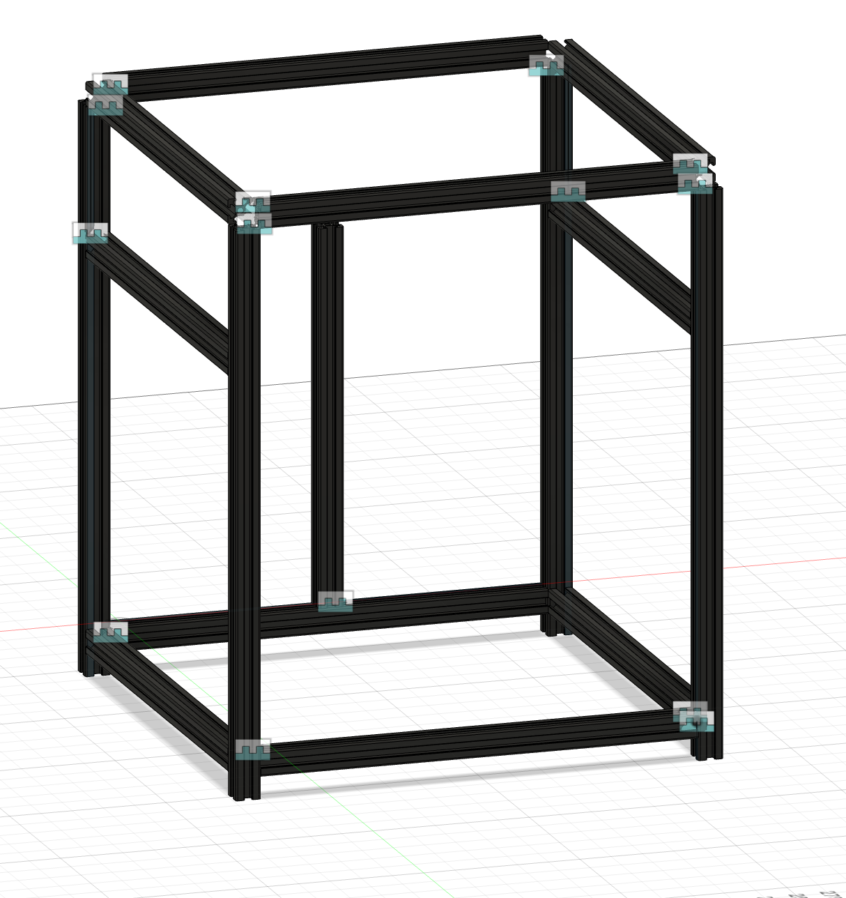
I worked on the Cad some more. I fixed the extrusion problems by uses these files instead. However this meant that I had to redesign the frame. When I redesigned the frame I decided to change some of the extrusion lengths. Now instead of 370, and 500, I shortened the extrusions to 350 and 450. I also modeled some of the x, and z gantry. I also organized some of the components, mainly the extrusions, into folders. I am going to use a mixture of Fusion 360's internal and external component options.
Updated Picture of Cad
Time spent: 1.5h
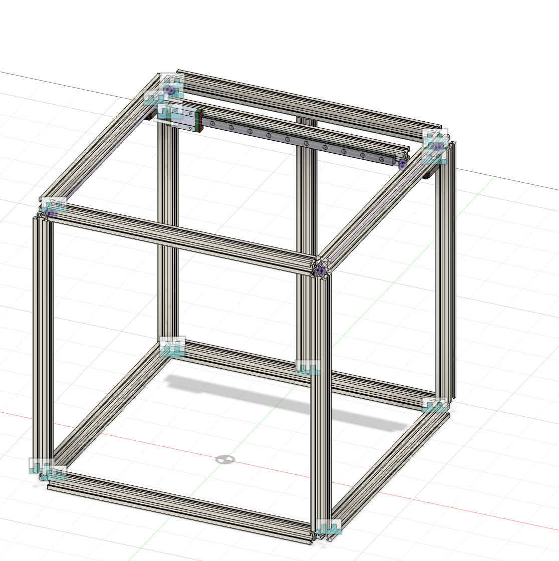
May 25 (Day 2): Cad
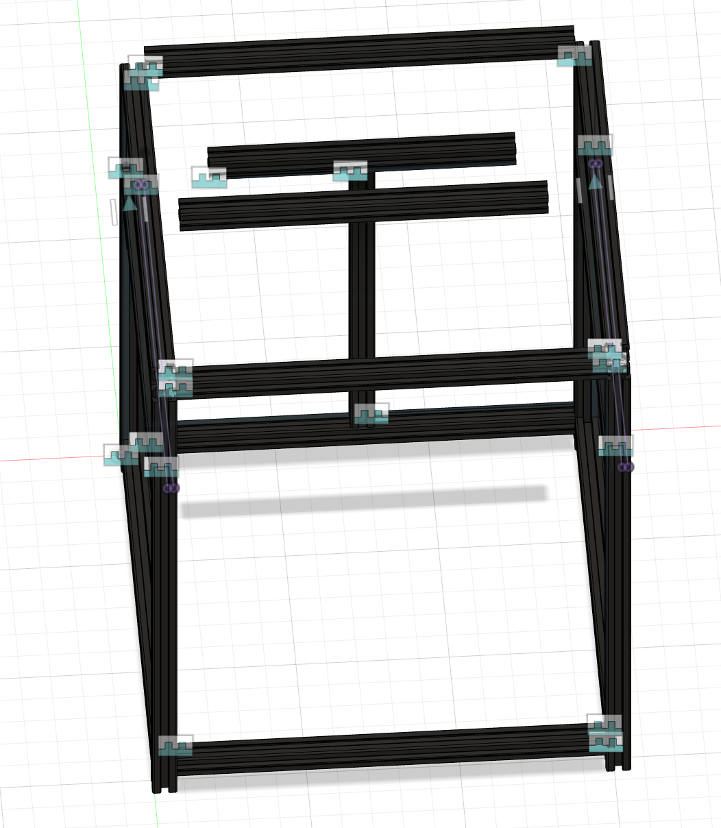
I started today by finishing CADing the basic frame, and looking at various linear rails. I found these on the Voron sourcing guide for my y axis, but I am going to shop around for better prices. I am going to attach the Linear rails on the bottom of the aluminum extrusions, so I can install a cable chain later.
I haven't CADed the linear rails yet, maybe I'll do that later today.
Picture of Cad

Time spent: 1.5h
Day 2 Part 2: Cad
I started by finding models of the linear rails I am going to use. I am going with MGN9H for the y axis, which is what I am designing. I have no idea how this is all going to fit into the budget.
Then I started to CAD. I first modified the length of the files I found from 390 mm to 300 to use them in my design. Then I imported them and attached them to my frame with joints. Then I imported the carriages into the design and used a sliding joint to attach them to the rail. It took me a little time to figure out, but in the end I got it. I then imported another aluminum extrusion to work as my x axis.
Pictures of Cad
Added X axis extrusion
One of the linear rails
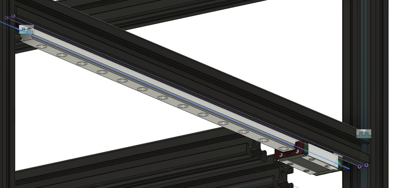
Time spent 1.5h
Day 3 (May 26): Tried to Cad and looked up corexy kinamatics
Today I started to Cad the connectors between the x axis gantry and the y axis linear rails, and completed this only to find out that one of the linear rails was not in the right place. Then I spend way to long only to not figure it out. This problem is really frustrating. I have looked at all the joints and sketches and what not, but couldn't find the error.
I decided to take a break and further my knowledge of corexy kinamatics. I have a basic understanding but want to learn more about it I found this really useful website that explains it.
I don't have any pictures of Cad for the moment, I am still working on the error 😔
Day 3 Part 2: Fixed error
I took a break for a bit to work on another project, after I came back to Fusion I had an idea to delete the sketch and look at the joint which was broken, and then undo it and fix the joint. This didn't work, but I was able to remake the sketch and that fixed it!.
Now I can finally work on connecting the extrusions!
I added an simple part to connect the extrusion to the linear rail, I still need to make the other one and add belt paths.
Pictures of Cad
Time spent 2h
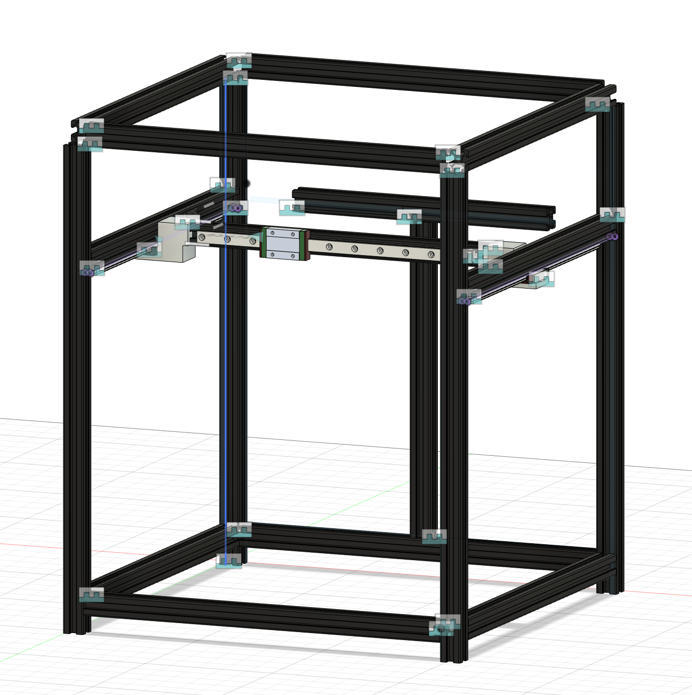
Day 4 (May 27): Cad
Today I started by mirroring the linear rail connector. I then started on the x axis linear rail. I connected the rail, but not the carriage. I will either do that later today or tomorrow.I also need to make the belt path and the idlers and pulleys.
I will upload photos of cad when I finish the x axis linear rail either later today or tomorrow.
Time spent 1.5h
Day 4 Part 2:
While making the gantry frame I encountered an error.
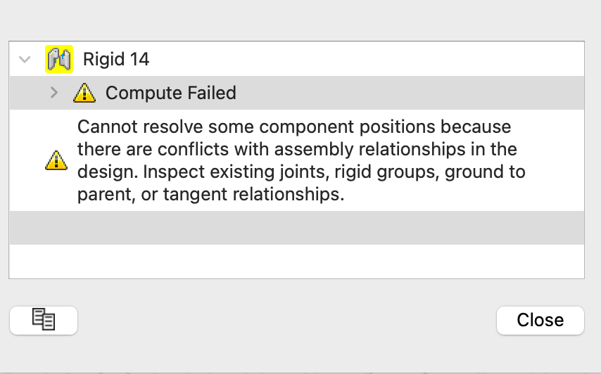
the joint was from one of the linear rails (I had previously connected the other one) to the x axis. T
I eventually fixed this error by removing one of the linear rail slider joints and it worked fine. Then I went in a search for my other linear rail. I have decided to a MGN12H linear rail.
Todo list for later
- Model Belt Path with Pulleys
- Model Z axis
- Model Hotend
- Find remaining parts
Pictures of CAD:
Time spent 1hr
Day 5 (May 29)
I was thinking about the 3d printer and realized I had some design flaws. I accidentally made the y axis 20 mm longer than the x axis which will make the corexy kinamatics extremely hard from the software perspective I also added a extrusion frame on top of the x axis, which is unnecessary and costly. I was also looking at my bom and it didn't line up, with my budget. I will have to work on that today, and fixing the CAD.
I worked on CAD for 40 minutes and almost got to where I left off. It goes so much faster know that I know what I am doing and already have the parts imported.
Pictures of CAD
I still need to change some things, but the design looks way more doable
Now for the BOM. I need to cut some costs because I am somewhere in the 500s. I think my origional goal of 600 mm/s might be a stretch unless I can get some of the other parts locally for cheaper.
For example my hotend, extuder, and mainboard together cost 200 dollars alone which means that I need to get everything else for 150 dollars, which dosen't check out.
Time spent 1hr
Day 5 Part 2
I worked on Cad some more and am at the point where is was at before I changed the model. I modeled a simple version of the linear rail connectors
Pictures of CAD
Time spent 1hr
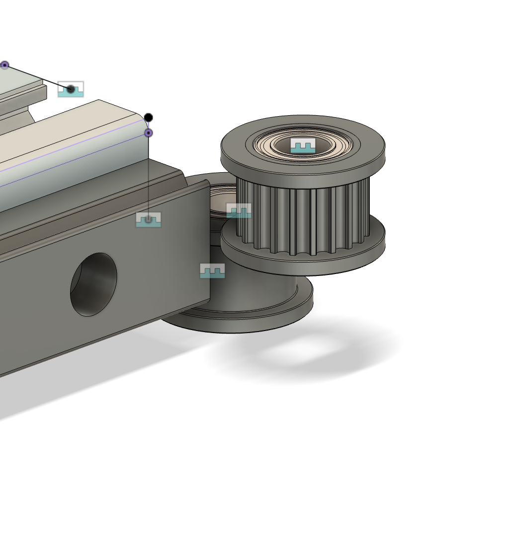
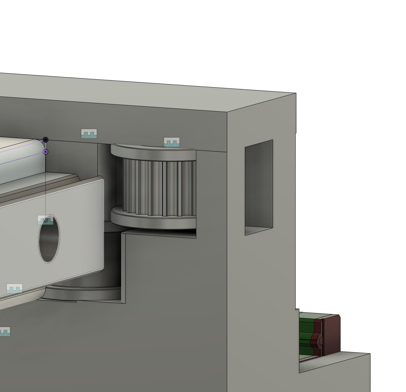
Day 6 (May 30): Started to Cad Belt Path
Today I started to model the belt path where the idlers will go.
Time Spent 0.5h
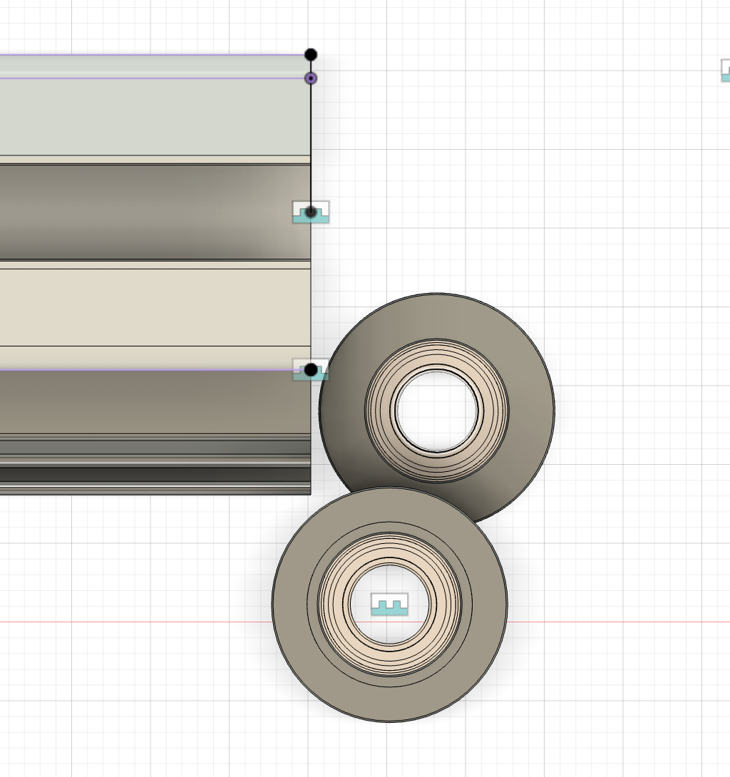
Day 6 Part 2:
I messed around with the position of the idlers and think I found the optimal position. I am designing the part in a different file and will just import into the main design
Pictures of Cad
Time Spent 1h
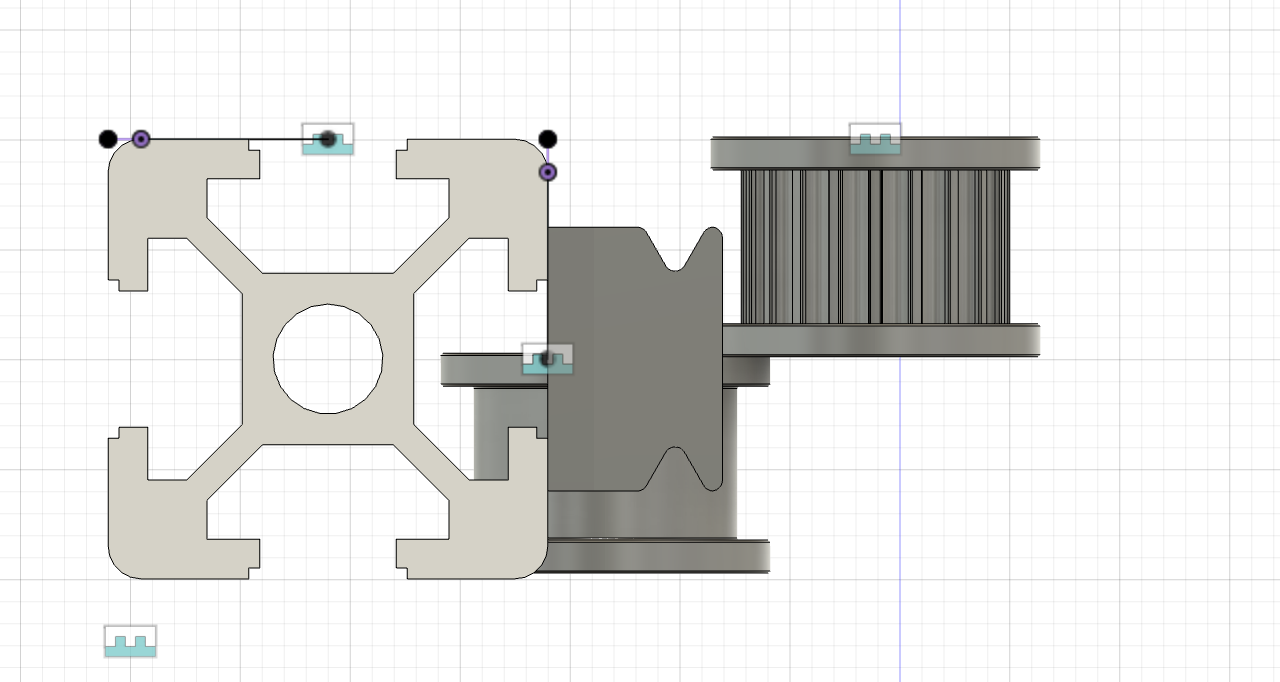
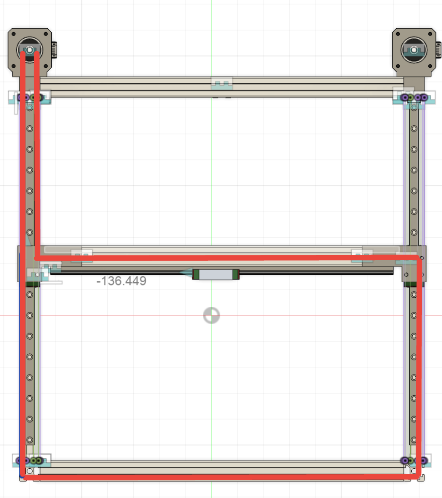
Day 6 Part 3: Finished Cad Mockup of belt path
I finished a belt path mockup for the right side of the x axis. I now need to modify it a little bit and then add it to the main design. I was experimenting with different positions, but I think I found the optimal one. I also need to switch the belts and add it to the left side
Pictures of CAD
I was also looking at the budget. I really need to strip some of the more expensive parts to cheaper alternatives.
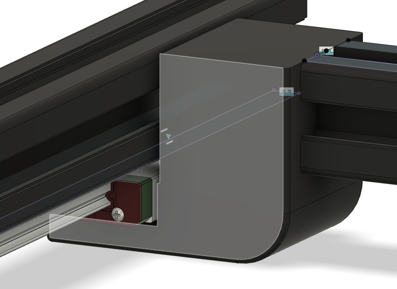
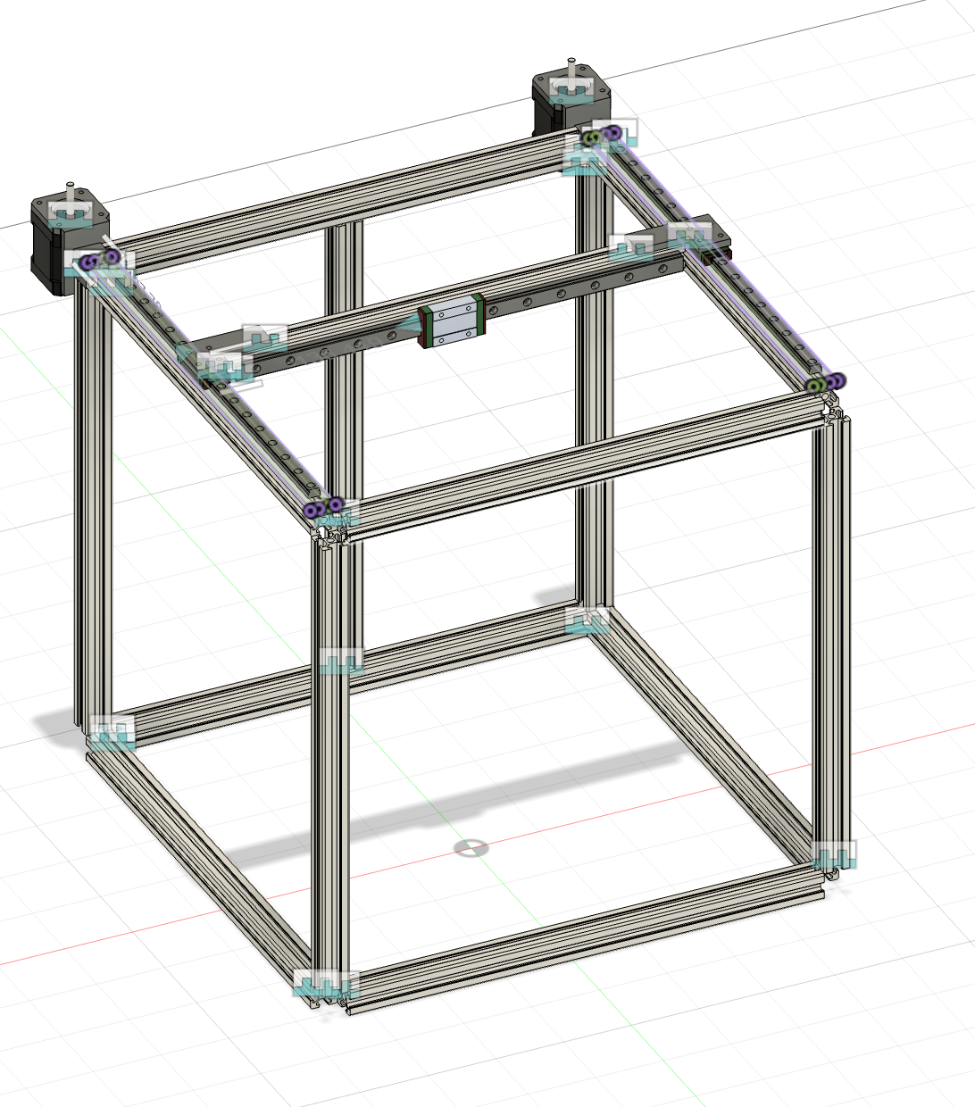
Day 7 (June 7): Modified design continued CAD
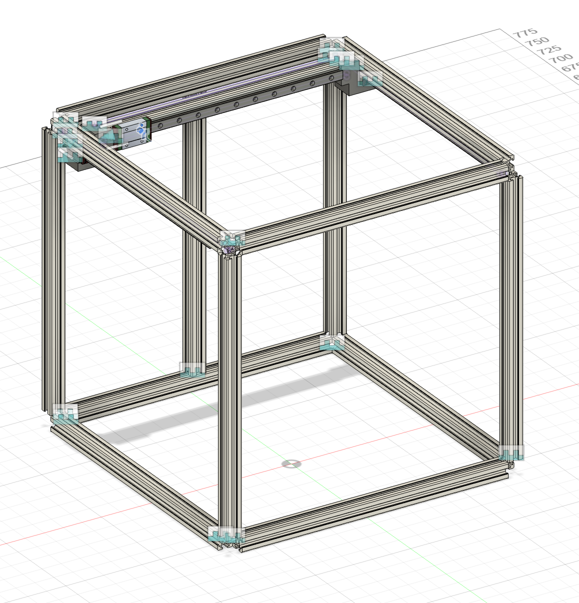
I have realized with the given budget, my expectation is too high. I am going to try to make the printer reasonably fast, but it probably wont hit the 600 mm/s I was hoping for. I have decided to move the linear rails for the y axis to the top of the gantry for simplicity of making the belt path. I have started to model these, but due to limited time I will finish them later.
Pictures of Cad
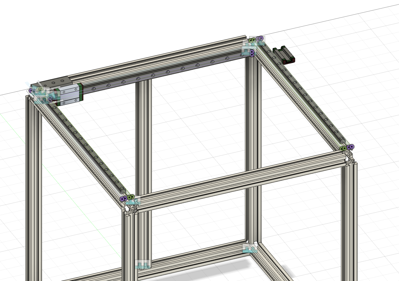
This is the new design I am going to do
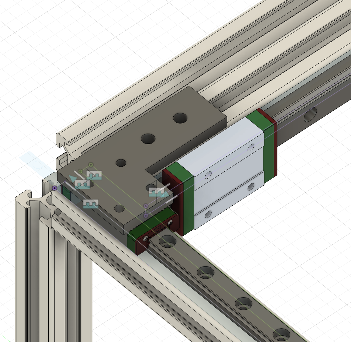
Linear Rail connector so far!
Time Spent 1hr
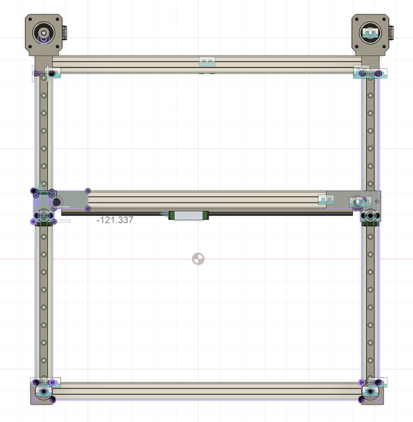
Day 7 Part 2: Added Stepper Motors
I added the CAD files for the stepper motors, and made motor mounts that double as corner cubes. I am going to go with NEMA 17 48mm 56 N. I found these on the voron sourcing guide. Stepper Motor
I also made a mockup of the 2 belt paths for reference
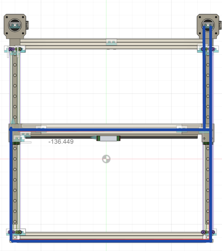
Pictures of CAD
Time Spent 1.5hr
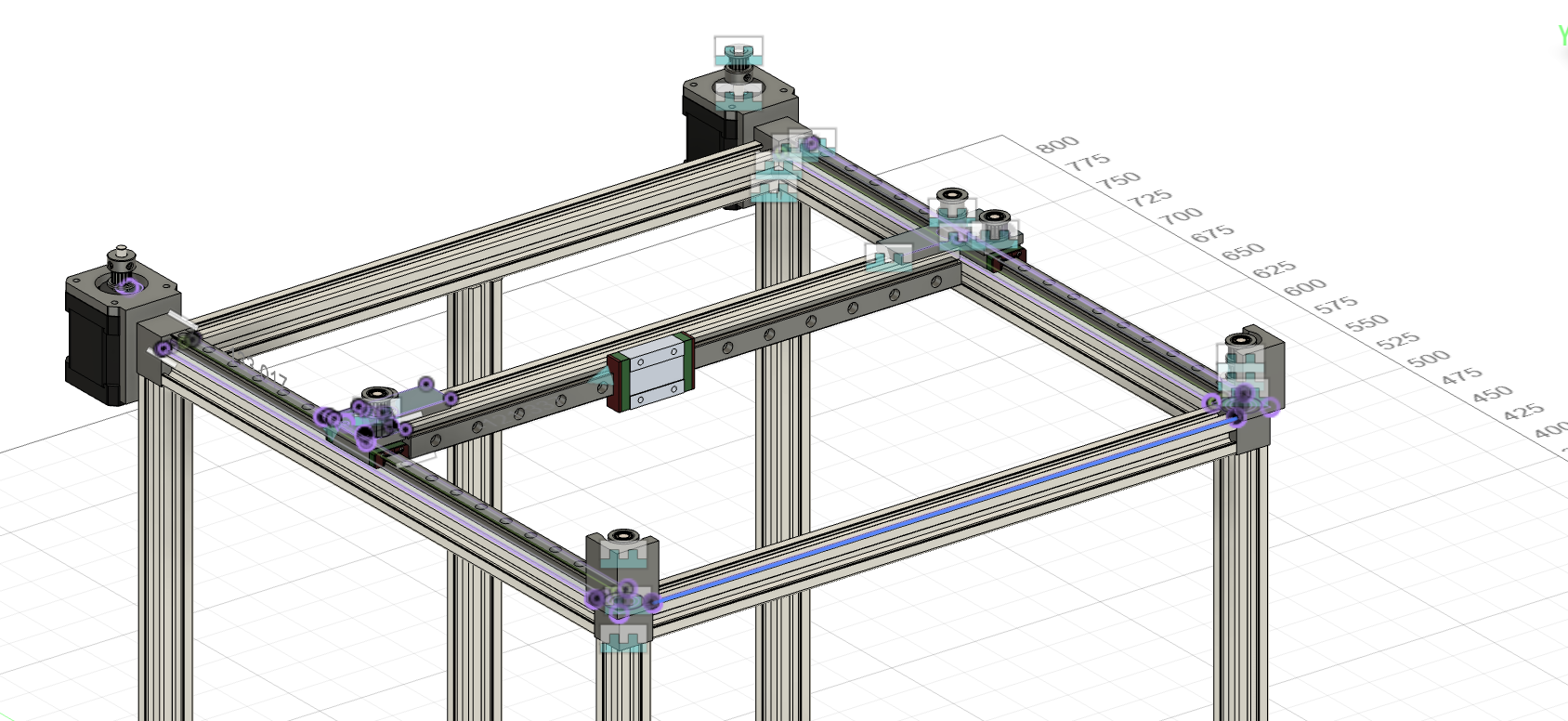
Day 8 (June 8): Cad and BOM
I started today by spending some time finishing the belt path. I am excited because this is one of the parts I felt intimidated by. I decided to route the belts on top of the printer, for simplicity in design. I might redesign some of the components later for ascetics. I am going to work on the hotend and z axis next.
I also started my BOM. I might change some of the vendors later, but this is what I have found and modeled so far.
Pictures of CAD
Time Spent 2.5hr