
Total time spent: 132hrs
July 10th
Last day before Undercity and just spent some time finalising some renders for submission!
July 3rd-9th
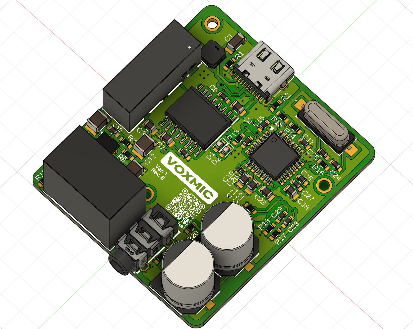
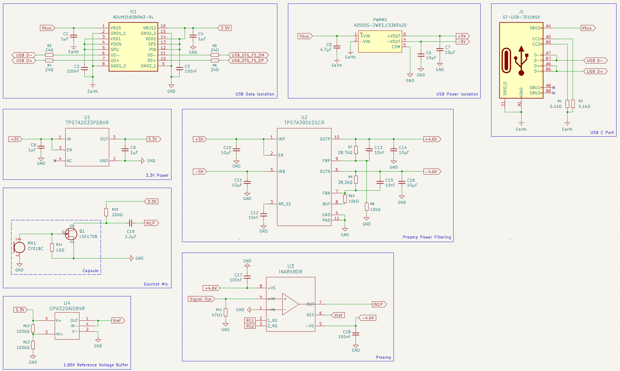
Submitted another 10 point project in the last week! The last few days I've returned to working on the PCB, and finalising component selections. I've also thrown together a quick model of the case and some renders! All the lovely renders are available in the README on Github!
Here's a sneak peak of the PCB~
Time spent: 16hrs
June 27th
HELLO AGAIN THE SCHEMATIC IS FINISHED
Time spent: 3hrs
June 26th
Finished schematic, will do final review tomorrow. Have started working on selecting footprints for SMD components.
Time spent: 5hrs
June 25th
One business week later - I'm partially back! My gimbal has been submitted successfully and the invite to Undercity has been received!! Spent a little time today finishing up the schematic. Realistically I'll work on the PCB tomorrow - its the final week of Term 3 so prepare for some 12hr days over the holidays.
Time spent: 4hrs
June 20th
Significant progress today! However, the project will be put on hold until next Tuesday due to school tests and SAT deadlines. Progress will be journaled next week!
Time spent: 6hrs
June 19th
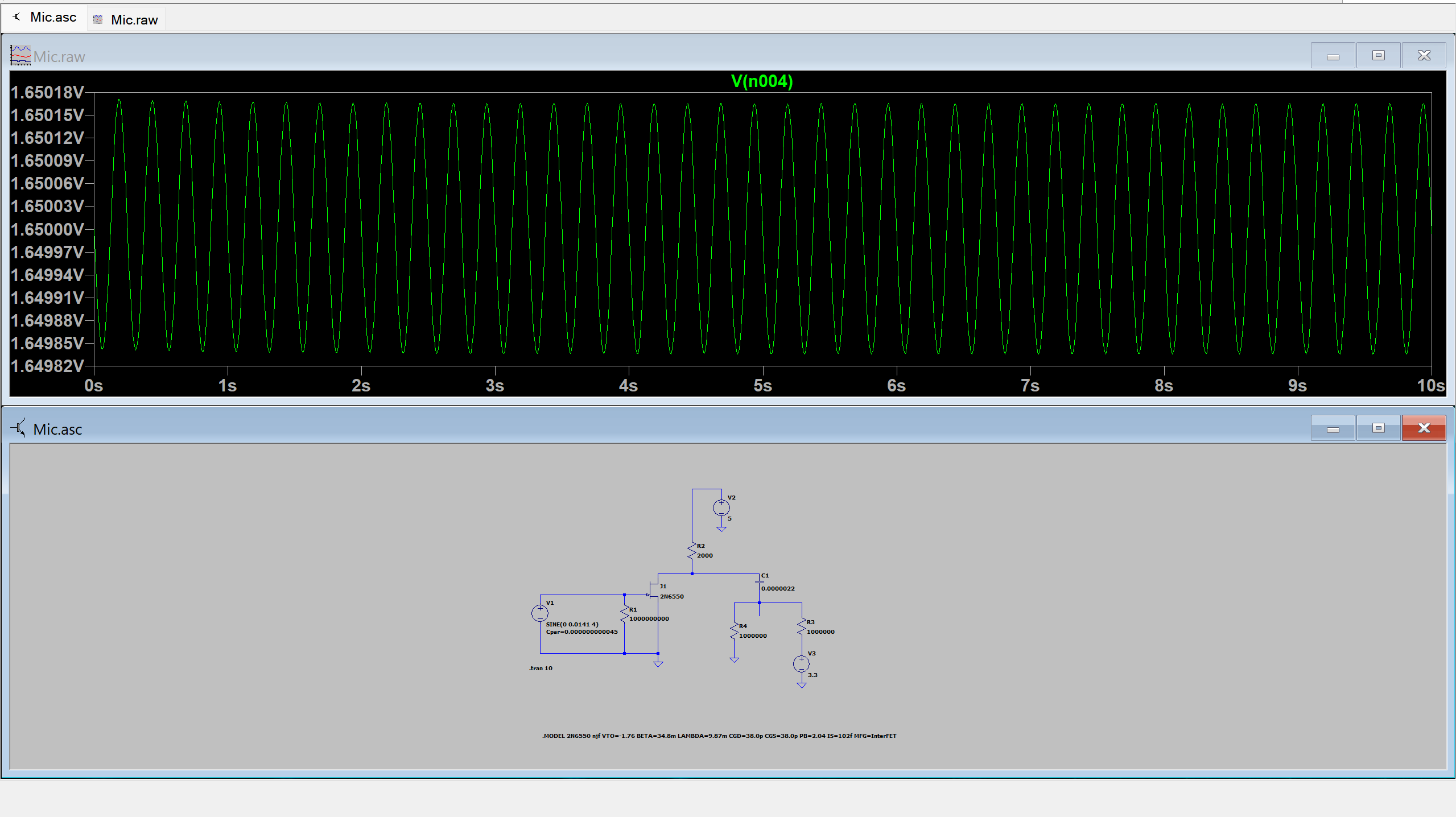
More simulation and math. Mostly images today!!
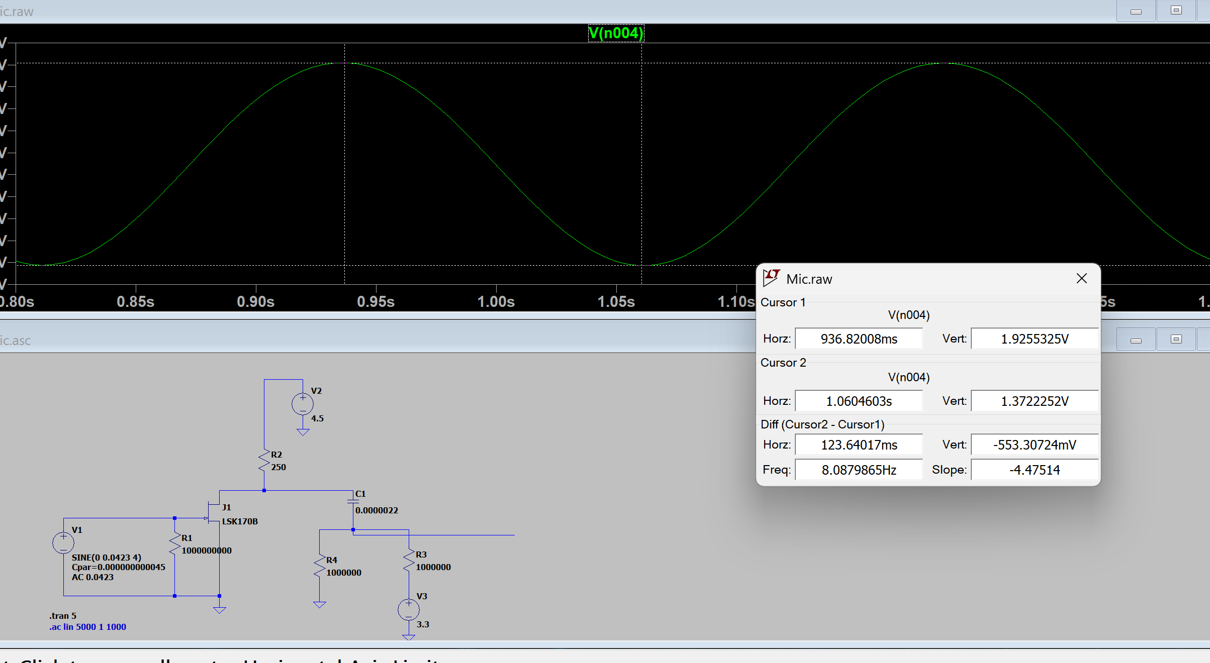 AC Analysis of the JFET output stage
With these results I made:
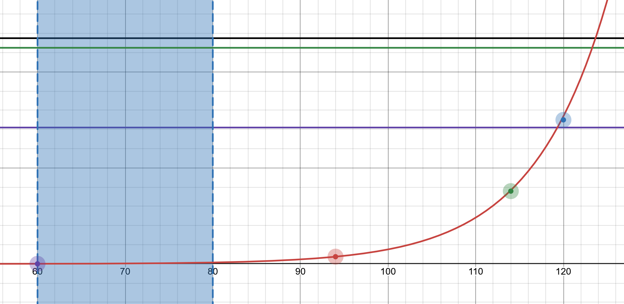 Fig 1. dB to mVPP @Gain=1v/v
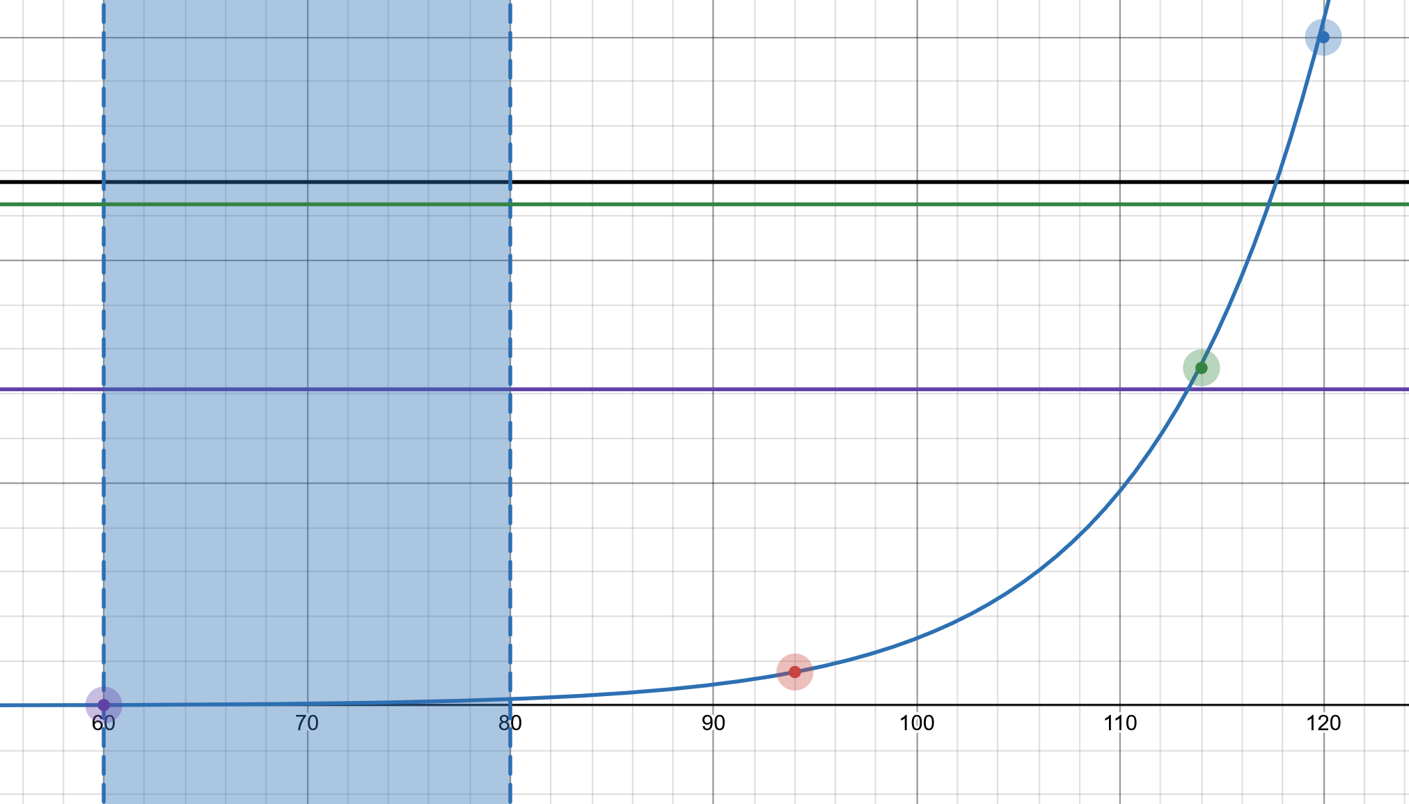 Fig 2. dB to mVPP @Gain=2v/v
The purple line is the recommended max input voltage on the ADC input pins, the black line is the maximum voltage allowed, and the green is the clipping voltage of the op-amp when powered from the 4.5V supply. Honestly, I think going with no gain might actually be okay considering the +20dB amp + the -13/+36dB PGA.
Will look into choosing another N-JFET considering mine is $10... the J305 is looking pretty interesting though!
Time spent: 10hrs
June 18th
Turns out making sure everything will actually work is difficult. Very difficult. Turns out the math behind making sure things don't explode isn't easy. In summary, over the last few days I've been revising each and every component of the microphone to make sure it's functional and well as non-explosive.
Have now moved onto consolidating values for the preamp stage. I've also done some SPICE simulations!
Busy week unfortunately - will try to work on as much as I can.
Time spent: 8hrs
June 17th
Have been sick. Updates returning soon! Note to self: 14.1mV/Pa cap
June 13th
Crazyy amount of work researching and on Rev. 4 - will finish off tomorrow. Also, the progression from Rev. 1 to 4 will be quite interesting to look back at...
Time spent: 10hrs
June 12th
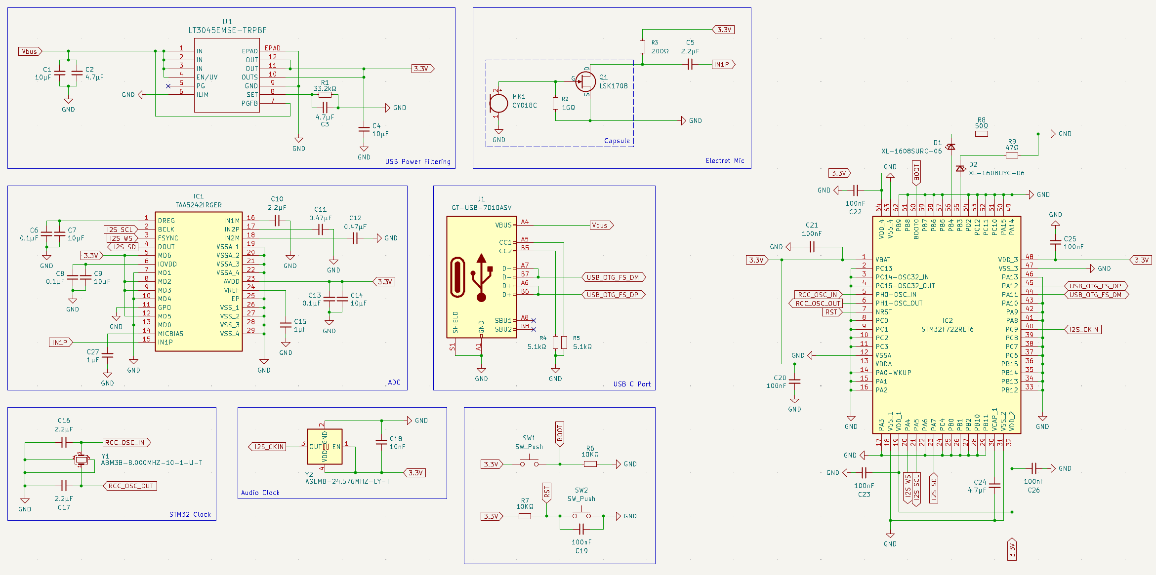
Summary of changes for Rev. 4:
- Add preamp (assumed TAA had PGA like it's I2C version - it doesn't)
- Add USB data and power isolation
- Add DC/DC converter + LDOs for preamp
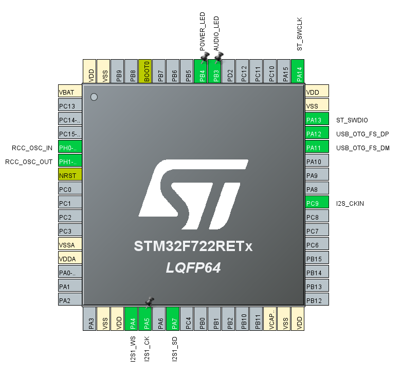
- Fix floating STM32 pins
- Add ST-Link debug pins in case USB doesn't work
Hours and hours of research and reading datasheets behind this move. Also did begin working on some PCB design ideas as well as set up the STM32 CUBE IDE environment. Finishing off today's log with some screenshots.
Time spent: 9hrs
June 10th, 11th
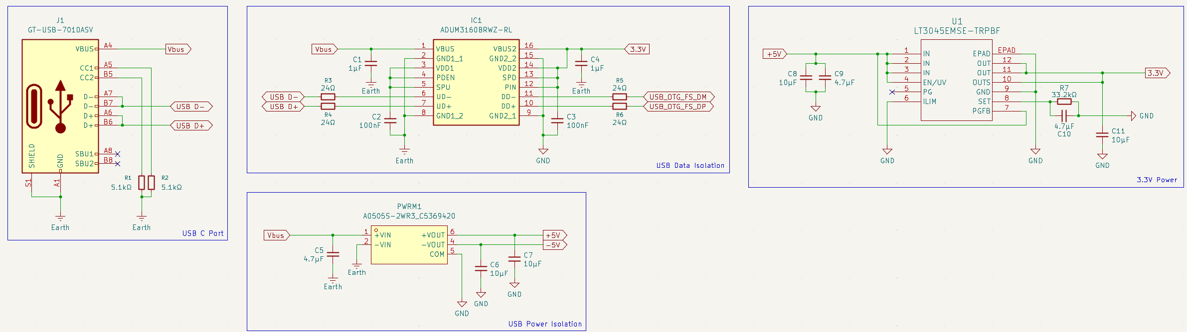
Worked on the schematics for system today. I'm expecting Rev. 3 to be the final version of the schematic.
Thanks to the new STM32 microcontroller and ADC, the power circuity has been dumbed down even more! Since the 5V-ish Vbus only needs to go down to 3.3V, only the LT3045 will be needed to do all the power filtering!
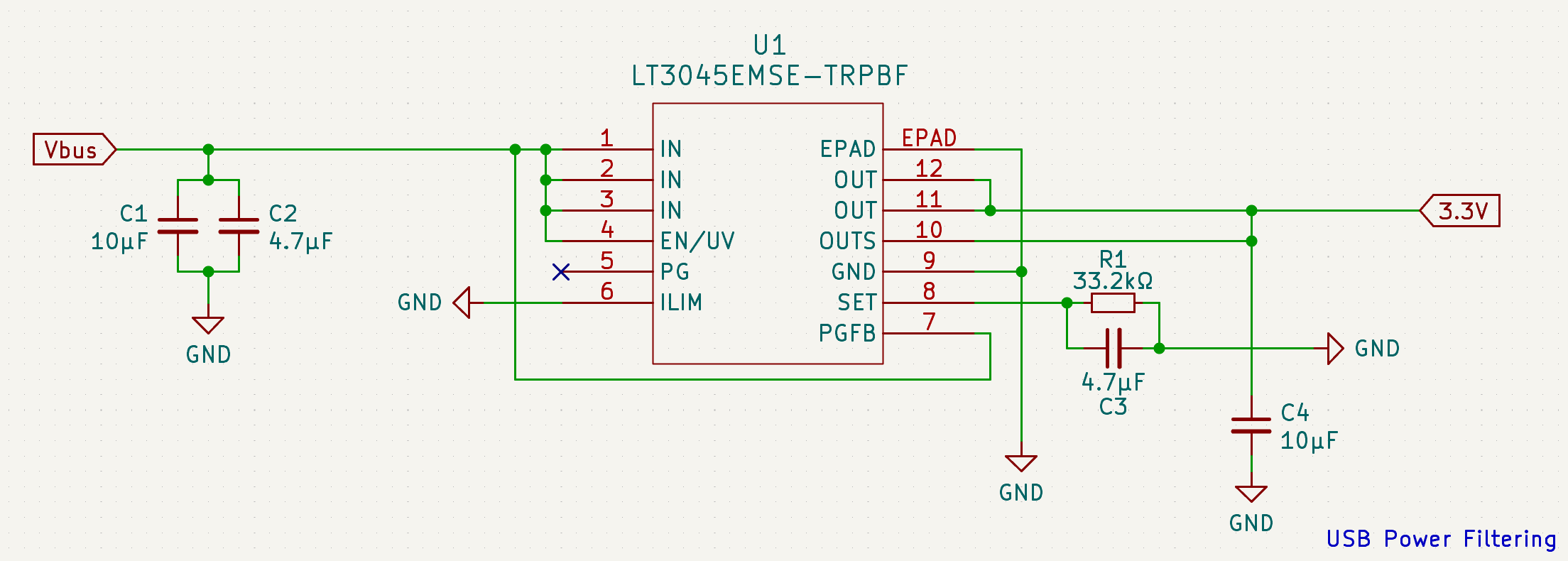
Explaination soon:
Time spent: 14hrs
June 7th, 8th, 9th
Work over the long weekend! Lots of research (AMA) and thinking... thinking... thinking... In conclusion - time for a 3rd revision!
Time spent: 8hrs
June 4th, 5th, 6th
A lot of research looking for USB-chips..., STM32 Audio Class implementations... So much time, so much pain.
IN SUMMARY
- XMOS (the standard higher-end audio chip company) IS EXPENSIVE AND PAINFUL TO USE. Absolute no-go.
- ADC/DAC USB chips from realtech, cmedia, cirrius etc. which are typically used in laptops aren't very easy to get a hold of... and also kinda suck. And outside of these, USB devices are non-existent.
As such, we'll be going the STM32 route! There's middleware for USB Audio as well as I2S communication, so the programming should be... significantly challenging but not impossible.
Time spent: 9hrs
June 2nd, 3rd
Reviewed the schematics over the last two days. A few changes have been made so, I figure this is officially Rev. 2
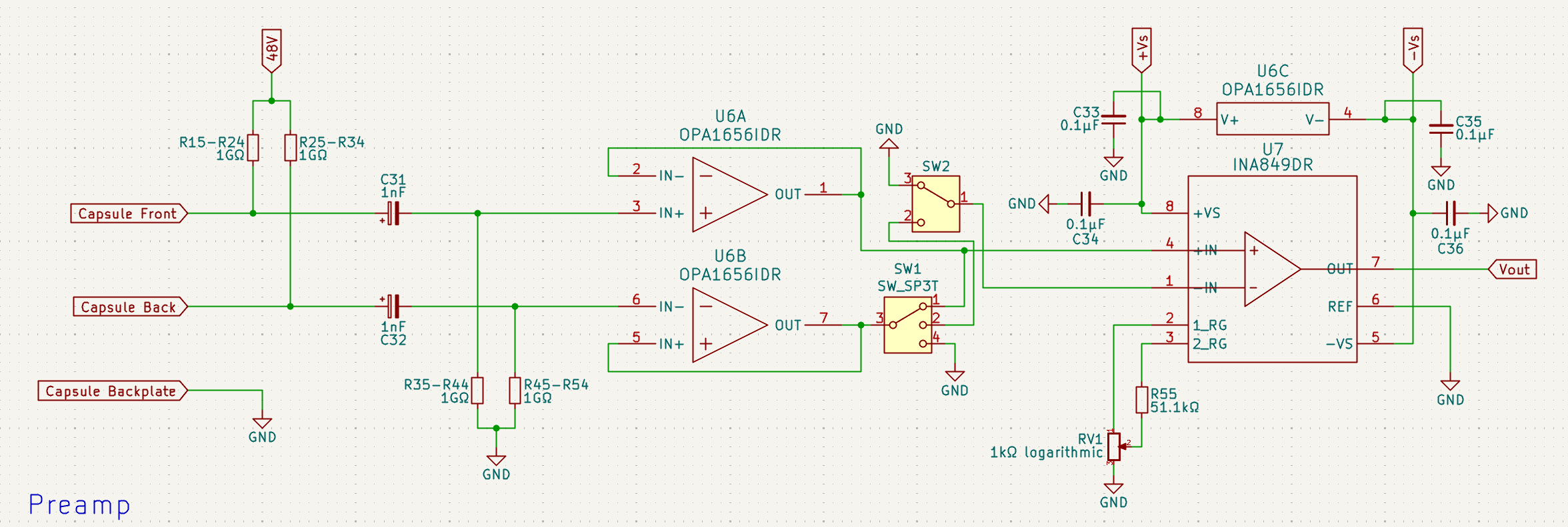
Firstly, the preamp+capsule didn't actually make any sense (TI what are you doing) so I've transitioned to a more traditional preamp. I've also added in variable pickup using a two switches connected to the front and back diaphrams.
Secondly, I caught more than a few miscalculations in the resistor values for some of the power components and fixed them. I've also moved from using two LT4035's to only 1 as after calculating the total power draw, one will be sufficient.
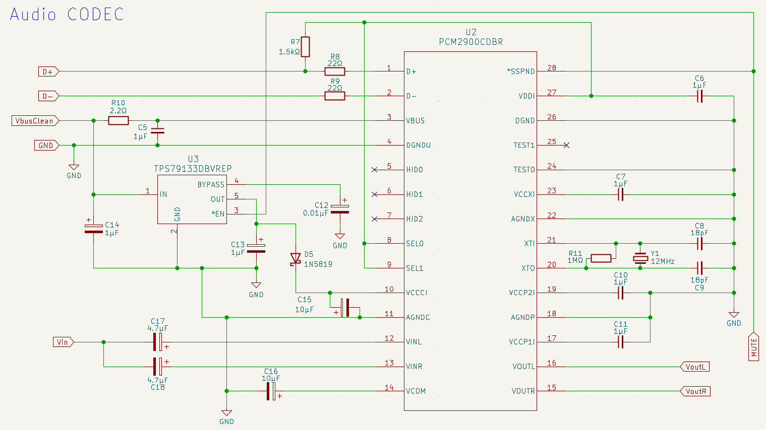
The bigger change, however, is a with the ADC. I've decided to completely remove the PCM2900. Its just not good enough, and it would be a shame to pair it with the analog front-end. The new plan is to use a dedicated ADC, then over I2S or some other protocol with a STM32 or similar, bridge it to USB. Which means the project just got a lot more complicated-
*Time spent: 3hrs
June 1st
Some more work on the mic today! Attempted implementing the PCM2900 to take the line-level signal and output USB. I've also printed (yes printed) the datasheets for all my power components so I can go through and check for errors sometime next week.
Time spent: 1hr
May 28th, 29th, 30th
A bit of work on the schematics over the last few days - been caught up with Hackpad as well as my DLSR Gimbal though. First up was the capsule and preamp - I primarily looked at some example implementations in TI datasheets. Here it is!
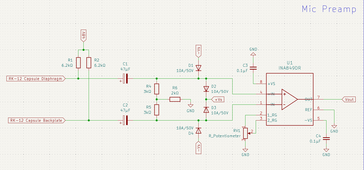
Still not too sure how much of it works... I'll keep it the same as the TI implementation for now until I know how any of it works.
Next up was the power circuitry - it's a bit of a headache but I'll try to explain the basics of each stage.
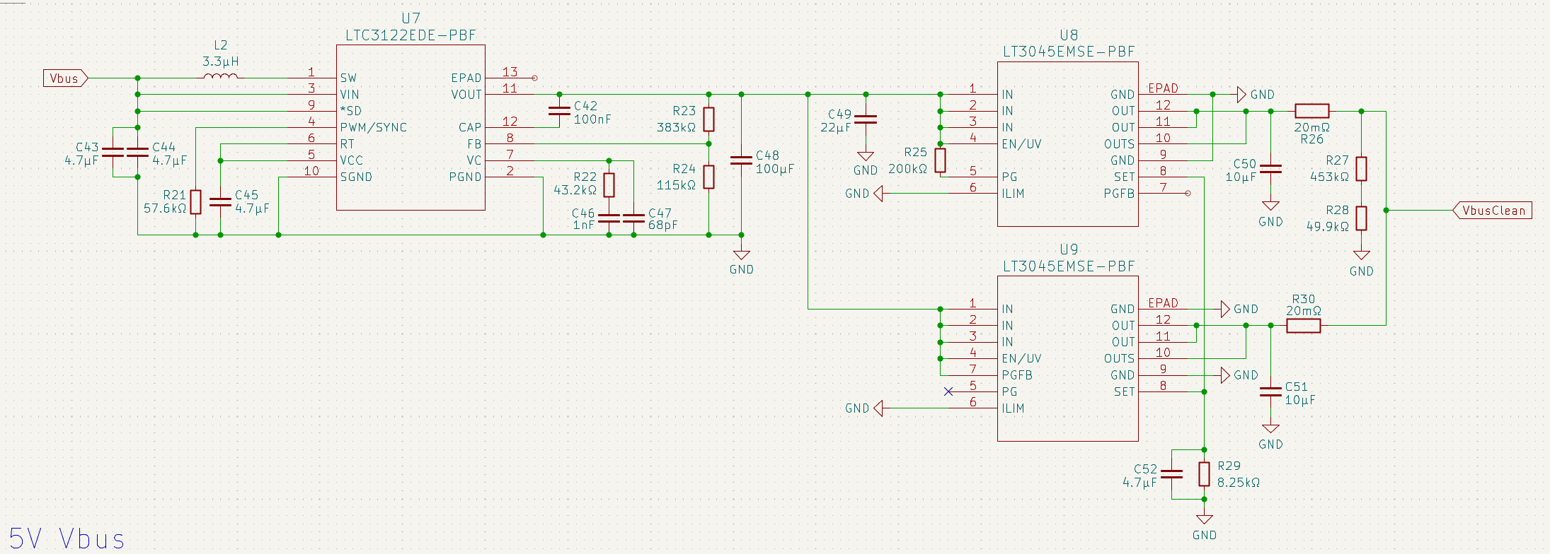 First up here are the components to filter the noisy (and not actually 5V) Vbus from the usb host (laptop). The basic outline for this stage is to take the 4.45V-5.25V, boost it up to slightly over 5V, and the drop it to a nice and clean 5V with a LDO.
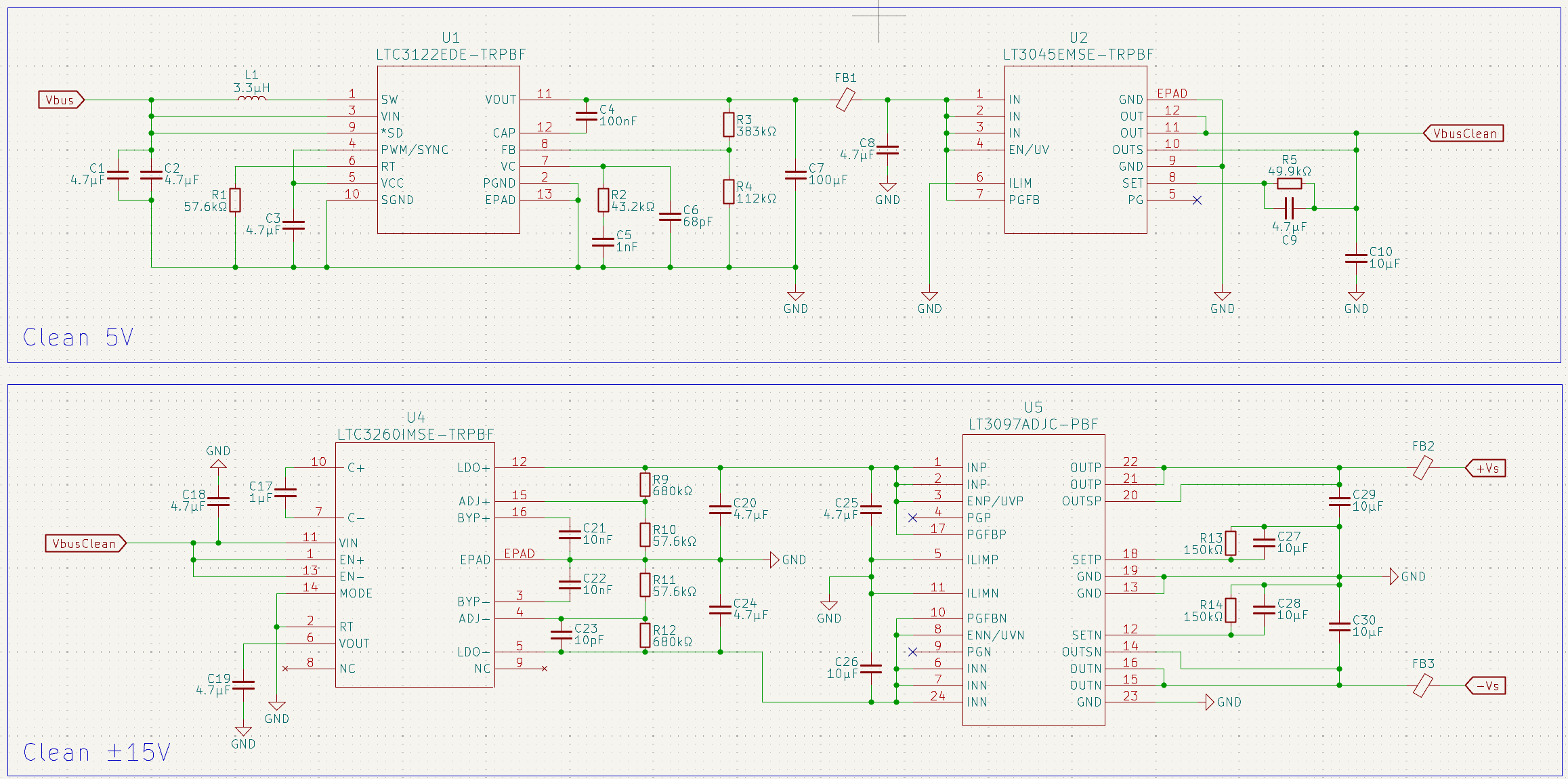
VERY SIMILAR TO THE ONE ABOVE. Takes the clean 5V in, and spits out ±15V (just think of it as 30V but GND is now in the middle) which does through a LDO that supports a pos and neg voltage.
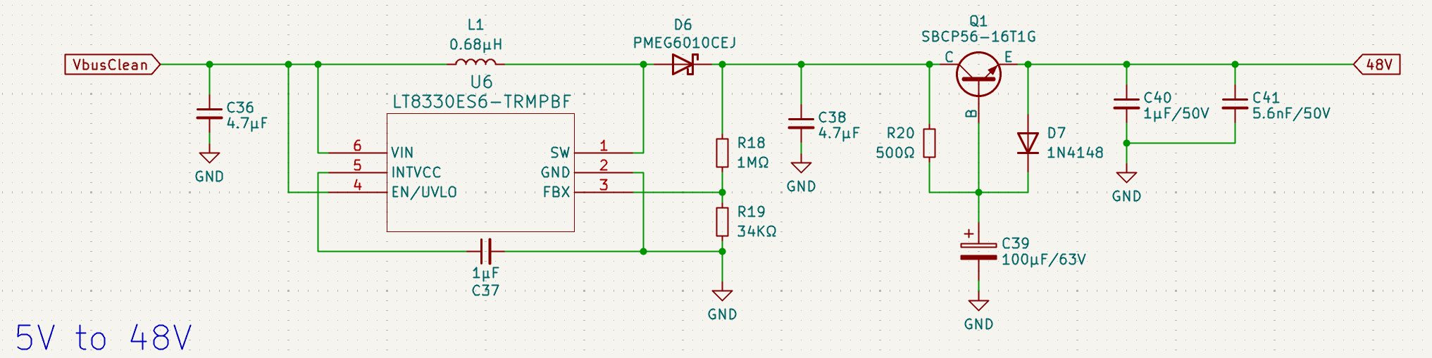 This one's actually from a old THAT Corp. blog post, saves some trouble looking for components (saving a little cost) while also providing me with a schematic I know works!
Overall, progress going pretty well~
Time spent: 8hrs
May 26th, 27th - Final research
Yes I've run out of title ideas...
I'm combining multiple days in the logs because I've just started another project here but we'll make sure to keep going here!
Majority of the last two days has been finding suitable components for the main stages of the mic board. This took so long I feel like I've memorised parts of the TI and AD websites by now. The components I've chosen for now are:
- INA849DR amp
- LTC3265 + LT3097 for 5V to ±15V, then a ±15V LDO
- LTC3122 + LT3045 for Vbus to 5V, then a 5V LDO
- LT8330 for 48V
Interestingly, something I found while scouting the TI website is the PCM2900. It's a single chip that combines an ADC and a USB controller. It's slightly limiting at 16bit/48kHz but let's go with it for now.
Time spent: 8hrs
May 24th, 25th - Let There Be 48V
Finished the initial research phase. so much information on power supply design/components. Powering sensitive analog circuits from a noisy 5V USB line (and oml it's so much worse than I expected) is a major challenge. For PSU components, values such as Power Supply Rejection Ratio (PSRR) etc. are crucial for a clean sound.
In summary, the power will go through a buck/boost converter to get a stable 5V, and then will be followed by a low-dropout (LDO) regulator to clean it up. The LDOs I'm looking at (LTC3045 for example) have a very low noise level to ensure the preamp gets the clean power it needs to perform well.
As the 48V for the bias voltage from 5V requires a significant step-up, I found a great reference design in an old blog post from THAT Corporation that uses an LTC boost controller.
Design begins tomorrow!
Time spent: 10hrs
May 23rd - And Then God Said, Let There Be Sound
Today's research was focused mostlyy on taking the output of the capsule and turning it into a line-level signal through something called a preamp stage. As a true condenser capsule has an incredibly high output impedance (typically in the GOhm range), and has tinyy fuctuations when in use, you need to amplify the signal before processing it digitally.
Most of the day was spent reading application notes from TI, Analog Devices, and THAT Corp (yes, THAT one) and looking into some existing DIY microphone designs, either way I'm pretty sure I'm in for a world of pain. Already thinking of some components for the device.
Time spent: 5hrs
May 22nd - In the Beginning, There Was Nothing
Beginning work on the project today! The main inspiration is the DIY Perks USB Mic, but I want to go a step further and build one for myself while understanding the theory behind a mic. First decision - the capsule. I've settled on a RK-12 style knockoff off AliExpress that looks promising.
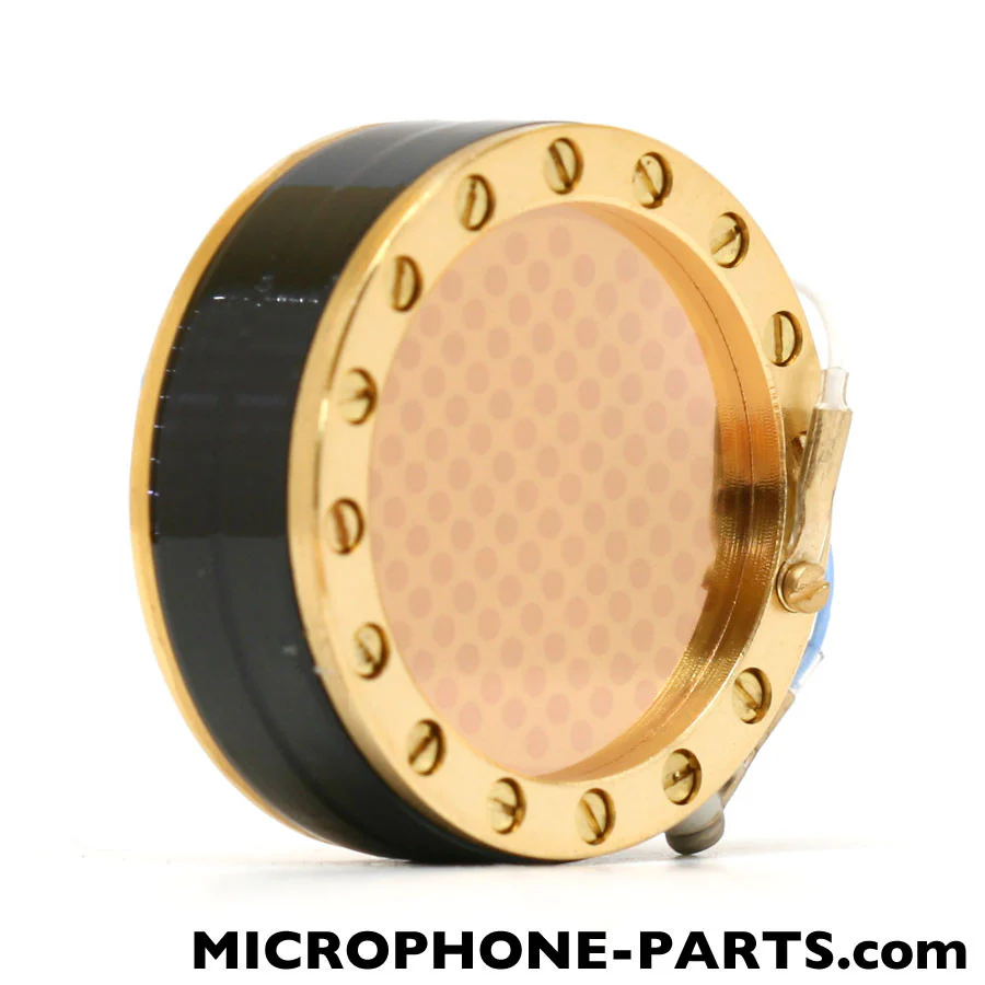
It's dual diaphram (as far as I can tell) with a single blackplate in the middle. This does mean however I will be building proper a high-voltage bias supply and proper preamp.
So what's the difference between my project and your standard DIY Mic? Well, it's going to be USB, while majority of DIY mics are XLR (saves the pain of USB stuff and other amp issues). Anyways, I'm expecting the next few days to be insane amounts of research considering... mic design has quite the learning curve apparently.
Time spent: 4hrs