
Total Time Spent: 43.5 Hours
Stagekit - Journal 1 - 13/06/2025
Alrighty! I am pumped after just submitting my previous Highway project (Lens Board) and am super hyped to get started on this one.
Today I'm literally just going to braindump for this journal, and maybe come up with a proper idea of what I'm doing.
I'll do a summary at the end of this journal with the general idea + diagrams, so skip to there if you don't want to hear this absolute atrocity of a writing extravaganza.
Brainstorm
Mini stage lighting kitset kinda thing it'll have a bunch of lights, trusses, and maybe a little fog machine run by a rpi zero 2 w.
Truss should be either buyable (aliexpress) or printable, so i'll need a solution for that
maybe straight segments buyable in one size and then just make brackets and stuff for everything else that are 3d printable
don't have a resin printer and that will probably be necessary for this, so will need to fab enough stuff through jlc3dp
actual spec-
Spi or i2c - pros and cons
nvm, spi has limitations with num devices (like max 16 slaves probs + takes a pin per slave i think) :skull: absolutely not i2c it is
Do they just send channel data like dmx, or do I try and establish more of a actual data connection between like rp2040's or something
Would prefer something not as expensive as rp2040 ~1 usd per chip might be much? would probs be like 5nz per fixture hmmm 16 * 5 = 80 Would prefer closer to \$3 per fixture we'll see
Maybe those little microcontrollers with like 8 pins
but also will need a decent number of pins for e.g moving lights
it would be good to be able to use multiple chips
but id really want to write usb from scratch
mayb i2c makes it easy? research later
Size is important, how big should stuff be? I want a consistent scale, so maybe doing an actual to scale value would be good
Megapointe is 64 cm tall, so maybe 1:10, so 6.4 cm? how big would a stage be at that height?
mayfair proscenium is 10.6m wide, 4.5 high, and 6m deep at 1:10 that would be 106x45x60cm
bit big slimpar size is 253 x 98 x 290 mm would be 25x9.8x29
might be pushing feasibility for pcb + case + leds
dunno seems possible?????? pcb is 1.6, light might be 5mm +- 2mm, that leaves between 1.2 and 3.2 mm wall / other size doable
wouldn't want to go smaller, so min 1:10 scale.
cannot find any truss thingys on aliexpress, keep looking later but maybe all 3dp
makes it easier tbh
if its 1:10 scale, how thick are mounting things on eurotruss?
Eurotruss ST is 30mm rad would be 3mm so 6mm diam could be fine? - check resin print tolerances
its fine
inter big one things might need to be thicker tho, but thats fine
Clamps?
Maybe just have hooks on the lights, doesn't really need to be detachable or anything, they're mostly going to be hung the same way
going to sleep now, will cont. morgens
Es ist morgens jetzt
Ok, continueing
clips can just be 3d printed attached to the lights probs, maybe rotateable but i can't imagine it really mattering unless you want to put it in some wacky orientation
I want to have a moving light, but motors will be hard will see, maybe those mini servo things or stepper + encoder
Anyway, list of what I want, to scale obv
- 15m straight truss
- 5m straight truss
- 2.5m straight truss
- 1m straight truss
- Truss corner 90
- truss corner 45
- truss junction 8 way
- truss junction 4 way
- truss t junction
- truss junction 3 way
- rgbw par (sim to slimpar pro h usb?)
- rgbw tube (single - 8 pixel, not sure how many)
- moving head (megapointe size, bc smaller might be unrealistic)
- smoke machine (ultrasonic vaporizer maybe? don't know how water based is for electronics lol - pause, i can just tear down a vape :skull:)
Alright, that seems like a reasonable scope.
In terms of control, I would definitely like art net, maybe dmx input, but idk how that would work on pi.
Each light will need data + power.
Want super small cables, too thick and they'll look ugly as hell. Could make my own with enamel copper wire + heatshrink, but would need connectors still.
Connectors probs molex, but maybe..
hold up could use 4 pole headphone cables? maybe too much depth required
probs JST-SH or picoblade
The Idea (refined)
The main concept for this project is a mini kitset stage, complete with working lights and a fogger, for use as a decorative piece or for lighting previs.
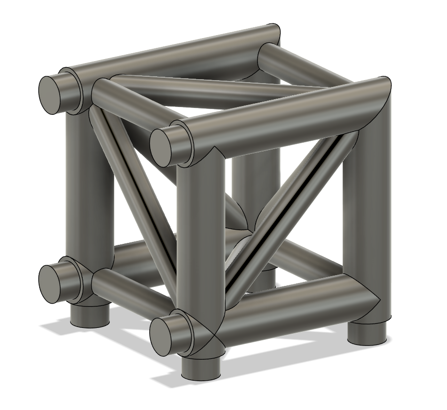
The system uses a mostly consistent 1:10 scale, as shown in the image below.

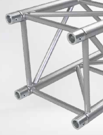
The object shown is the standard Eurotruss size, which is normally 510x510mm, but in my scale model, is 51x51mm.
This size was chosen due to its resulting sizes of the beams, which are in the scale model, a diamter of 6mm, which is within the capabilities of a resin 3d printer, which is the intended fabrication method for the set.
The Stagekit system will use an array of truss shapes, which can all be connected together to form a stage, as well as several varieties of lights which can be clipped onto the trusses and powered to be controlled either automatically or from art net, driven by a Raspberry Pi Zero 2 W or similar.
Each light will communicate over I2C delivered through molex cables, and have either an STM32C011F6 or ATTiny804 chip which will control and potentially drive the LED's, motors, or other hardware.
In its current form, Stagekit will consist of the following elements: - Variety of truss elements - Various set dressing elements - RGBW LED Par - RGBW LED Tube - RGBW LED Moving Head - Micro Haze / Fog Machine - Control Module
Start of design
I've decided to begin by modelling the basic truss, so time to fusion 360 for a few hours.
I'm actually going to go with slightly different than the official eurotruss spec, going with a 10mm main tube diameter rather than 5mm, just to add additional support, while keeping the overall 51x51mm profile
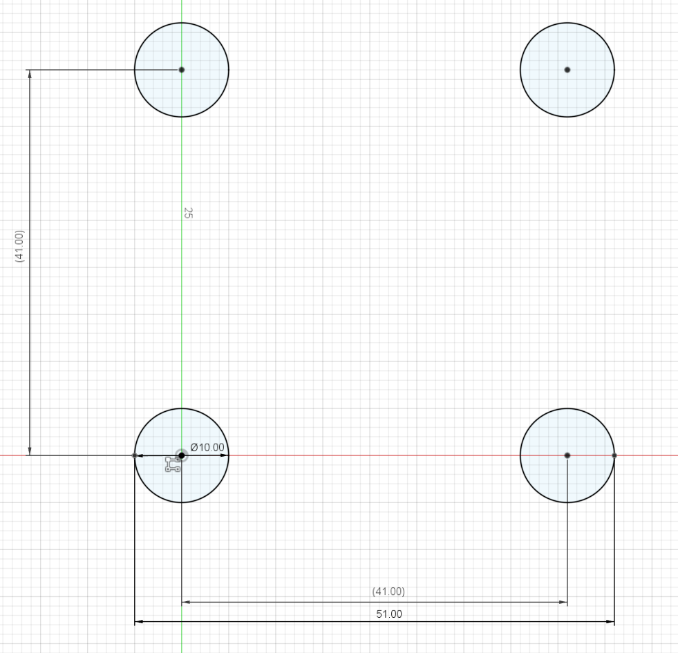
Likewise, for the braces, I am going to go with a 6mm diameter rather than 3mm, so as to make it more printable and also look a bit better.
Each truss has a 7.5mm 'clear zone' at each end, for connecting brackets later, similar to the official eurotruss, but in my case, there are probably going to be 3d printed sleeves rather than bolts.
Adding in the support beams,
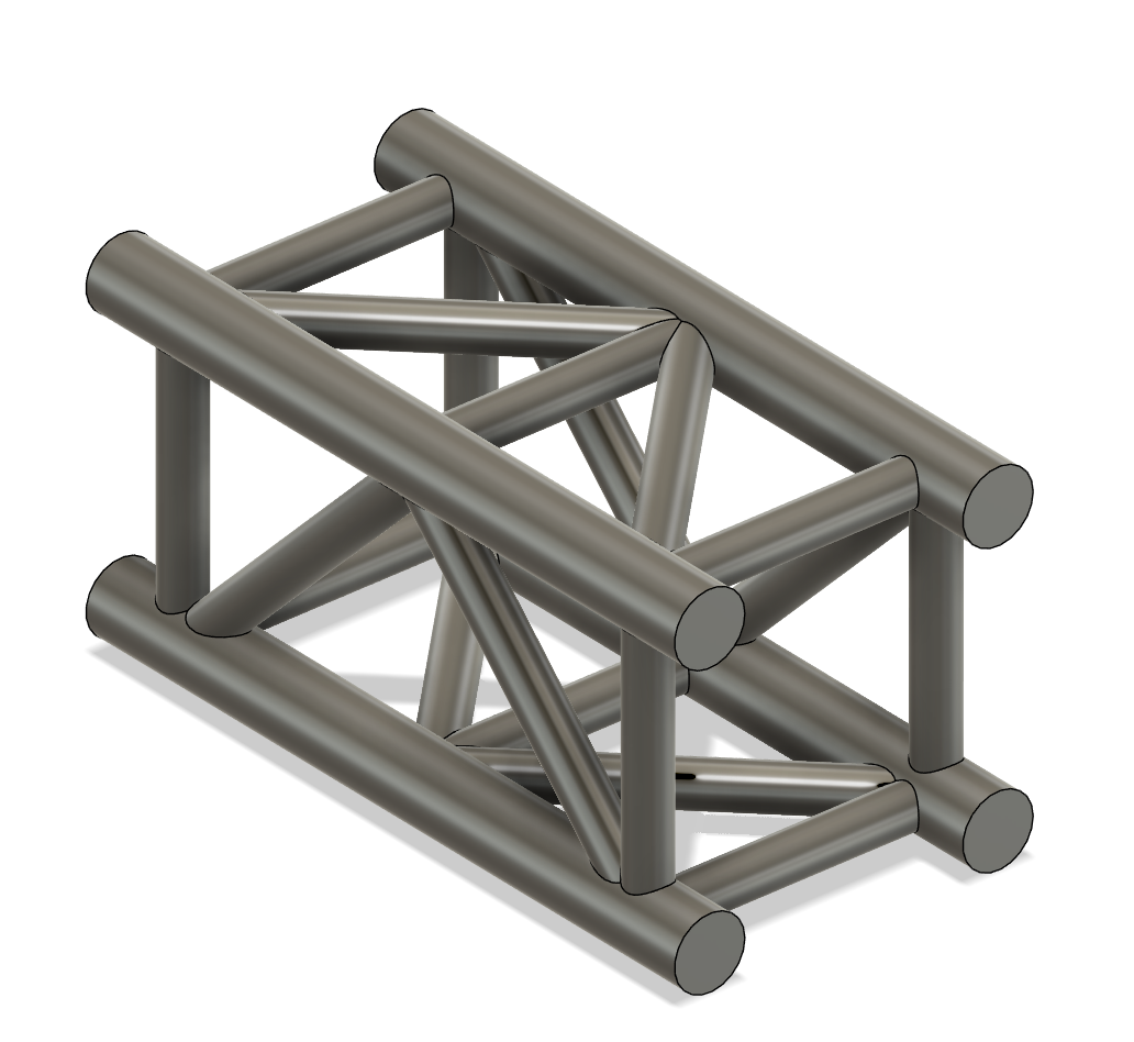
And the 1m truss section is mostly done :) I'm also going to add a slight chamfer on all of the corners, just to make it look a bit prettier and add some more structural support when printing.
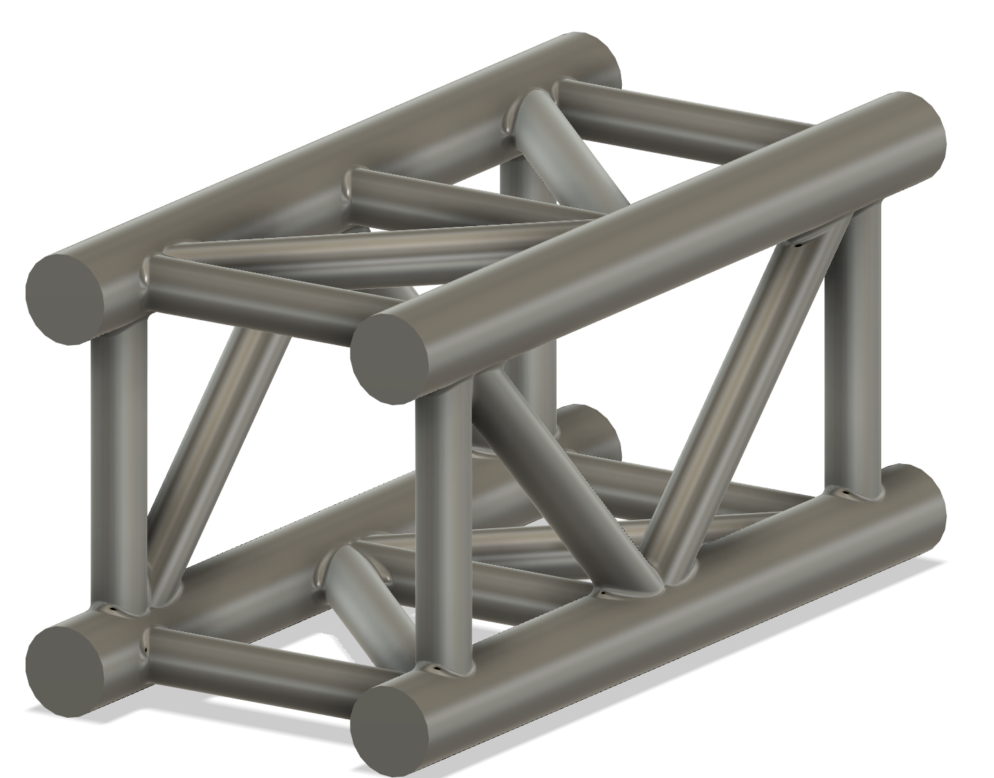
And thats the first truss piece complete. This is the 1m (10cm) straight piece, and I have a couple more variants of this I'll make tonight.
*Note*
I quoted this on jlcpcb using sls resin (the cheapest possible option)
and its currently sitting at $3.91 a piece, which is pricy, so I might
have to compromise on scale and go to around 1:20, which should roughly
halve the price, but might introduce issues with keeping a consistent
scale between lights and the truss, as moving heads will be difficult
when they're only 32mm tall :(
Alright quick sidetrack
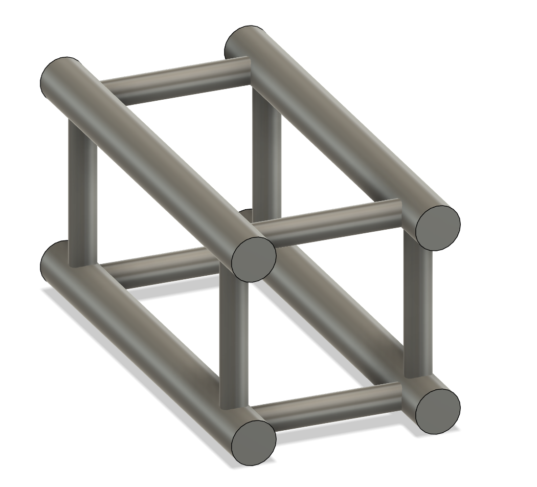
What if I used carbon fiber rods (or similar) for the main truss chords instead?
I can get 500mm of OD:9mm ID:6mm Aluminum tubing for \$1.98 on aliexpress.
100mm straight truss would cost \$1.58 for the four main chords.
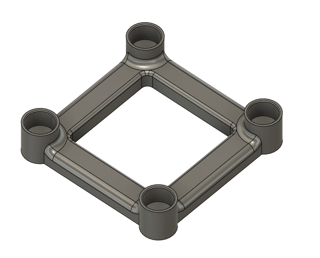
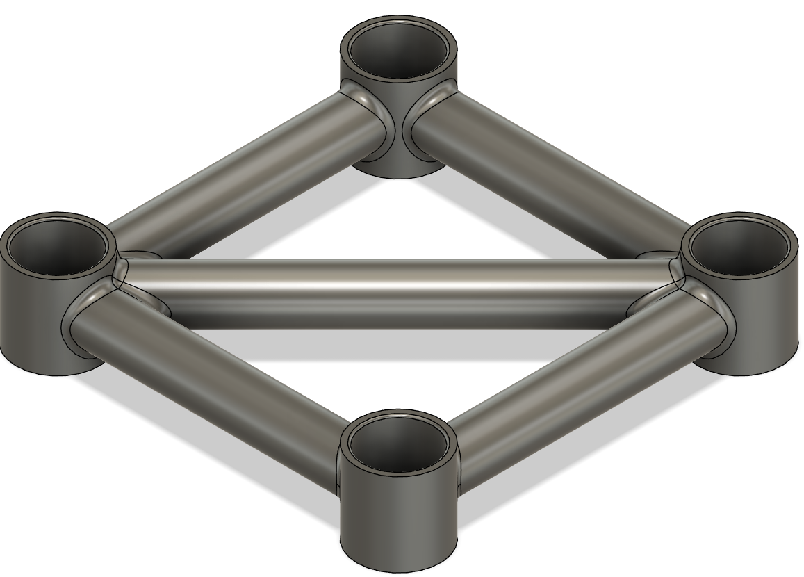
I quickly designed this bracket, 3 of which would be needed per section of truss.
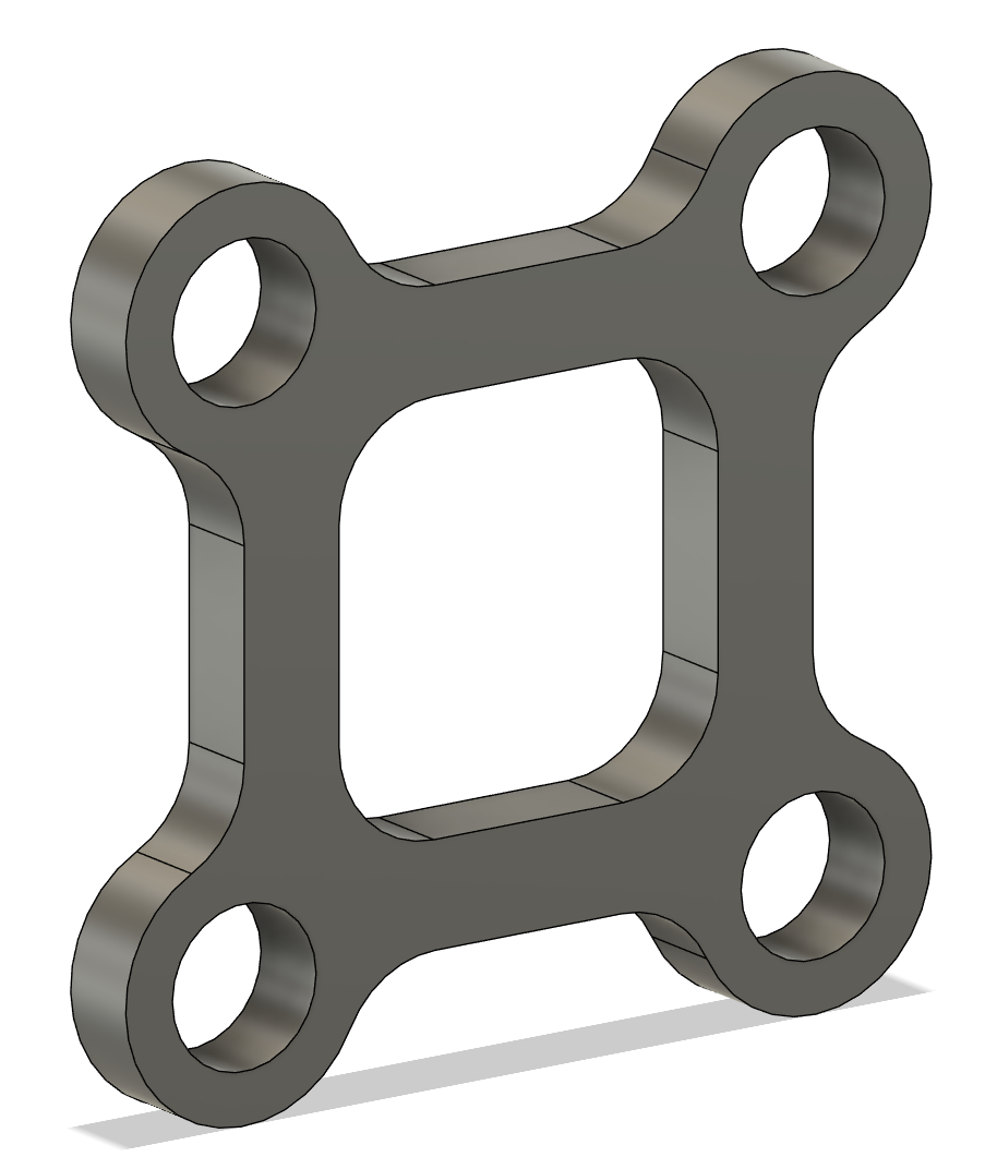
These would cost \$0.41 each, so \$1.23 per section of truss.
This results in a final cost of \$2.81 for a 100mm section, which is significant improvement, however, I'm not sold on the look of these trusses, as they're missing the crossbeams which I so dearly love :(
Sidetrack number 2
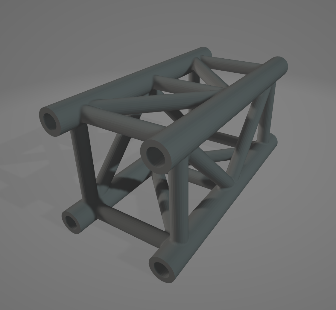
What if I just hollow out the truss segments, 10mm is more than thick enough to print, I could probably make it a tube with an OD of 10mm, and ID:5-7.5mm.
Alright, I've made two versions of this to test and the results are promising.
Version 1. - OD: 10mm - ID: 6mm
- Price: \$3.04
Version 2. - OD: 10mm - ID: 7.5mm - Price: \$2.54
I'm not massively comfortable with version two due to the thickness of the walls, so that might be a no go.
Sidetrack number 3
What about me just fdm printing myself at home? I'm really bad at printing multiple things, and my bed is super rough to print on (adhesion is so bad I need tape to get it to stick at all) but it will likely be way cheaper than sls or ordering online (jlc3dp charges $5 for the hollowed version fdm).
Chucking it into cura, it's approximately 50g of filament used, with a 9 hour print time on my printer.
Looking at Jaycar, 1kg of ABS filament costs \$21.57 (which is admittedly pricy but it also has no shipping costs, so this could be roughly average? I'll check aliexpress later). This would mean a cost of approx \$1 per 100mm segment, but power costs are also real, and this would be around 150w per hour, or for a 7.5 hour print, 1.13kW. At the rates where I live, this is around an extra $0.20 per segment.
In total, \$1.20 per segment
*Note*
My model is currently not the most efficient, when standing vertical, most
of the cross beams don't need support because they are at 45 degree angles,
but there are two cross beams that are horizontal, and thus need supports
I think if I took these out (they're not important for structural integrity,
i'm not needing to actually match the eurotruss spec) i could probably save
around 5g and an hour or so of print time.
Wrap up
Overall, the most efficient manufacturing method is looking to be fdm printing myself :(
\$1.20 per 100mm segment I think is a reasonable cost, and I'll probably have around 10-15 in the final kit, as these will likely be the most used parts.
I think todays been a big success, I've not only got the full idea down, but designed one of the essential pieces, figured out some manufacturing stuff and also gotten a reasonable grasp on what to do next.
Looking forward to continueing tomorrow :heart:
Time Spent: 6 Hours
Stagekit - Journal 2 - 15/06/2025
Today was not a fun day :(
I spent around 6 hours tuning my 3d printer, trying to get even somewhat decent bed adhesion without requiring masking tape.
Unfortunately, in this I failed, I eventually gave up and went back to tape, but I did manage to get the printer going 3ish times faster, which is a major bonus.
I managed to run it at around 140mm/s compared to the normal 50-60mm/s for the Ender 3 v2, which isn't actually bad.
I also did some general maintanence: cleaning, adjusting belt tension, adjusting eccentric nuts, cleaning the bed; I even started to get klipper set up with one of my rpis from high seas :)
Overall, not amazing, but not terrible either. This was absolutely necessary given the amount of printing I'm going to be doing, every hour counts.
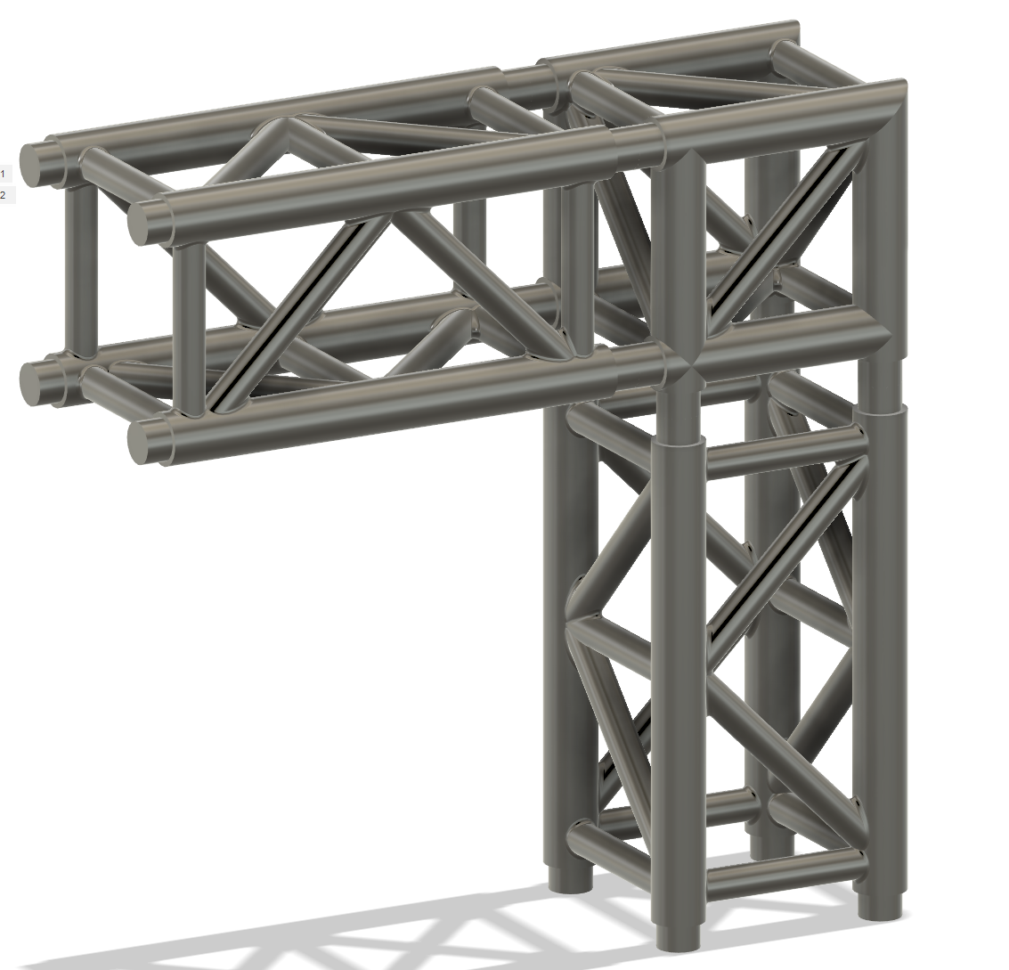
Afterwards, I worked on designing the next truss piece, a basic corner. This was hell. I got the basic design down pretty quickly, but soon realized that my current idea of just having sleeves that connected between the trusses wasn't going to work. The corner would have to be larger than 51x51mm, making an unevenly offset system.
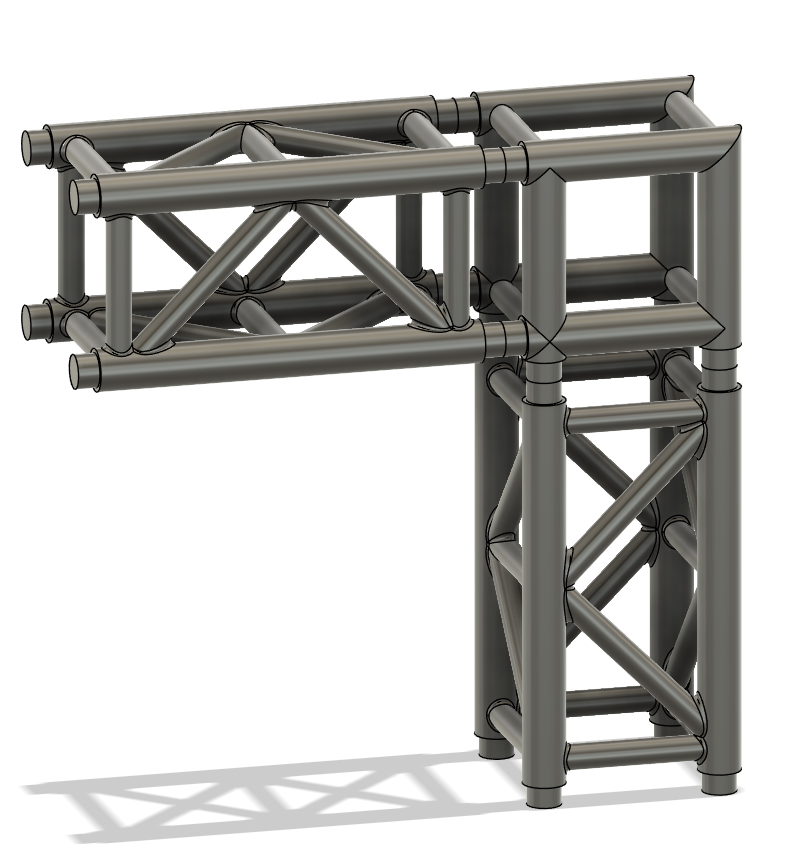
At the moment, I've just gone with this, but I may be able to fix this later, if not, I can just make some special adaptor segments to bridge gaps.
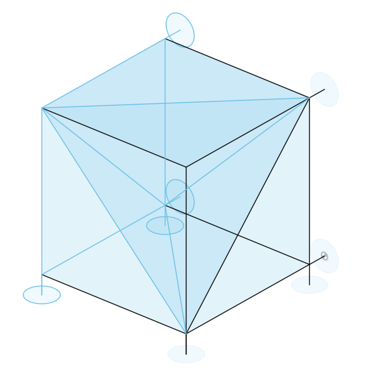
Interesting thing: the braces on the corner form a tetrahedron:
Anyways, thats me for tonight, I need sleep :sob:
Time Spent: 2.5 Hours
Stagekit - Journal 3 - 16/06/2025
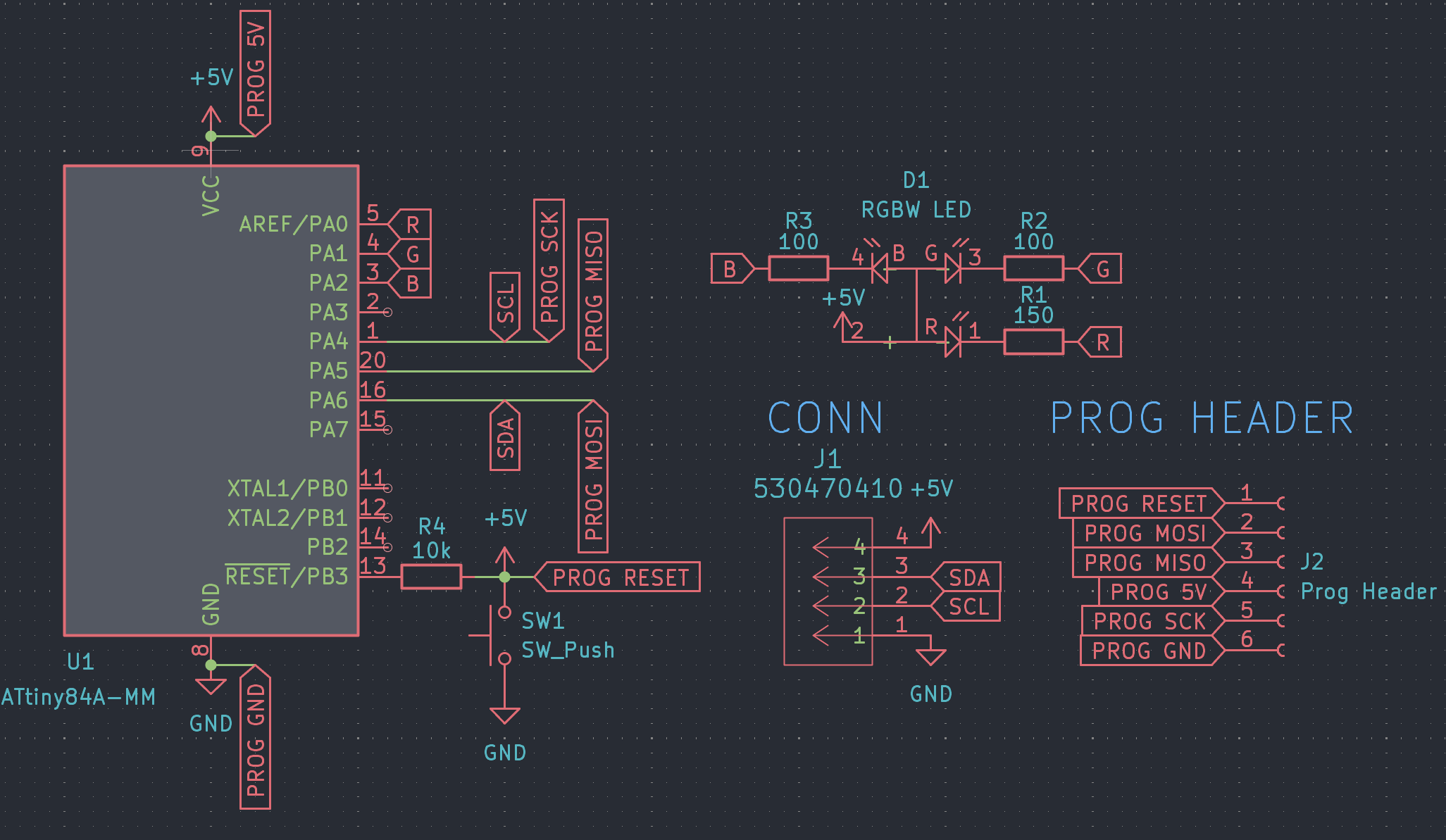
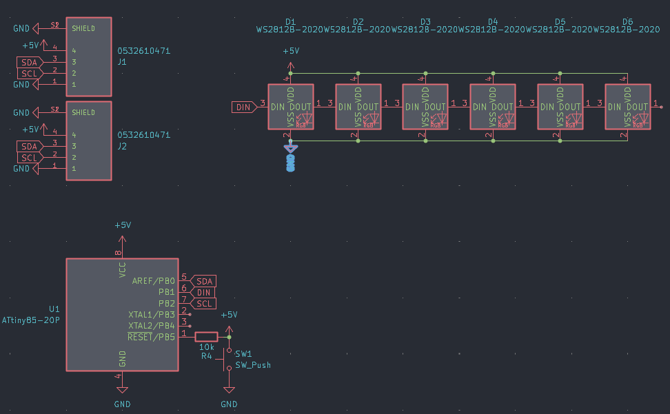
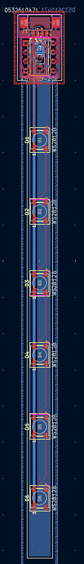
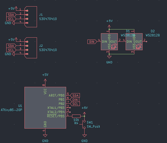
First things first, I made the schematic for the RGB Par (only rgb now, because I can't find any rgbw on jlcpcb for cheap).
This wasn't too bad, but it took a while to settle on a specific MCU, I was torn between the ATTiny804 or the ATTiny84, but eventually went with the ATTiny84a, as this is the mcu for which the I2C slave library was originally tested on, so it has a lot more examples and will overall cause me a lot less headaches.
I was originally really concerned when parts hunting, because the actual chip costs more than an rp2040, ($1.74 vs ~$1), but I quickly remembered that this actually includes an internal clock and flash memory, so is overall cheaper.
Once the MCU was sorted, I went onto the programming, which is not as easy as for the rp2040. Normally, on the rp2040, I just connected the usb port and hit upload, but for the attiny, you need to use an isp programmer.
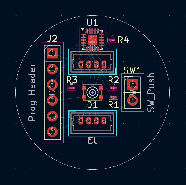
I'm just going to buy one of these seperately, but because I'm using the smd version of the chip, I can't just use the dip programmer. Instead, I've exposed a programming header, which isn't actually going to have a header mounted, so that I can connect it to program, and then seal up the case and not have ugly pins sticking out. It just uses spi, which wasn't too hard to wire up, but I am very much more used to i2c, so not as easy as usual (I keep on mixing up MISO and MOSI).
For the actual LED, there unfortunately was not an easily accessible parts library online, so I quickly made my own symbol and footprint; Fingers crossed that it works fine.
Anyways, here is the finished schematic, I'm going to work on the pcb for around another hour, and I'll report back here where I get to.
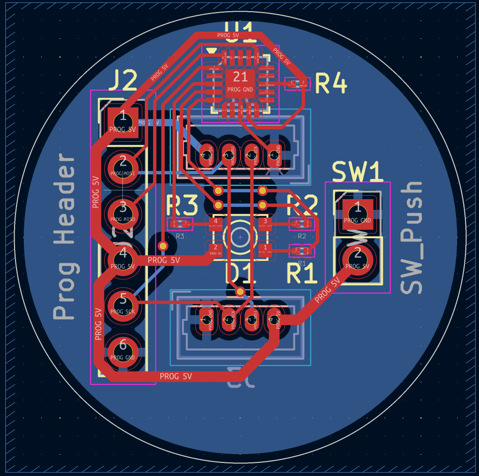
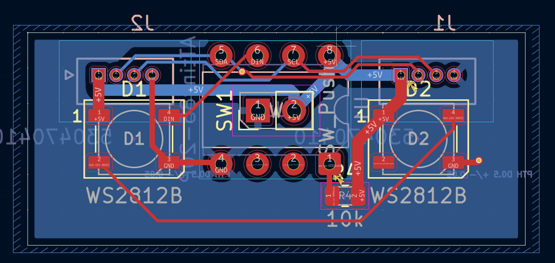
PCB Routing progress has been made! I layed out all of the components (after realizing that I also needed another connector for passthrough, which I quickly added).
Then just some quick and dirty routing.
And boom, pcb done! I got a quote from jlcpcb, and in total, for a run of 5, its \$26.69, so ~\$5.34 a piece. This isn't terrible, but I have a feeling I could do a lot better if I hand assemble it, so I'm now going to try and redo the pcb with pure dip footprints, and I'll see if it's feasible to do it that way cost wise.
For this, I'm going to change the MCU, again, this time to an attiny85, given I can get them for a lot cheaper in dip format and I do know how to get them to work :)
Alright, I've redone the schematic, and as you can see, it's slightly simplified.
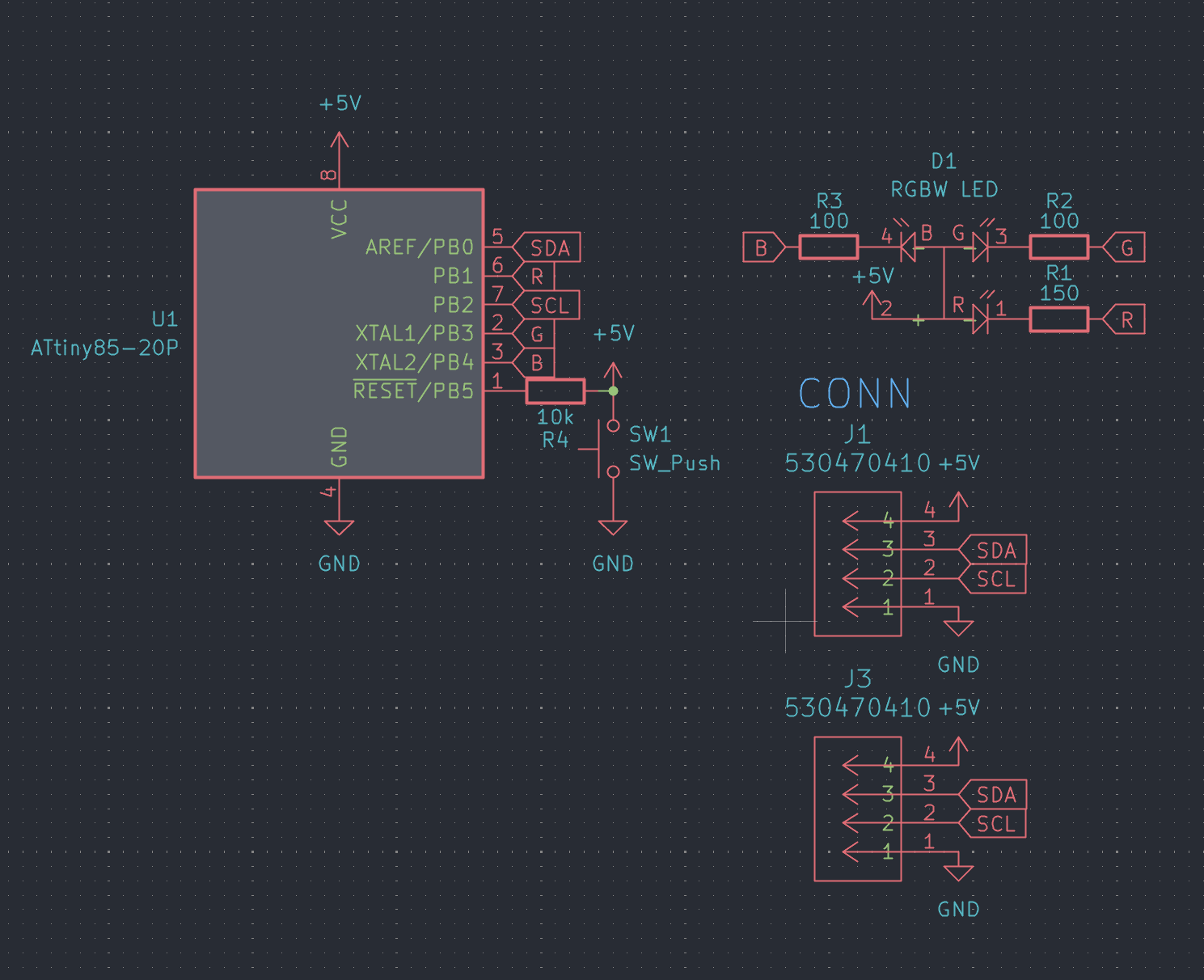
This is because I've opted to exclude the programming header from the board. If I'm buying the parts and then putting them on the board, I can easily just use the programmer in the way it was intended, just slotting in the chip and then soldering it after it's already programmed.
Time to build up the pcb and then do the bom.
*Side Note*
I've already got a bunch of rgb leds leftover from a previous project, so I've redone the schematic and footprint to use those instead, I'll try and find the source I purchased them from originally for anyone building this later :)
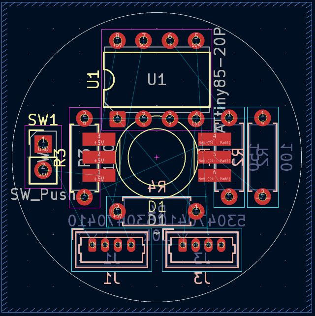
My god this was painful to all fit on. I've put all the resistors on the back side, and the chip and led on front, but I might move the chip to the back side as well later, just to help with even light, but I think it won't be too much of an issue to bother.
I had to add some margin of error on the led, as I'm unsure of the exact dimensions, even while I can measure them, I'm not particularly confident in my measuring skills, so I added a bit of a margin just in case.
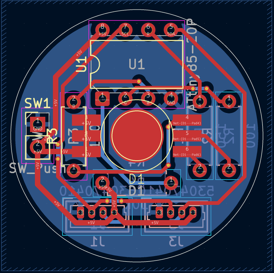
Routing it was almost even more painful than placing the components, but it's done now, looks clean enough, and hopefully will be a bit cheaper.
Speaking of, its cost breakdown time!
| Item | Cost |
|---|---|
| PCB | $0.42 |
| MCU | $1.76 |
| R's | $0.24 |
| Molex | $0.50 |
| LED | $0.24 |
| Misc | $0.30 |
| ----- | ----- |
| Total | $3.46 |
That's not bad :)
Misc costs include e.g solder, shipping (accounting for batch ordering) and random wears and tear.
That concludes my work for today, I'm going to 3d print a little test which I'll talk about tomorrow, but for now, goodnight!
Time Spent: 4 Hours
Stagekit - Journal 4 - 17/06/2025
'Ello poppets!
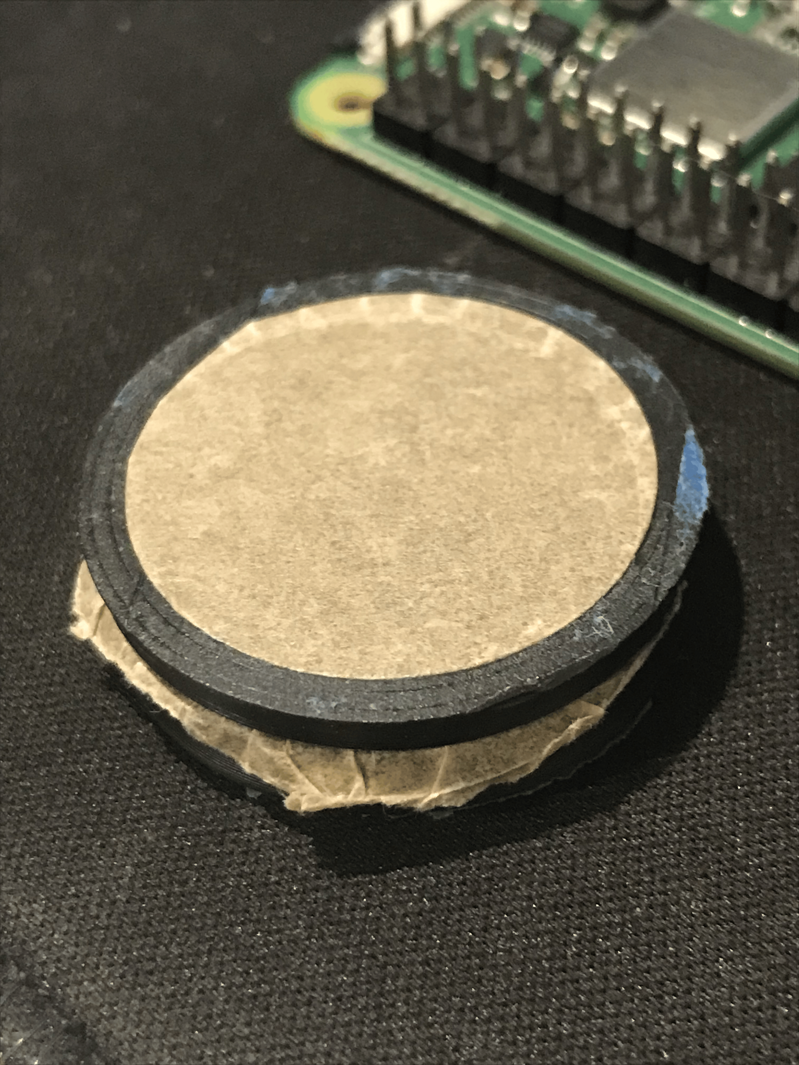
Today I've been working on the case for the rgb par so far, and have got what I would consider a mostly finished model, but first, the afforementioned 3d print.
The 3d print I made yesterday was a little test for a mechanism to add a bit of diffusion paper to the light.
For those unaware, a diffuser helps with spreading the light out a bit more:

This should make it look a bit less like a single led and more like light is coming flatly from the entire front surface, but I don't have too high hopes lol.
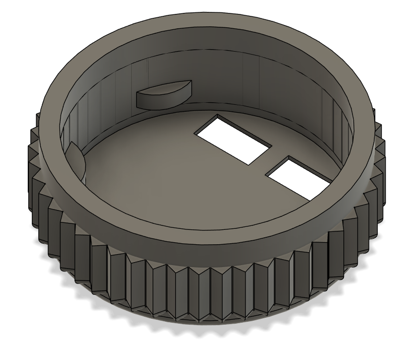
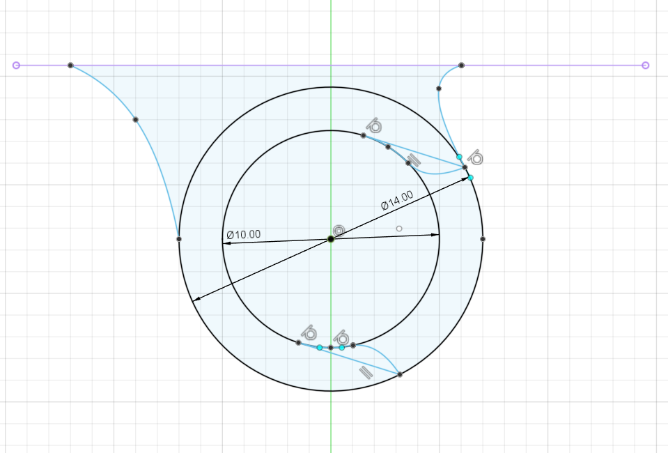
For the actual mechanism to hold the diffusion paper, its a simple press fit ring that clamps down on the paper, pulling it taut and keeping it secure. This hopefully will also hold the entire assembly together with only a press fit, which should make it easily maintainable.
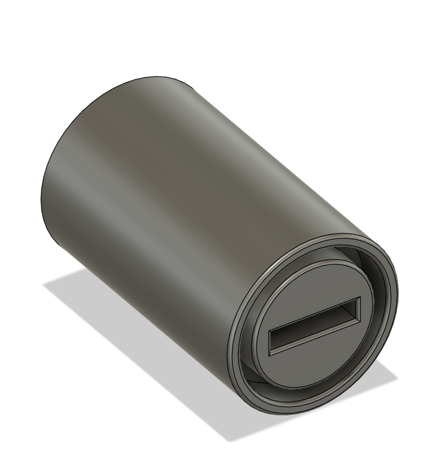
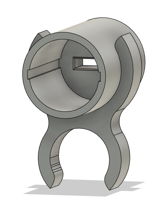
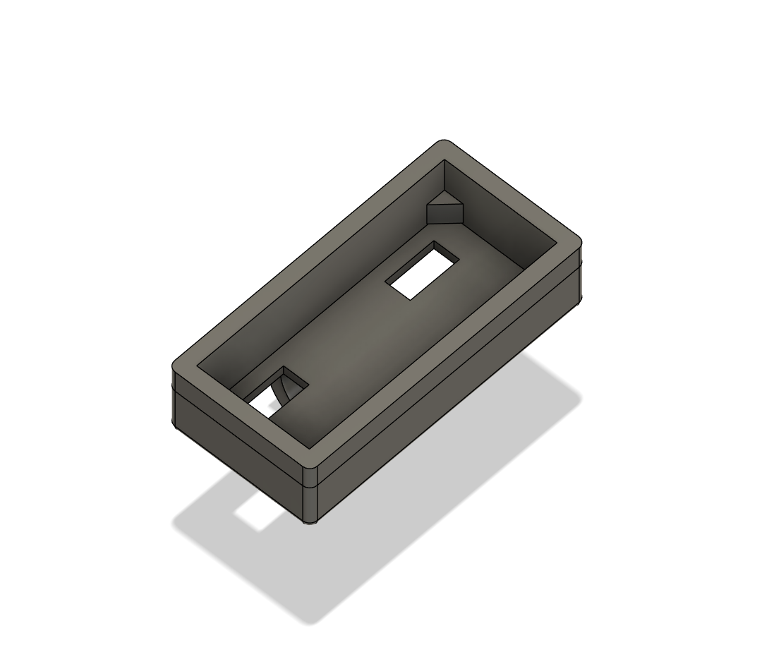
Onto the actual case for the light I guess.
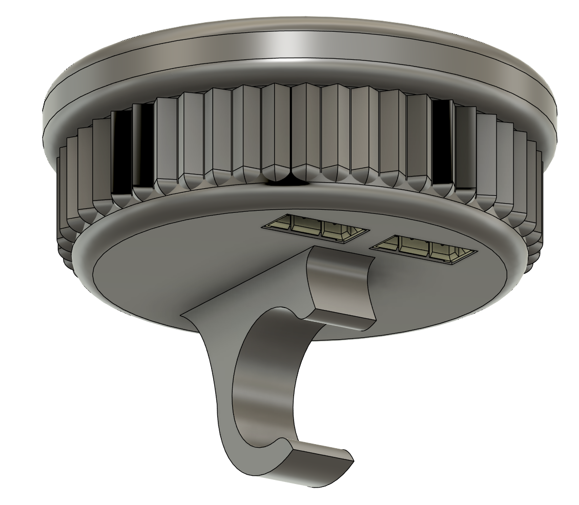
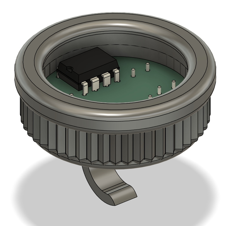
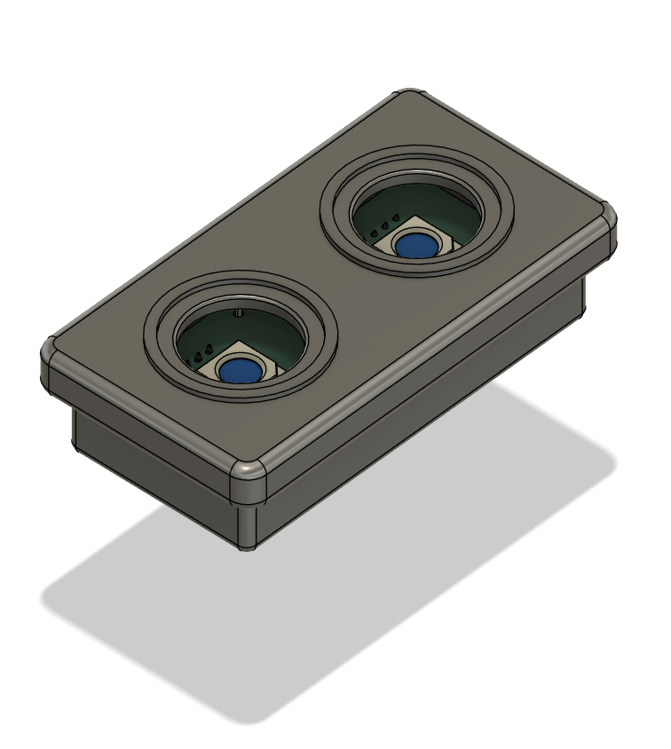
The bottom case
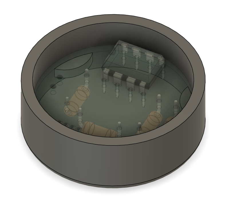
I designed this so that the pcb can just sit on the little thingymabobs and it will be the right height so that the ports on the bottom fit well. Hopefully it won't fall out, because there are no screws or anything holding it down, but the fit is tight enough it should be fine.
I also decided to add some decorative little heatsink thingys, just because I see them on a ton of lights and they add some visual interest to otherwise a plain cylinder.
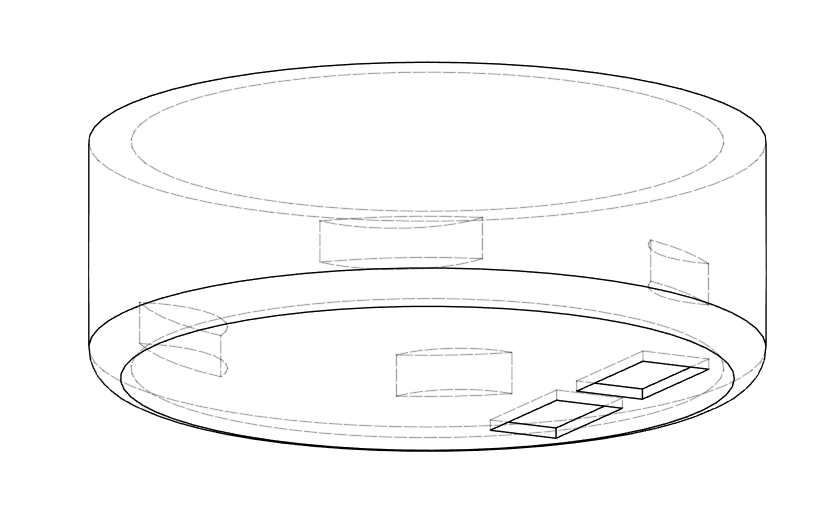
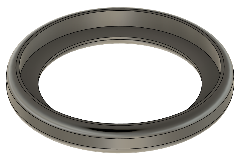
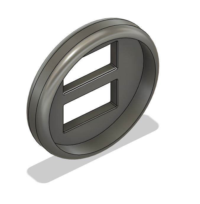
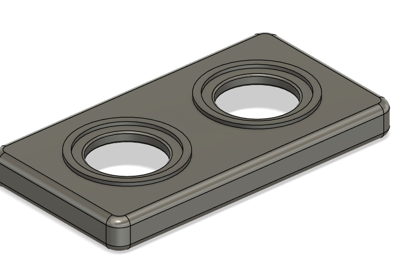
The top case
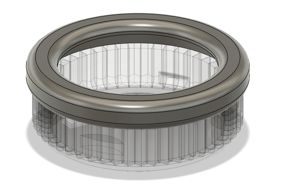
The top case is again the same mechanism as the 3d printed one earlier, just a simple hoopish structure that is a press fit over the top of the bottom case.
Not really too much to say here, its got a little lip to hold the paper more taut, but nothing too interesting.
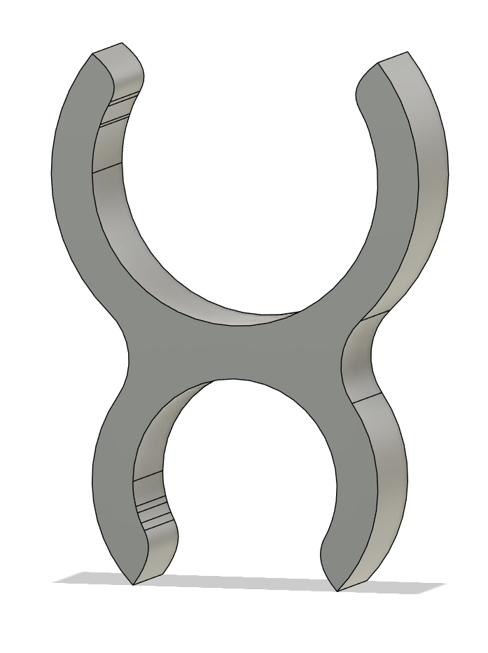
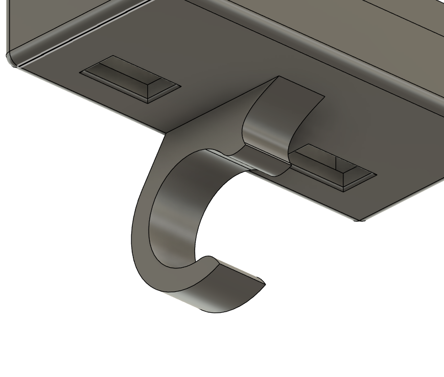
The clamp
I'm pretty happy with the clamp.
Its based around the 10mm cylinder that is the main chords of the trusses, but it also has some little lips so it won't fall out and should satisfyingly clip onto the trusses.
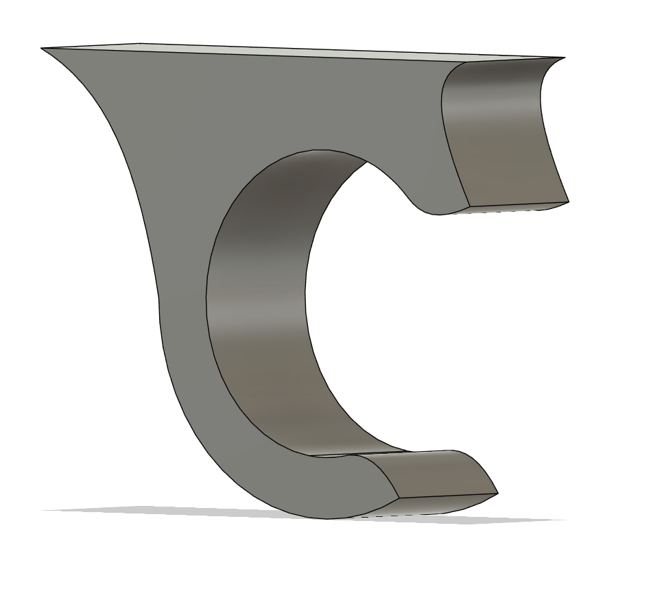
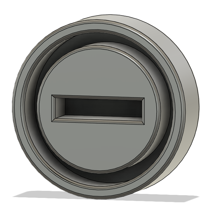
Overall, I think the case turned out looking pretty decent. The clamp part looks a bit ugly, but that can't really be helped without more resources than I'm willing to spare.
The dimensions of the light do differ from the real equivalent slightly, ending up having a dimension of 36x36x13.5 (excluding the hook), which is a bit larger than the desired 25x25x10, but should be close enough to scale to look good.
That's me for today, I'm taking a slight break for the rest of tonight because I'm hellishly tired and have homework to do, but tomorrow my goal is to make one more truss piece and design the schematic and pcb for the rgb tube.
*Note*
Just quoted the parts on jlcpcb, $0.66 for all the 3d printing
for one with standard resin.
Time Spent: 3 Hours
Stagekit - Journal 5 - 18/06/2025
The pixel tube I'm trying to model mine off of is the Astera Helios Tube, but its dimensions are frankly a bit much to do at 1:10 scale.
They have a diameter of 42mm, which would be 4mm at scale, which is very much too hard to do. Because of this, I'm scaling it to Ø8mm x 103mm.
The schematic
The schematic is pretty similar to the par, but instead of an rgb led, it has six neopixels, just to save on mcu pins. This means I still could use the attiny85a, which is nice as I could reuse like 90% of the previous schematic.
Overall, the schematic took like 30 seconds lol.
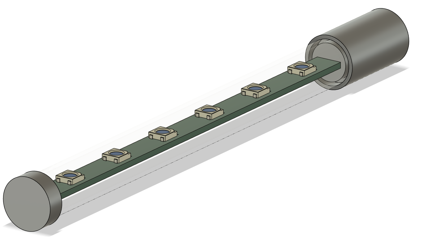
The PCB
The pcb was around the same, but I had difficulty decided the length of the light overall. I wasn't sure if I wanted it ~1m or ~2m long, but I eventually settled on around 1.6m (~150mm).
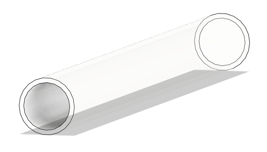
The Case
This was much harder than the previous design, as I had to settle on how I was going to diffuse the light, but after considering acrylic tube with diffusion paper, silicon tubing, and pmma, I decided on pmma tube.
PMMA is a form of acrylic but is much more often available as a frosted translucent material, which is perfect for what I need.
I eventually came up with yet another design consisting only of press fits (hopefully this doesn't come back to bite me) and voila, case done.
Sorry if this journal was a bit lackluster, I'm writing this a couple days later and I'm still feeling pretty sick.
Time Spent: 4 Hours
Stagekit - Journal 6 - 19/06/2025
Today was focussed on updating boms, and making the blinder
Guess what day it is!
Thursday, but thats besides the point. Today is BOM day!
I'm going to go through the lights I've done so far and make up some nice boms for them so I don't have to do them all in one chunk at the end.
Starting off with the rgb par, I tried to arrange it so that all the parts came from aliexpress, but unfortunately I couldn't find any of the molex connectors I need (i am finding a lot of the jst sh line... oops), so I've decided to go with lcsc for them. However, I've come to an overall price of \$3.025 (excl shipping), so thats something.
For the rgb tube, its a similar story, everything possible from aliexpress except the molex connectors again, and it came out to a unit cost of \$4.015 (excl shipping), which is actually excellent.
The blinder
Blinders are very cool lights. They blind, look cool, and yeah... Blind stuff cool!
I basically copied the schematic from the rgb tube, just using two neopixels instead of six, so that was super easy.
The pcb was also super chill with routing and layout, just was a bit of a squeeze fitting the attiny.
For the case, I did another press fit, and just made a two part case which the pcb slots into (hopefully tight enough it doesn't bounce around), and added some holes on top for light and then the clamp.
Again there will be a little bit of diffusion paper that slots between the top and bottom case, so it won't look as ugly in the final light.
Following finishing this, I quickly made a bom for it as well, coming in at \$2.985, which is not bad at all.
Thats me for today, tomorrow i'm working on finishing up my keyboard for submission, so I'll probably do more on sunday.
Time Spent: 4 Hours
Stagekit - Journal 7 - 22/06/2025
Today I'm going to be working on the start of the first moving light, and for this (maybe stupidly) I'm going to try and tackle a two axis light (pan and tilt), so we'll see how that goes.
After much deliberation (and I mean much, I spent like 6 hours researching), I've come to the conclusion that it is practically impossible to make this light to scale while including hardware like motor drivers, the actual control chip, and the motors themselves.
As I see it, there are a couple possible solutions: A. Have the driving and control hardware in the seperate enclosure somewhere else (maybe behind or underneath the stage) B. Have the motors not actually move C. Have my light at double or triple the scale of the actual lights.
I don't really want a static moving light, so option B is out of the question.
For option C, I'll just let you look at the following diagram:
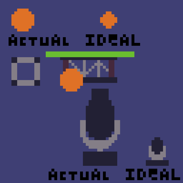
Yeah, this might not be a great option either...
With option A, the base and yoke can be as small as I can get the motors, and the actual head can be tiny, so there are much less problems with scale.
In that case:
Motor selection
I spent several hours hunting through different types of motors, and I've come to a conclusion, they're all too big :(
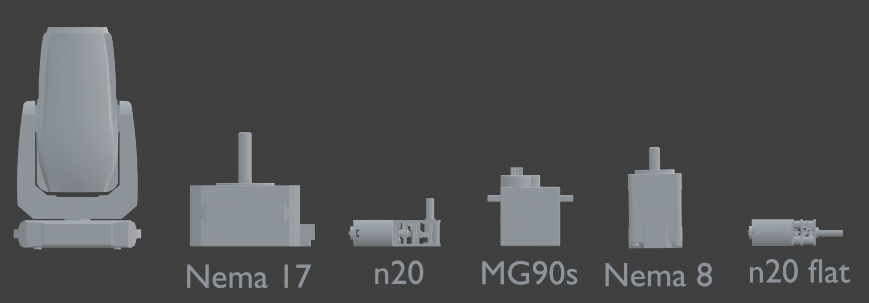
However, I'm willing to compromise and go with one of the n20 motors, as they're still a decently ok size.
For actually turning the yoke (the U-shaped part f the light) I obviously can't have a different direction for the motor, so I'll need some form of gearing.
First of all, with the n20 right angle:
I would prefer to not have the yoke directly attached to the motor, as then the base gets very wide, so what I'm thinking is gears, essentially something like this:
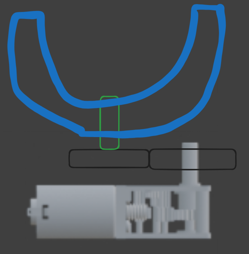
For the n20 flat, I was considering something akin to how the microwave plates work, where they spin around on rollers and stuff.
Basically this:
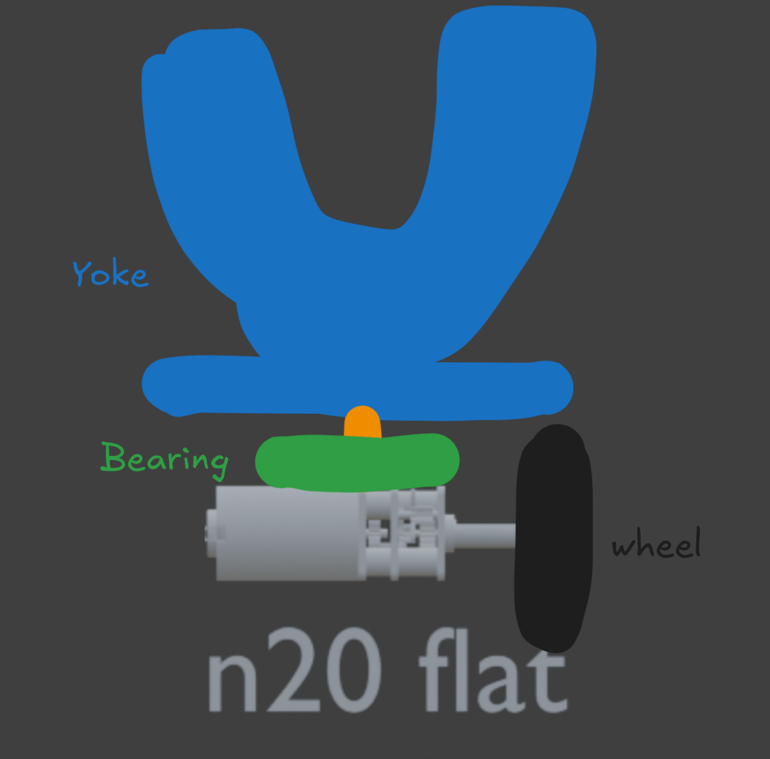
Tbh, the first one will probably work better, so i'll go with that one.
Unfortunately, its getting late, so I'm going to continue on with this tomorrow.
Time Spent: 1.5 Hours
Stagekit - Journal 8 - 5/07/2025
Oh god, been a while :O
I lost like all motivation for doing anything for a week because school, rockquest, and generic other crap I've had to deal with, but now I'm back, and more productive than ever! (not really).
Today I've so far been working on some firmware and connectors and stands for the truss pieces.
Firmware
Alrighty, I've mentioned this before, but I'm using i2c to communicate between a bunch of devices. Each light has an attiny85 in it (at the moment, need a different one for the next light i'm working on), which is set up as an i2c slave, each with its own address. Each light constantly listens for messages broadcast to its address from the master controller, and when it recieves one, it updates the lights based on the data it recieves.
I chose this approach because if for some reason the master goes offline or some data is lost, it doesn't stuff up the lights visual display. I admit that this might be slightly overkill, I was kind of just copying roughly how the DMX protocol does it, but thats also built to not plunge stages into pitch black if a console crashes, and given mine is just a model, it's probably not as vital of an application, but regardless, nice to have.
The actual firmware wasn't too bad. I made a little boilerplate code which sets up the i2c and provides a function that should be modified to change the light, but honestly theres not too much to do.
#define I2C_SLAVE_ADDRESS 0x3   // The address of the light (can go up to 127)
#include <TinyWireS.h>          //the ATTiny Wire library

// The data format uses 5 bytes in this example, but I have a custom definition for each light
// Byte 1 : R
// Byte 2 : G
// Byte 3 : B
// Byte 4 : PAN
// Byte 5 : TILT

byte data[5] = { 0 }; // Data is just stored in a byte array;

void setup() {
  TinyWireS.begin(I2C_SLAVE_ADDRESS);
  TinyWireS.onReceive(receiveEvent); // whenever data is received, call receiveEvent();
}

void loop() {
  TinyWireS_stop_check();
}

void receiveEvent(int numBytes) // numBytes is the number of bytes received
{
  // If the number of bytes we receive doesn't match the data format, we have a problem
  if (numBytes > sizeof(data)) {
    return;
  }
  for (byte i=0; i<numBytes; i++) {
    data[i] = TinyWireS.read();
  }
  // Update the visual display of the light
  updateLight();
}

void updateLight() {
  // light specific code here
}
So yeah, I adapted that for the rgb tube, par, and the blinder, and it hopefully all works :)
Brackets / Base
Pretty self explanatory here as well, the base is just a thing that can attach to the bottom of a truss so it sits a bit more nicely on the ground, and the bracket just connects two trusses together.
Decently simple, so I'm not really going to go into the thought process here majorly, the only thing I really had to consider was the clearances on the holes, and I went with a 0.1mm extra clearance, which made for a decent press fit when I printed it.
More to come tomorrow :)
Time Spent: 3 Hours
Stagekit - Journal 9 - 6/07/2025
I've yet again been looking into the mini moving light, and holy crap, its getting very tough to get this for a reasonable cost. A lot of the issue is the yoke motor, which spins the actual light part of the light. I'd need to spec a timing belt and pulleys, and then somehow pass power and data through to it, which honestly is far more work than I think I could feasibly achieve in a single design iteration, which is kind of a requirement due to how highway is set up + shipping costs. So unfortunately, I'm going to have to exclude the moving head from this project :(
However, that doesn't mean I'm not going to have any moving elements, I might do a light with only a single axis of rotation, like a roller bar or something.
Unfortunately, I have exhausted my time today just trying to prototype out the moving head, leading to several failures due to various reasons, so not much actual progress to show today.
Time Spent: 2 Hours
Stagekit - Journal 10 - 10/07/2025
Been a while again :(
Getting back on the grind today and am going to design some set dressing elements for the system. Quick list of what I hope to get done: - Modular stage platforms - Stairs - Truss mount line arrays - Generic Stage boxes - Mini consoles / racks - Drumkit - Amps - Modular Stage risers
I might end up adapting some online content as well, for people, etc.. but for know I think this is a decent list of parts.
Modular stage platforms
The modular stage i'd like to be something which just clickes together, and can be slightly elevated off the ground so you can run cabling, etc through it.
In order for them to connect together, I could either go with a literal clip system, similar to how the lights clip onto the trusses, but when considering how the pieces will be printed, the clips would have to sit below the stage surface, and that would require supports to print, which is probably not the most efficient. Also, clips degrade over time and can snap relatively easily, so i'm not going to go with that for the system.
The next idea I thought of, and the current approach I'm building them with is a kind of jigsaw approach. If we ignore the feet of the stage for a moment and only focus on the top surface of the stage, each piece has extrusions and intrusions which slot together, as shown in the image below.

The important thing is making sure they can all slot together properly, but I think the layout of pins I've got is reasonably optimal.
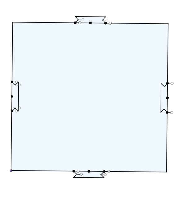
Heres the inital shape sketched out, obviously not 3d yet and it doesn't have rounded holes or extrusions, but you can get the general idea.
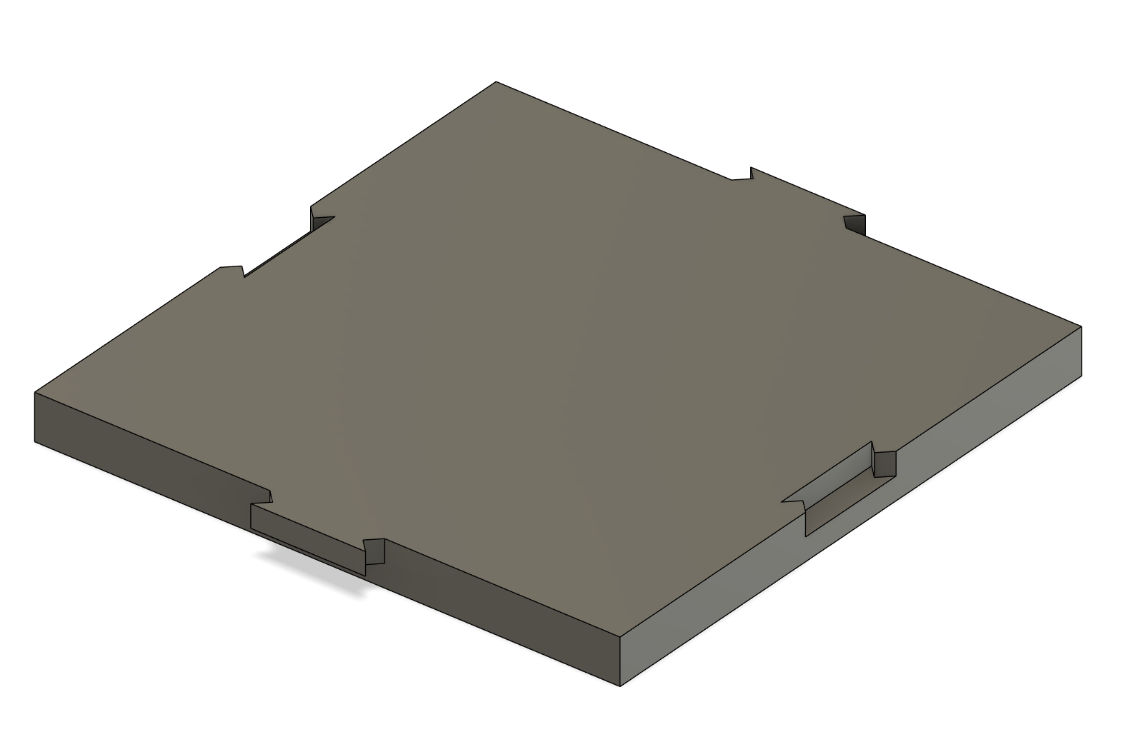
And now 3d. I've made it so the slots and stuff only are half the width of the platform, which should hopefully keep it a bit more consistent at staying together nicely even on uneven surface, and also make it just nicer to snap together. With the puzzle bits being on the top, the stage surface does get a bit inconsistent, but this isn't a major problem, as the stage being perfect isn't really a big deal, and stages in real life often have similar looks, also being snapped together (with a different mechanism of course).
![]()
Alrighty, now it's got feet, so just need to round out the jigsaw pieces slightly and then I'll do a couple test prints.
![]()
Annnnd done :) Printing it, due to my amazing design skills, it needs no supports, and each piece prints in around 45 mins on my printer w/ ~8g of filament. Not too shabby if I do say.
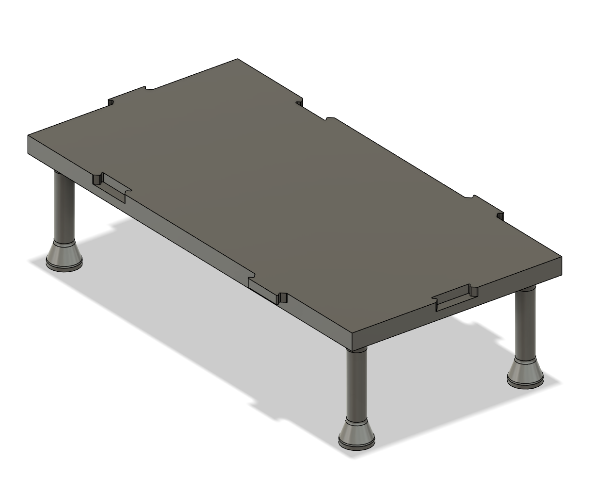
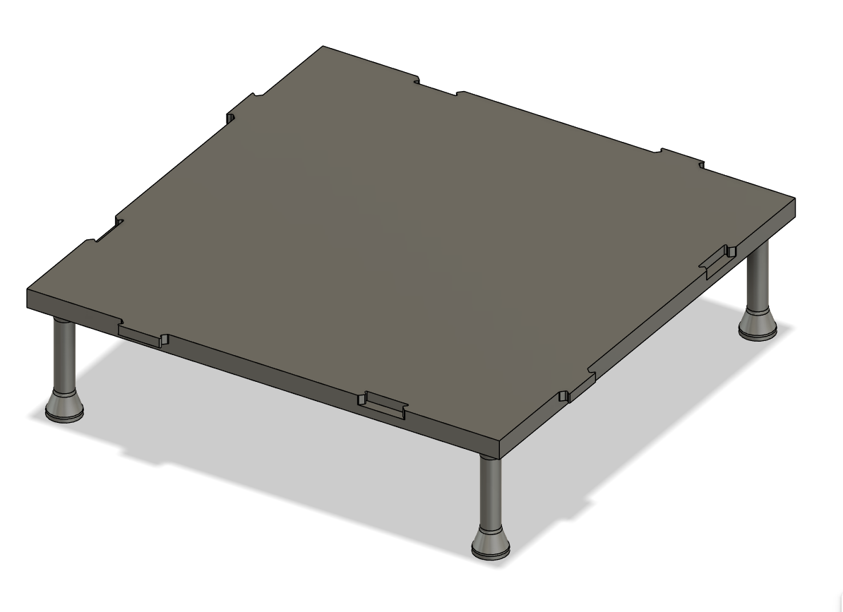
While waiting for the print, I quickly made a 1x2 and 2x2 version of the platform, all with the right puzzle bits (i hope).
Also, stairs.
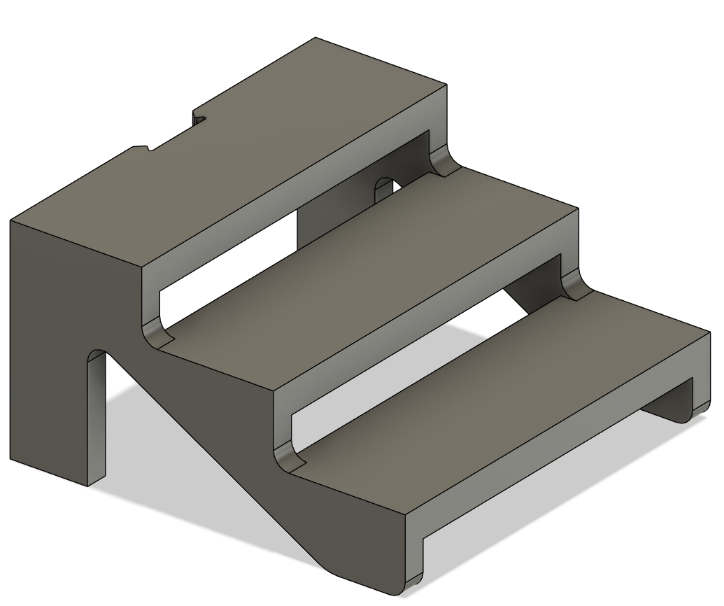
Prints finished now, and I've got a couple problems. The legs on the thing are super flimsy, I snapped two just getting the two pieces off the build plate. The other thing is the clips are super small, and my 3d printer doesn't have enough resolution to print them properly, so they became more rectangles than clips, and the clearance was kind of cooked. To fix this, I'll probably just increase the size of the clips and make the legs that same thickness at the bottom all the way up.
For the stage risers, the stage can double as a riser, especially given their relatively low height.
Amps, Racks, and other stage props
I'm going to be using blender to design these elements, as I find the actual modelling much quicker and easier in blender than fusion for detailed parts.
Amps
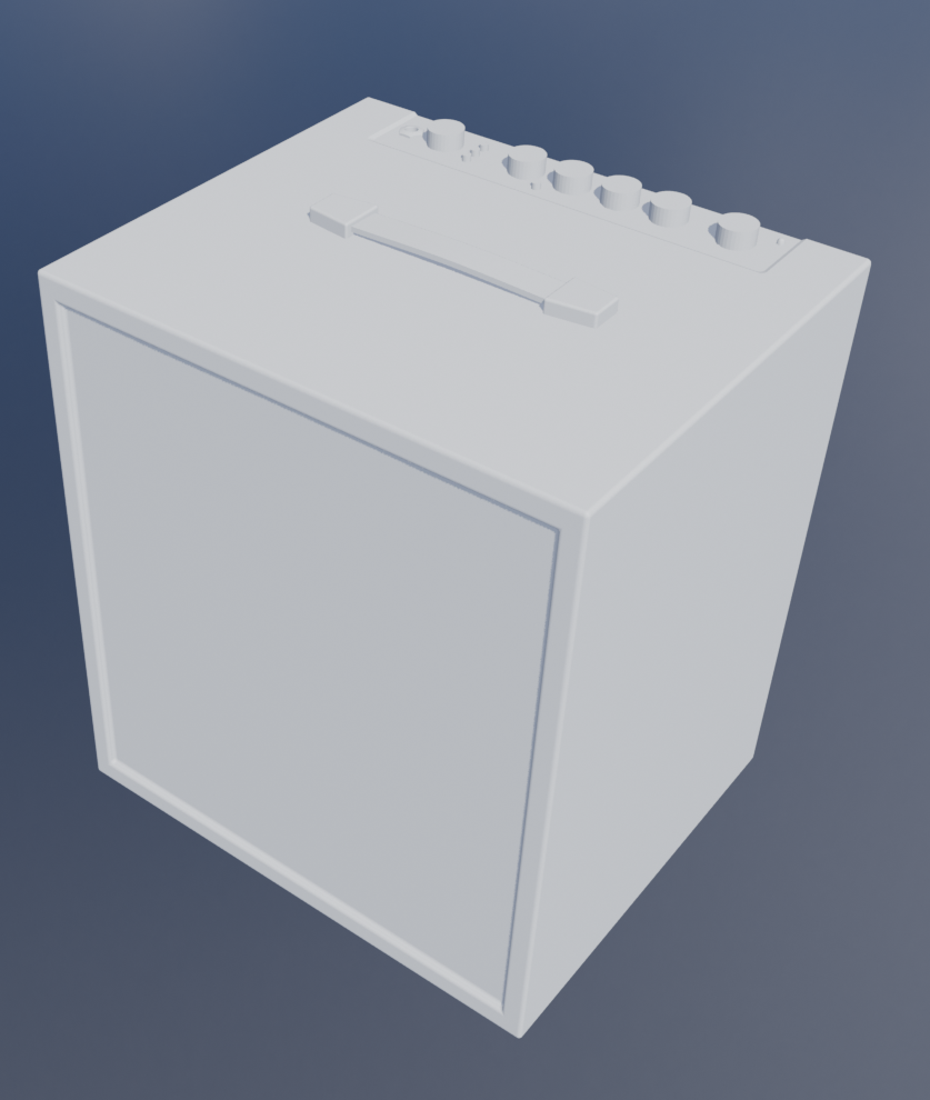
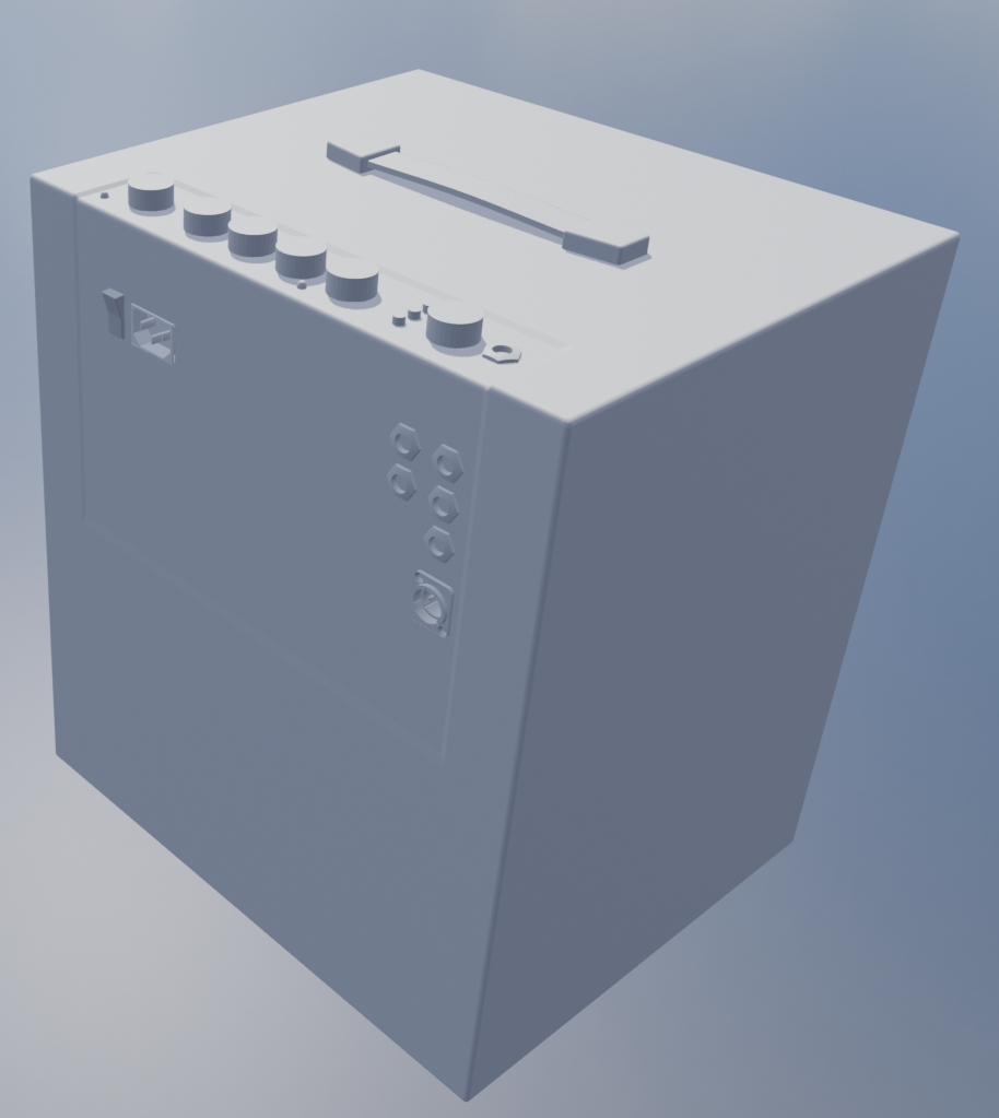
I'm going to model a few amps. Being a bass player, I'm absolutely going to do the classic Ampeg 8x10 stack, as well as a combo modelled after the Fender Rumble 100 and also my favorite little combo, which is a Ashdown ABM 600 with 1x15 and a 4x10 cab.
First up, the ashdown head.
Next, 8x10 cab:
And then, the rumble 100.
Markbass 1x15 cab:
And finally, the 4x10 cab:
Guitars can just pretend to be basses and use the same cabinets and stuff, so don't need to do many other amps or stuff.
Some of the details might be a little fine to 3d print, but I think it should mostly be ok, as they're all on the back anyway (mostly).
Tomorrow, I continue :) (actually the day after tomorrow if you're going by the journal date, i took a break between the stage and the amps)
Time Spent: 4 Hours
Stagekit - Journal 11 - 13/07/2025
More 3d modelling today!
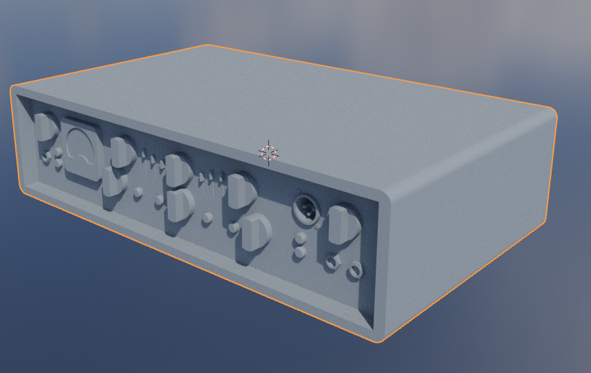
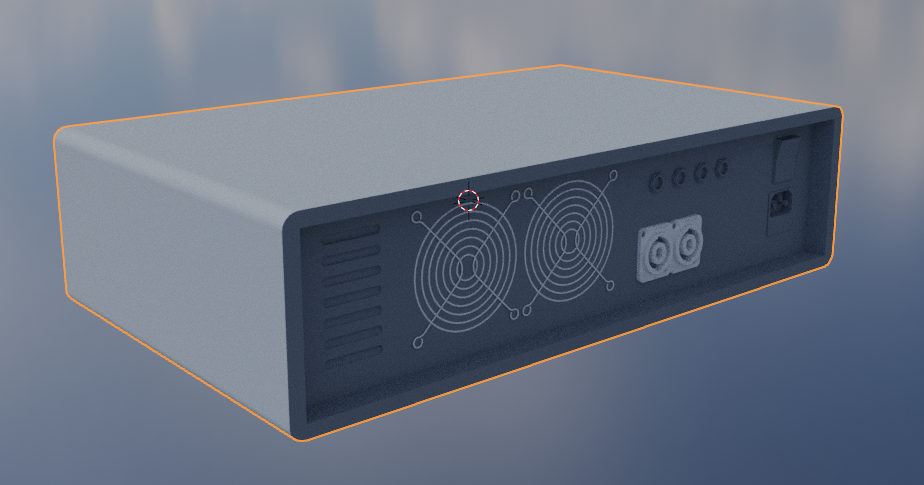
First up, just a generic roadcase:
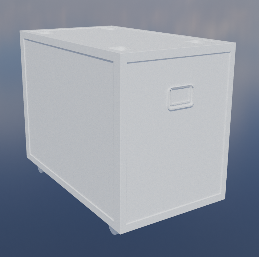 Not perfectly accurate by any means, but I think it'll be adequate for the models.
I really can't be bothered do many more 3d models :sob: but i'll struggle through and make a couple more things.
Not perfectly accurate by any means, but I think it'll be adequate for the models.
I really can't be bothered do many more 3d models :sob: but i'll struggle through and make a couple more things.
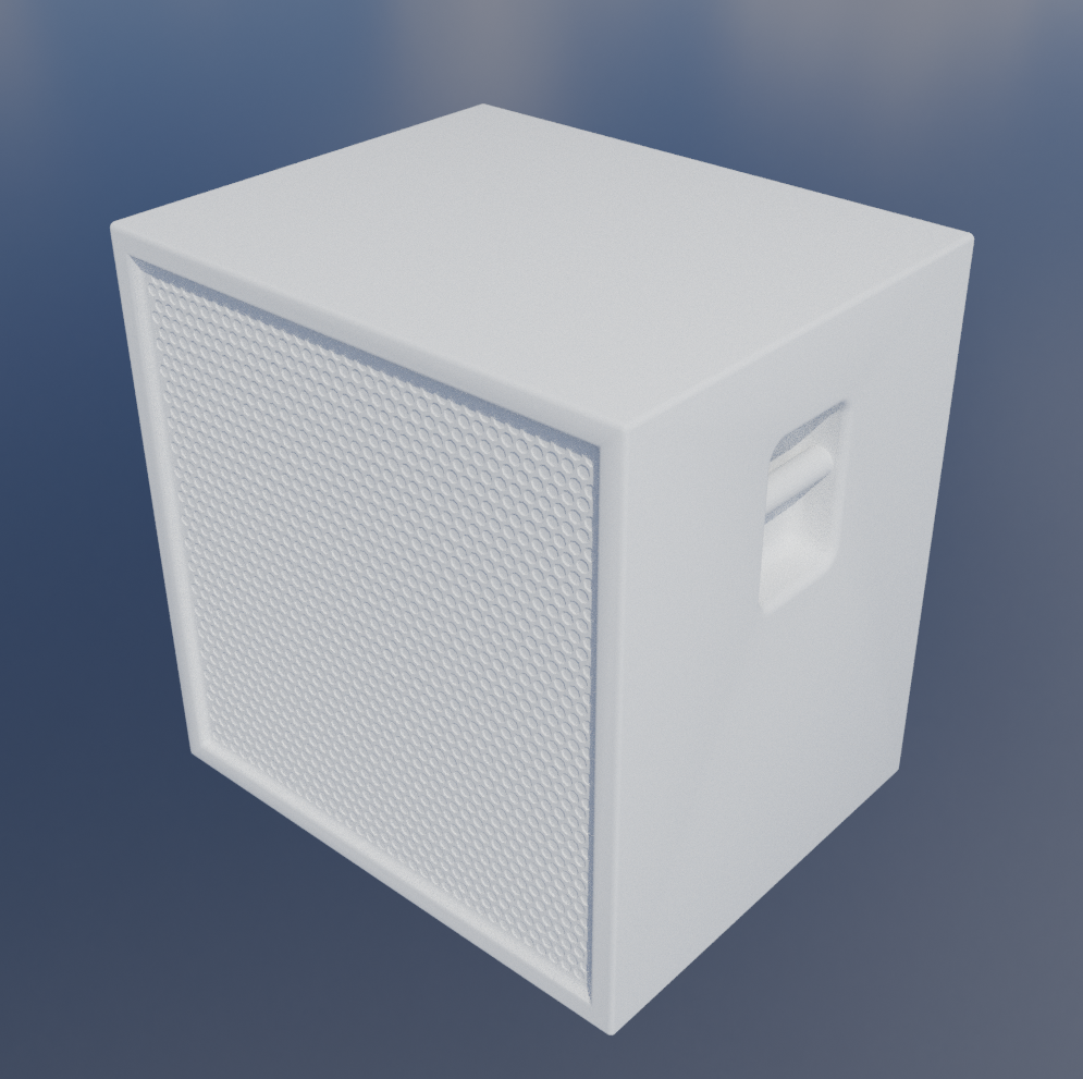
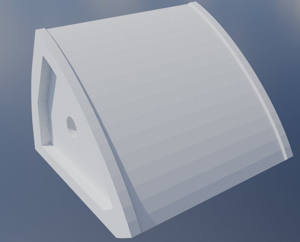
Wedge monitor:
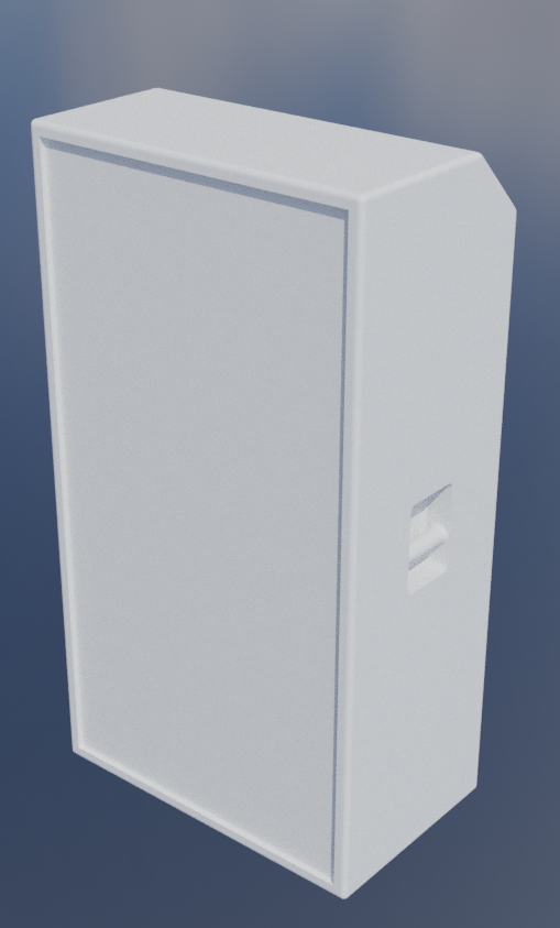
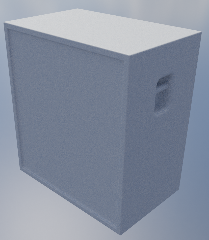
Subwoofer:
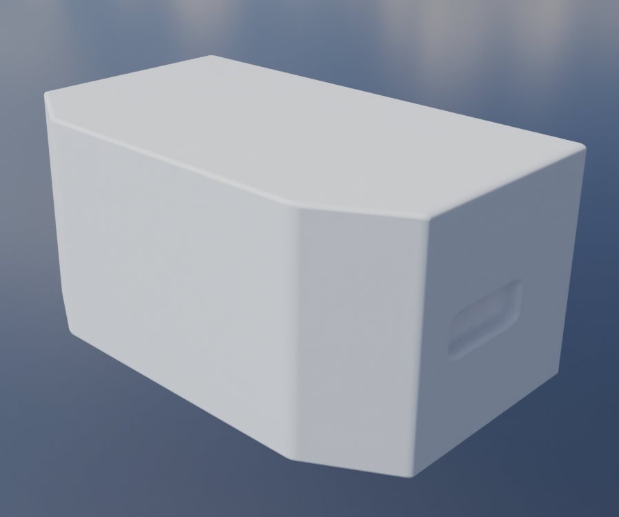 Note: i wasn't super lazy here, this is just how basic it looks lol
Line array:
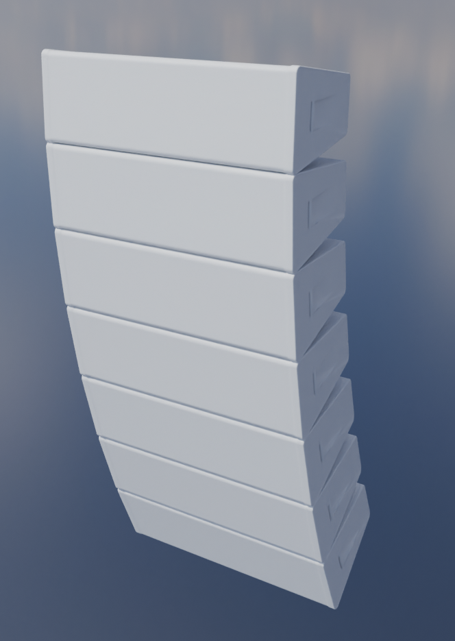 I have no idea how people will print this or how it'll attach to the trusses and stuff :shrug:
Alright, I'm gonna call that enough models for now. I quickly put together a little scene with a bunch of objects in blender to test the scale and stuff, and I think it came together pretty well. I got a drumkit and guitar model from online, but they're not really in a 3d printable state so I might make my own eventually.
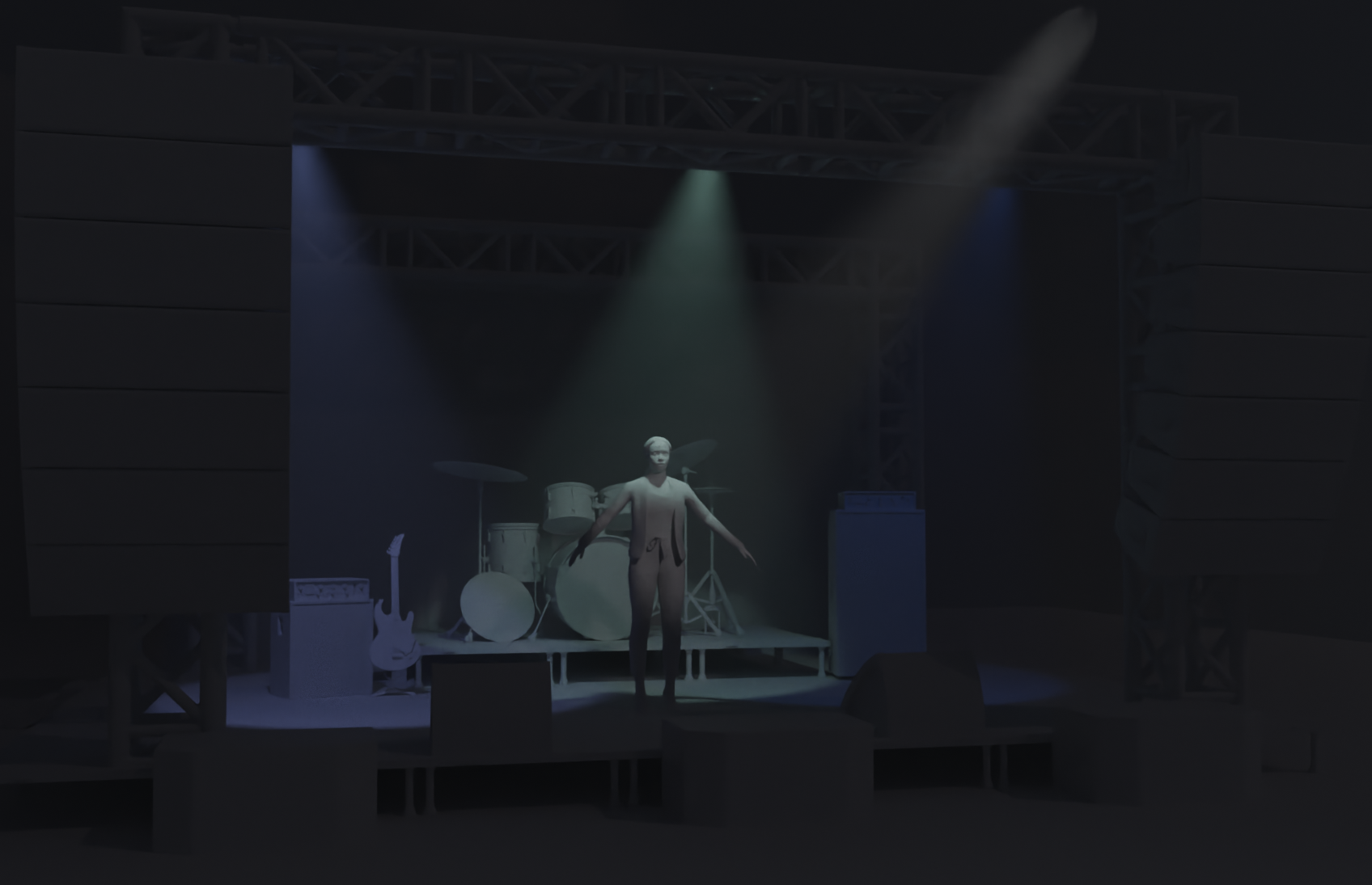
As you can see, the line arrays are perhaps a bit too big for this small of a stage, and having no actual reference for the drums and guitar, i just scaled them by eye, but I'm pretty sure they're a bit off. Otherwise, I'm pretty happy with how its looking.
Next up...
I'm just going to quickly cover what the rest of my goals for this project are. I'm going to aim to have this finished in the next 4 days, and here's what I plan to do:
- Tidy up 3D Models
This just involves sorting out clearances, making sure connections are all proper, and making the 3d models I just did connectable (the line array :skull:)
- Swap from picoblade to jst sh
Pretty self explanatory, just changing the plug format as jst sh is much more readily available on aliexpress.
- A few more 3d models
I pretty much just want a curtain for the back of the stage and some gates / barriers to go sidestage to emulate more accurately an actual stage, because light spill is a thing.
- Maybe another light
3 types of light isn't massively impressive yknow, unfortunately, I've already covered the general static light roles, but i could potentially do a little led matrix or bar type fixture. I'm a bit reserved on making more bar / neopixel type fixtures, because 90% is just copy paste from the other lights, which doesn't really feel super fun, but whatevs ig. A moving fixture seems out of scope given the time constraints I've set. I might do it as another highway project addon for like a four or two point project later down the line.
- A nice readme
I really want to focus on making this project accessible and easy to use. Thats part of the reason I chose to do only tht components (mostly) for all the lights, and why I'm only using 3d printable parts. A good readme should help make it easy for other randos to get it up and running quickly and easily.
- Main control firmware
As stated earlier, this is running off a rpi zero 2 w, but I am yet to write the firmware to handle the conversion from art net to my custom format. I'll probably just do this while waiting for components to ship.
Time Spent: 5.5 Hours
Stagekit - Journal 12 - 15/07/2025
Alright onto the list.
Picoblade vs jst sh: Turns out a bunch of picoblade connectors are just sold as jst on aliexpress, even though they're clearly picoblade. I've found some for cheap and so picoblade can stay :)
Next up, 3d models:
I'm aiming to have clearances of around 0.1mm for all the 3d printed parts, which should hopefully still allow for a reasonable press fit. Just went over all the truss and case models and fixed this, not too bad.
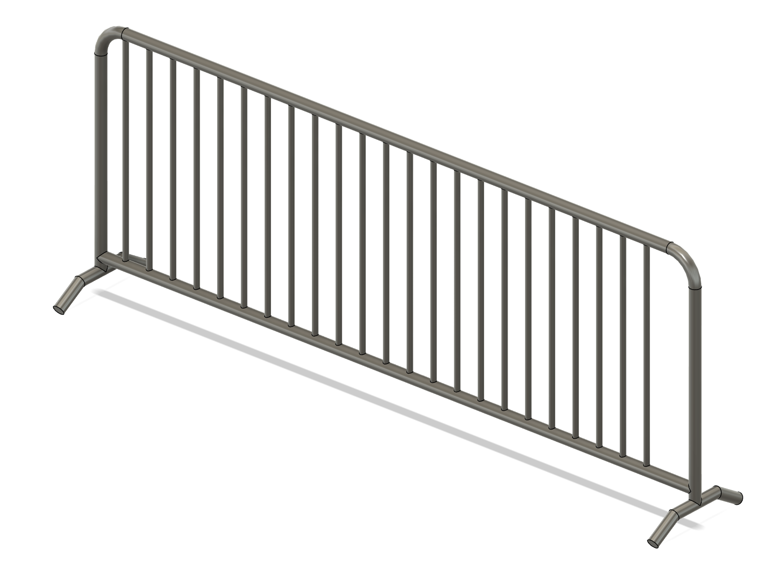
Item #3: More models: I quickly whipped up a little fence in fusion 360, but the curtains proved to be almost impossible to get looking good and 3d printable. I might just resort to proper fabric for this one lol.
Vierte: Readme! I've done most of it, just finishing up the boms now. I think its pretty decent, but improvements are welcomes :)
Lastly: I'll make another journal post when I get around to the controller design, but again, I'm going to submit first and work on this as it's coming.
Just tidied up all the stuff and got the final quote for the system! Submitting now :)
Time Spent: 4 Hours