
Keyboard With Utility
---
title:
Keyboard-With-Utility
author: DHMango
description: A mechanical keyboard that has a screen and you can plug a mouse into
created_at: 2025-05-23
Total time: 15hr
May 23: It begins. Some planning and schematic work.
After thinking for a little while, I settled on a mechanical keyboard with an LCD and some USB ports. This will be my first time designing a PCB, and I don't want to choose something to diffifult, but I think this should be doable and pretty cool. To start, I looked online for similar designs, and found some things I can potentially use as reference. (Pi Pico Keyboard, PCB Keyboard, and USB hub). I decided to use KiCad to design the PCB because it seems pretty widely used is free.
I am going to use a Rapsberry Pi Pico because of its small form factor, low price, and popular use in similar projects. It looks like if I want to be able to split the USB input, I will need to have the Pi Pico connected downstream of something else, so I won't be able to use the USB connector it comes with. Based on the datasheet, though, I should be able to surface mount it onto the PCB and use the test points to make a connector. Looking online, it seems like I can apply solder paste to the PCB, place the Pico on, and heat it up with a hot air soldering gun. Unfortunately, these cost around $30 so I may have to find some workaround. It seems kind of janky, but it might be better to just use a cable that plugs into the pico but is attatched internally. If I can't get this to work, I may have to abandon the extra ports :(
After spending a little while trying to input pcb elements into kicad, I decided to just use EasyEda, because it is also free, seems easier, and many of the LCSC components easily available. Unfortunately, I am having some problems understanding the pinout of the USB-C connector which I want the keyboard to connect with. I have to go to bed now, but this is what I have so far.

Today, work has been somewhat slow, but I think it should start to go better once I have this software figured out.
4 hrs
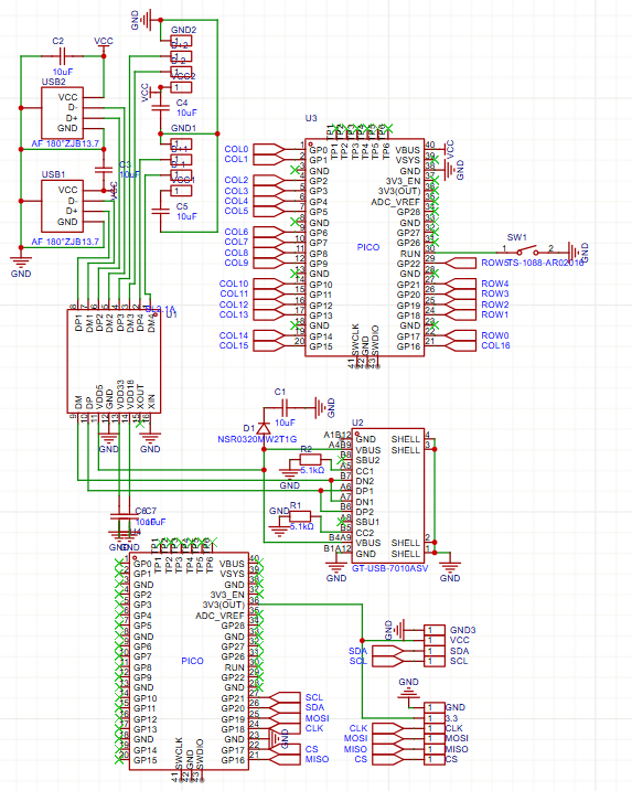
May 24: Schematics
Today I want to mostly finish the schematics, at least for the keyboard part. Last time, I forgot to save my schematic, but it is fine, because I only made slight progresss. Since I want to use USB-C, I needed to figure out what the special pins are for. It seems like many of them can be shorted, but CC1 and CC2 need to be pulled down. Next, I looked on the components catalog and found what I was looking for earlier: 4 pin wire to board connector. This should let me plug the Pico in without needing the test points. I made a test PCB to see about specific parts, and everything is fine except for the Pico, which it can only make the pads for (assembly costs +$50), so I will solder it on manually. I also added the USB-A ports for mice and etc.. It is taking a while to find the correct components and figure out how to read the spec sheets, but I think I am getting a hang of it. This is what I have so far.

Thinking more about the display on the keyboard, I think that I will make it be a Now Playing
thing like this Spotify display
2.5 hrs
# May 25: Key layout
Now, it is time to make the keyboard. I used keyboard-layout-editor.com to generate a layout that I like. After doing some reasearch I think that I am going to use a slightly modified 75% keyboard with space for the screen that I want to add. I think I will use these keycaps because they look cool and are pretty cheap. They also support many keyboard layouts.
0.5 hours
June 22/23: The screen
After a long break for no reason, I am back to this project. I realized that the deadline is coming up, so I have to finish this.
Most of this project has been (sort of) simple up until this part for me. I want to be able to read my plugged in computers now playing
window. Using this, I am, hopefully, going to display song title, artist, progress, and album cover. I think the easiest way to do this will be sung the winsdk python library. I used AI (I know I know, but I'll re-write it myself later) to generate some code that downloads the media thumbnail, shows the artist, progress, and song title. This worked (after some modification), and I think this proves that it will be possible to send the data serially to the display. I'm probably going to send the image and text to whatever microcontroller I use, and process it with this TFT display repository to show it. I think I might use a cheap ~1.5 in lcd like this one that has a ST7789 chip and uses SPI for the picture, and a little OLED for the text and stuff like this or this, which are both controlled over I2C. I could also choose something like this larger one to display everything. I will probably control these using another Pi Pico so that the keyboard function doesn't break or slow down if this little screen does. I am glad that I found solutions for this because I was worried I wouldn't be able to get this to work.

1.75 hours
June 27: Nitty gritty
I looked at the displays again and I think I will use one display for the image and one for the text. I will probably use this for the image, and this for the text. I will control these from some RP2040 board and use this library for the text and this one for the image. I think i will use another Pi pico. It took a little while to find documented displays in the right size that didn't cost a lot, but these seem fine.
0.25 hours
July 15-17: Schematics again and board(!)
oops, i stalled!
For some reason I keep working late at night, so this writing may be sloppy. I locked in and finished the schematic. I'm honestly not sure if I'm doing this right, and I'm probably using bad practices or something, but I think it should work. I had to combine the schematic I made with the one I generated, but I'm not sure I did it right. It looks ok though, and I ended up using nets to connect them.
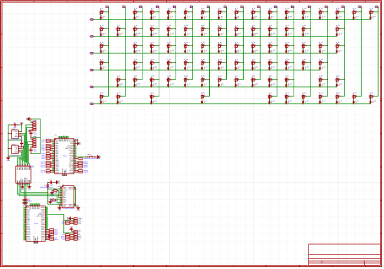
I clicked the update board button and deselected the things that were already there (the base keyboard), and I moved some things around and have this:
While looking at the connectors on the dislays I found this helpful review that I wanted to save for later
This TFT display looks great. I was able to very easily get it working with an Arduino Nano using some of the readily available Adafruit libraries. The only part that’s not well documented is that __SCL (also called SCK) connects to D13, and SDA (also called MOSI) on D11 for the SPI hardware interface pins (on a Nano). Don’t confuse it with similarly/identically named I2C pins on A4 & A5 – this display uses an SPI connection, not I2C. The fact that the silkscreen on the board is confusingly labeled withSDAandSCLcould easily make you think it is I2C, which it's not.__ It is bright and crisp, and I would gladly recommend it. You do need to solder the included header pins on yourself though. 5 stars.
Wow, that formatting looks really weird. hehehehehehehehehe
The deadline to submit if you want to go to highway is over, but I couldn't anyway, and just want a new keyboard.
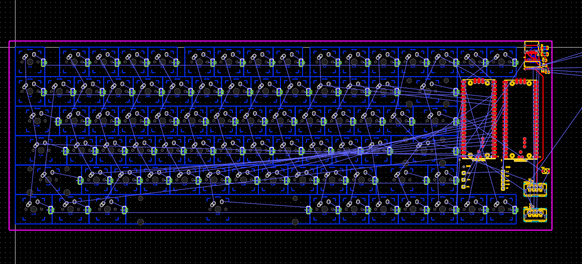
Ok, so now for the board. I decided to do 18mil traces which I think is ok, but for the USB-C connector i need some smaller ones. Overall it was pretty easy. The software (EasyEDA) automatically tells you what you need to connect so you just have to place the components and draw the lines, which I found fun because you have to switch to the back and stuff. Anyway, here it is.
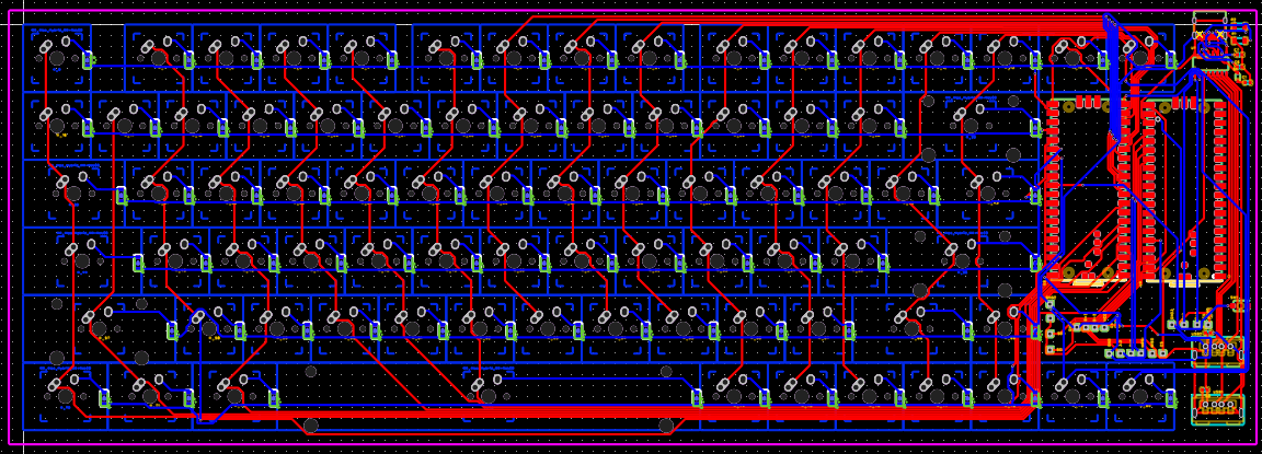
For some reason, the key outlines are like the same color as the traces on the bottom, but whatever. I'm pretty happy with how it turned out, but somehow I forgot to check what the key connection type is. I had intended to use Kalih hot swappable, but it seems to be for solder on MX or ALPS style switches. I think it's fine, because I'm not really going to be changing these out or anything, so I'm not going to bother re-doing all of that. One thing I hadn't anticipated is that you need the diodes on the back of the PCB, and it costs way more to get assembly on both sides, so I'll hand solder those, which should be possible because its is a SOD-123
footprint or something which is sort of big. I will, however be using JLCPCB to assemble one side because I don't have the resources to do SMD soldering. The Pi Picos will have to be hand soldered by me though, because they cost like $20 to do with JLC. In total, it looks like the PCB will be around $50+shipping from JLCPCB which seems reasonable to me. I accidentally deleted the item, so I have to redo it :(. Funnily enough, you have to buy 5 or more PCB, which seems wasteful, but I think its still the best value. Now that I'm checking again the shipping is $38 which is crazy! I'm trying to see if there's any cheaper option, but I don't know, maybe I'll just have to pay it. PCBway is still much more expensive.
3h
July 28
ugh its time, and i'm on vacation. I shouldn't have put it off this much. I am putting it all into cad and it going well. I need to make a case. I was going to have a plate that all the switches slot into, but I realized that it isn't neccesary because I am soldering the switches directly on, and I think it will look cool. I did some more stuff too, like screen mounts. I locked in and finished the CAD, its simple, but should be great
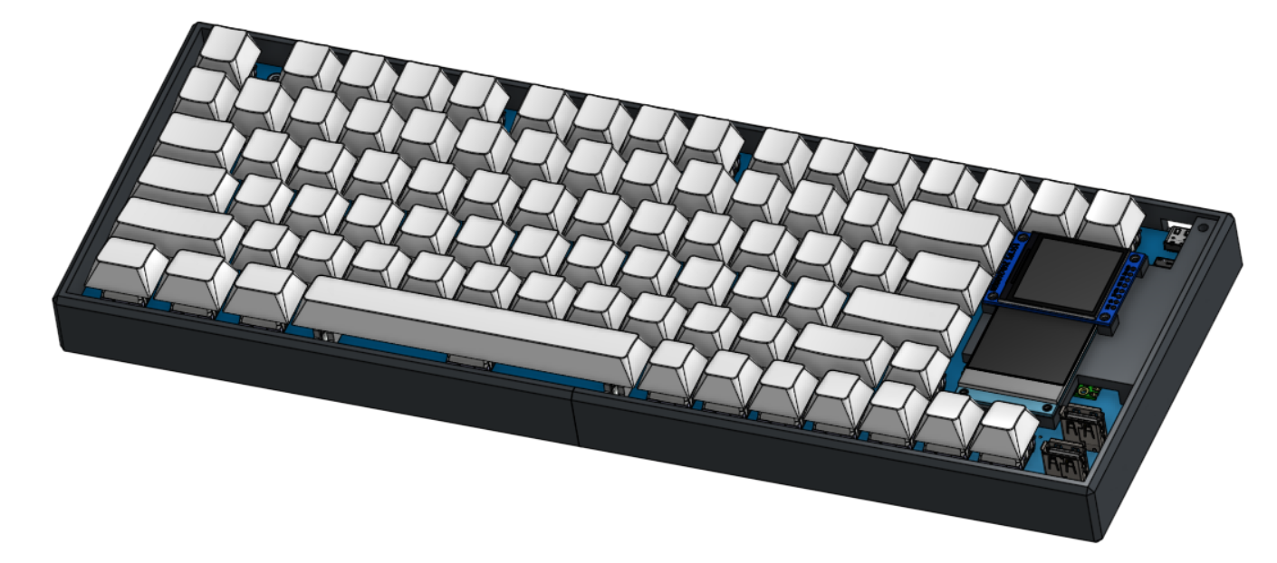
I generated the firmware from the kbfirmware.com firmware generator, but i cant test it yet. The software is hard to finish so far too, so a lot is unfinished.
Overall, I am happy that I was able to finish this in time, even though its not polished.
3h