
Total Time spent: 37 hours
5/24/2025 Log 1 Deciding a Gantry
Some of the main things I want to keep in mind while deciding a gantry is the cost and the size of the gantry, who wants to play chess on a 5 feet x 5 feet chessboard? Before deciding a gantry I wanted to lay out what were the bare minimum requirements my gantry should be able to achieve.
The gantry should:*
- Have high precision ( chess pieces not colliding on each other )
- Be robust, a chessboard is something that would have belts, motors, pulleys and etc moving all the time, it needs be able to not wear out too soon.
- Strong enough to support the weight of the electromagnet mechanism
+ High repeatability (be able to return to the same position multiple times
Note: Precision and repeatability do not need to be on the level of something like a 3D printer for a project such as this. Tolerances can be higher for this gantry as compared to a gantry needed for a 3D printer.
With this information I researched multiple different types of gantries and I landed on the coreXY. A popular and common gantry used in all sorts of projects including 3D printers. Motor control is simple with 2 motors controlling the movement of the gantry, horizontal movement is achieved from both motors spinning in the same direction, vertical by two opposite direction and diagnal movement is done by spinning only one motor.
A corexy gantry is composed of at least 4 pulleys, 2 motors, 3 linear rods ( or guides ) with 2 belts. After picking some choosing some components I designed a implementation of the CoreXy mechanism. I settled on 2 Nema 17 motors and linear rods as my main componenets. I designed 3d printed mounts and pulleys to connect the parts but the implementation had a problem, the gantry was too big, with the COREXY's strengths of precision and speed was the issue the space needed to accomodate such a large design, my current implementation was already over 600mm width.
After researching different smaller implementations I landed on T-Bot. T-bot is'nt the most common design and you wont see it in designs such as 3D printers because its not necessarily precise or fast enough for a 3D printer but it should work fine for a chessboard. Next session im going to start designing a H-Bot implementation Time Spent: 4 hours
5/26/2025 - 5/29/2025 Log 2 Designing my Gantry
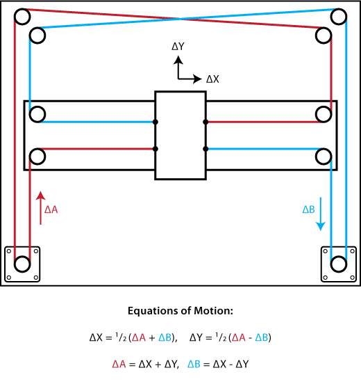
A T-Bot gantry is really a fork of the coreXY and thus the same principles apply, the belts controlling X and Y direction must be pararell. The design of a T-bot gantry is pretty self explanatory, it looks like a T. The gantry would have 2 linear guides, 2 Nema 17 motors, 8 pulleys and 1 belt. The assembly of this gantry would be more effecient and cheaper since we traded the extra guide and belt for 4 more pulleys. To pick which linear guides I wanted I looked at the specifications and differences between the different MGN## rails. A rail such as MGN12 would be a low profile rail which would handle less load compared to a HGR12. I picked 2 MGN12 Rails which were each 450mm. . The holes on the rail are too far spaced apart to just be directly connected so I made a 3d printed adapter to connect the two rails.
Now, the hard part is actually making the full gantry with the other parts ( belts, pulleys, motors etc ). I made a wood board frame for the components to be placed on top with holes spaced 25mm apart. The first thing I needed was pieces to connect the linear rails with the wooden board. I designed 3 pieces for the two ends of the rail and the center. . My vision for the implementation of the T-Bot gantry would be this, the red pulleys are idler pulleys and the blue ones being controlled by the motor. My drawing skills arent the best but it gives a general idea of the layout of the gantry, note the belts in the actual design would be pararal or else the tension would not be distributed evenly. I decided on small GT2 pulleys and some slightly bigger ones for the ones attached to the motor. I designed a motor mount and pulley mounts in order to hold the moving and idler pulleys. By convention NEMA 17 motors have the same X-Y dimensions so designing a motor mount was easier than I thought. I also had to design a a additional pulley mount to be connected to the guide rails. The biggest thing with the designing of these componenets are the positioning of the pulleys, the belts must be parallel.
This is not my sketch but its good for illustrating that even the belt thickness should be taken in account in this case im using a standard 6mm timing belt. After designing all my compoenents and placing them into a assembly I started making a belt but I constantly ran into issues of my belts not being parallel; sometimes a a pulley would be 2 mm displaced from another pulley, or sometimes I didnt take into account belt thickness but after trial and error I ended up with a parallel design
... actually I failed to notice the belts were intersecting through the linear guides. But it was'nt a hard fix and I adjusted all my pulleys a few milimeters higher in order to stop the clipping. I still had a few minor issues in my model, most notably different mates that were not fully defined but after fixing all the errors (I hope) I ended up with a finished product.
. I still have a little bit of work left to do on some of the models like the pulley mount but the main design is pretty much done. It took me a span of 2-3 days to design the gantry as I ran into lots of different types of issues I never encountered before but some helpful websites that helped me were
basic philoshpy and some common pitfalls when designing a gantry
Time spent: 9 Hours
6/4/2025 Log 3 Making a BOM
Since parts are accumulating fast and I don't want to lose track of parts I decided to make a BOM with all my parts im currently using. I split my BOM into 4 main parts, Electronics, Hardware, Raw materials and Misc. I decided to also section my BOM off with the type of componenent. A description of it and why I need it, a limk to the part and price by quanitity, quanity and the total price. Because most of my parts are sourced from the same types of manafacturers I added a columm with common manafacturers and totalled up my parts cost with them to save on shipping. Heres a snippet of the general template of the BOM .
Since my chessboard is 490mm x 490mm, instead of having a pcb of that size since it would cost alot I decided to split it up into a 100x400mm pcb, the reason for this is I would be getting 5 boards anyways and now I can use 4 of them saving more money. One thing to note is I did 100x400 instead of 100x500 since the extra 90mm is just the space outside the chess squares.
I attached a link of my bom here.
Time spent 1 hour
6/4/2025 Log 4 Hall sensor and Magnet Work
One of the most important parts of this project is accurate piece detection. There were 2 main implementations I could have done, magnets under each chess pieces with a matrix of reed switches or a hall sensor implementation. I decided to continue with a hall sensor implementation because unlike reed switches they will turn on and off instantly when my piece is removed. Reed switches suffer from ghosting issues where the switch might not close even after the magnets been removed. The type of hall sensor and how many I use is based on the magnet under each chess piece. Any typical N35 Magnet gives around 3000-4000 Gauss of magnetism but the strength of the magnet decreases exponentially, somewhat like a inverse cube. At just a distance of ~25mm the strength can decrease around 97%, from 2000 gauss to 60 gauss. One thing you might be wondering is where did I get the number 2000 from? Well in theory you would expectequal magnectic strength from all sides but a concept called flux leakage exists, the more 'uneven' a magnet is the more gauss can escape into different directions. This graph is a good representation for the rapid decrease in power over distance. The magnet in the picture is the same as the magnet im currently deciding to use for my chess pieces, a N35 magnet with diameter of 0.7 in and a thickness of 3mm. Some potential issues you might be thinking of is maybe the magnets field overlapping into another square and giving a false positive but because of the rapid loss in magnestism ontop of the fact that the hall sensor will be below a 3mm arylic I dont see that happening. A hall sensor I was researching was the KTH-1601, it has 3 different models in the package a throughole componenet and 2 SMD componenets also with 3 different sensitivity options, 22 Gs Vs 33 Gs Vs 46 Gs. At minimum I would need 64 hall sensors (one for each square) but I might need multiple sensors per square if I run into issues of overlapping but thats a issue which can only reliably be tested once the parts arrive. Due to the large amounts of sensors im using SMD componenets and 46Gs version to reduce issues of overlapping, at a distance of 3mm the gauss is still well over 46 meaning it will still be able to detect.
According to the manafactur datasheet (link here) the sensor is a binary sensor able to detect both south and north pole using a Schmitt trigger to prevent help with flucating values. Since im having 4 pcbs each 100mm by 400mm that means each pcb can encampass 16 sensors, to make wiring easier im going to use 16:1 multiplexer meaning only 1 muliplexer per pcb and I would only need to use 4 pins on my microcontroller.
Time spent 4 hours
*6/7/2025 Log 5 PCB for Hall sensor sheet *
My current electrical setup for the chessboard will be 4 pcb sheets (100mm x 400m) with 16 hall sensors, a 16:1 multiplexer and a ribon cable header pins, I will also have a additonal pcb with a microcontroller (have not decided one yet) power regulator and etc to act as the master pcb. My main pcb will connect to my 4 pcb sheets as well as the electro-magnet and 2x nema 16 motors. Im going to first design my pcb sheet since I have already figured out the parts for that. KICAD does not have a symbol nor footprint for the KTH-1601 hall sensor so I learned how to design a simplesymbol (albeit it does not look the best) with the 3 pins needed.
The datasheet for the KTH-1601 recommend a 1 microfared capicitor near the supply pin in order to reduce noise so I also placed a capacitor near the hall sensor. The general logic of the board is I will have the board powered by the
master board
and because of that Im going to have a 8 pin ribbon connect from the master board to the pcb sheet. The pins are needed for power, ground, data from the mux, and 4 pins are needed for controlling the multiplexer which leaves 1 pin as empty. Thats the finished schematic I have with all the parts I need for the pcb hall array sheet. Since the KTH-1601 also does'nt have a footprint I designed a simple SMD footprint. I'm deciding to use mainly smd components because the hall sensors and capacitors are over 128 pieces combined and soldering them from hand would take forever, to solder it im going to use a stencil and a hotplate. I spaced all my hall sensors 50mm apart from each other and 25mm away from the edge of the board, I also placed the capaicator close to the hall sensor in order to be more effective.
All my boards are connected by ribbon wires so I added a 8 pin header on the side of the board and on the bottom layer, I placed it on the bottom layer since its thick and it might have been harder to install the pcb into the chessboard if it was on the top. I also placed the multiplexer in the middle. Since most my componenents were SMD I didnt really need the bottom layer so I turned the bottom layer into a VCC and ground plane. I used vias in order to convert from the top and bottom layer in order the access the ground/vcc plane, I saved some extra wiring from doing this too. To make wiring more effecient I also placed vias to switch from bottom and top layer to reduce the amount of traces near the multiplexer. With that, I finished my wiring of the board
Time spent: 5 hours
** 6/12/2025 Log 6 Code/Board logic **
Before I started working on my board further I wanted to make sure the general logic of the board is decided. What I mean by that is my main objective of the board is to able to play chess against the user as seamlessly as possible, the user should not be having to debug or go through the mistakes the bot may make. One thing I wanted to get figured out was the homing of the bot, if the chessboard starts at a random position it will mistakenly think of that position as (0,0) which will make it go out of bounds and place pieces in the wrong place. To fix it I could use encoders or sensors in order to go to true
0,0 but a easier approach would be just to use the sensorless homing feature present in the TMC2209 motor driver. Sensorless homing does exactly what it sounds, it can home the bot to the correct position without the use of external sensors, it does this by moving the gantry in small increments until it hits a physical hardstop and the motor starts stalling at which point the driver knows the position of the bot and it can send that information back to the MCU in order to go back to 0,0.  One thing to note is sensorless homing as well as some of the other advanced features provided by the TMC are only available through the UART protocol. Motor movement and direction are through the STEP and DIR pins and motor configuration through the UART pin.
Another major headache is figuring out motor movement, since my gantry does not have dedicated motors one for X movement and one for Y movement I need to be able to find a effective way of moving the robot from 1 square to another. Another thing is my gantry can not move in diagonals, I need a custom movement system. If I moved in diagnols pieces would collide with each other. I need to move in the edges of each square.
One thing to note is sensorless homing as well as some of the other advanced features provided by the TMC are only available through the UART protocol. Motor movement and direction are through the STEP and DIR pins and motor configuration through the UART pin.
Another major headache is figuring out motor movement, since my gantry does not have dedicated motors one for X movement and one for Y movement I need to be able to find a effective way of moving the robot from 1 square to another. Another thing is my gantry can not move in diagonals, I need a custom movement system. If I moved in diagnols pieces would collide with each other. I need to move in the edges of each square.
Researching different implementations of a movement system I found G-code to motor movement pretty much for example what klipper does. I would generate custom G-Code depending on the intital square and the end square in pythonn I would then feed that into a firmware called FluidNc a G-Code to motor movement application common in many CNC's. This approach would be similar to klipper in 3D printers but the reason I didn't use klipper is because its not supported on ESP32's and I would rather use a more light weight firmware rather than one packed with features that I would barely use. I'm going to work on the code once I finish manafacturing my actual board but I wanted to first get a sense of what I would need to code and if I needed any extra sensors on my board. Its better to research and find out now then make my board and realize then.
Time Spent: 4 Hours
** 6/13/2025 Log 7 Master Board **
Earlier I made 4 PCB sheets with hall sensors but to control them I need to make a master board. My master board would be what controls the whole board, it would have a ESP32 as the MCU, a 12 volt battery for the Electromagnet and the 2 motors, a buck converter (12V to 3.3V) for the ESP32 and the hall sensors, 2x TMC2209 motor drivers, 4x of 8 pin headers in order to connect to the other 4 boards and a transistor to turn the electro-magnet off and on. Many of these parts do not have footprints or schematics so I designed footprints and schematics for the buck converter the motor drivers and the esp32.
I started working on the schematic of the board but because im new to the UART protocol I looked into the datasheet and learned more about the correct implementation and the function of each pin on their datasheet. I learned that you should connect both your MCU's uart pins to the motor driver one and be using a resistor in order to allow for bidirectonal data, it allow allows the manafactur to only need 1 pin. One more thing I did was add a 100uF capacitor near ground and vcc since it would help with voltage spikes as motors are notirious for voltage spikes. I found a transistor that turns on and off with only a 3.3v and connected that to my electromagnet to act as a gate. I then added my buck converter in order to convert the voltage into something the MCU and hall sensors could use, to connect to the other 4 pcb sheets I added my header pins as well
For my layout I just arranged my components to fit within a 100x100 pcb and routed it.
Time Spent 4 Hours
6/14/2025 Log 8 Updating CAD and BOM**
I added lots of new parts since last time I worked on the CAD so I wanted to update it to be reflective of the changes. The first thing im going to design is a electromagnet holder in order to house the elctromagnet, it will be attached to the gantry through 2 counter sink screws
I also increased the size of the top panel of the chessboard in order to cover the entire 590mm by 590mm chessboard. I also added physical endstops to the pulleys to help with sensorless homing, I imported the electronic components onto the board such as the 4 hall sensor sheets and the master PCB, added a physicalo enclosure around the board and added screw holes to hold the enclosure together. I ran into some issues of parts not fitting and I had to move some parts in order to make space but in the end I ended up with a hopefully finished cad
Time spent 3 hours