QuestDeck
A writerDeck style Cyberdeck design specifically for TTRPGs
Total hours so far: 56
Day 1: 14th June 2025
Research Planning
I did some research on r/writerDeck to see some existing designs, their use and the types of software they use. I was particularly inspired by this design, which makes me want to make something foldable and compact so that it is portable.
I'm not sure how possible it is to make a keyboard that is easily foldable like that. Maybe scissor switches would work but I don't think they are possible for DIY, or even a membrane keyboard but it doesn't seem very plausible either. I also really like this design:
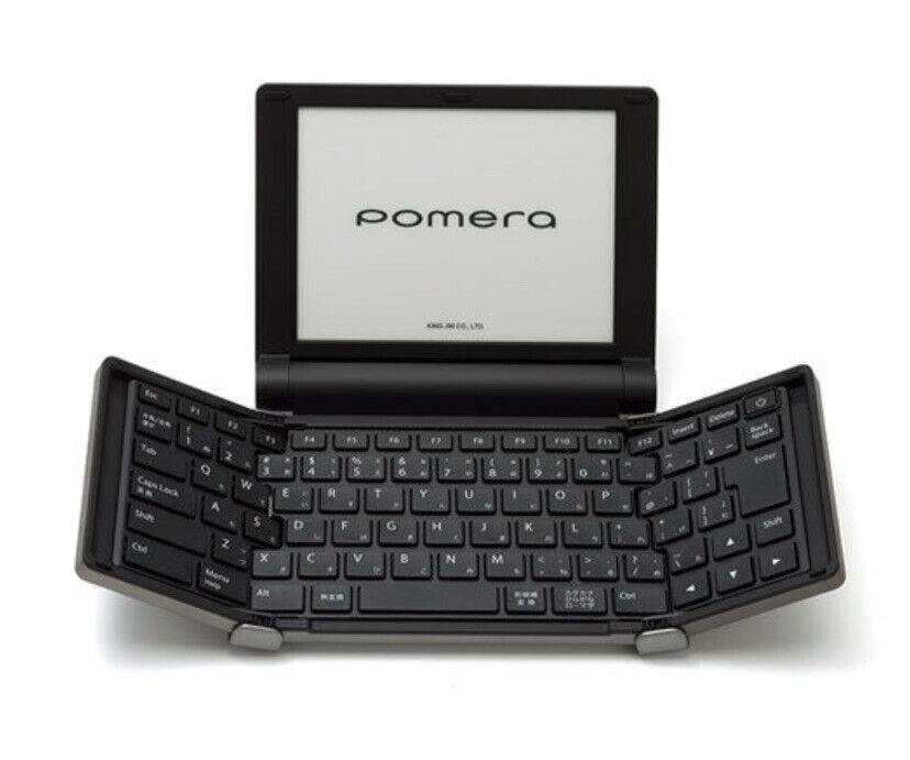
Both the designs I really like are from Pomera. I think I will try using Low Profile keyswitches and see if I can make a case that accomodates folding. The overall design will be a lot thicker but I still think it could be really cool.
Research: +3 hours
I also want to have a slide out screen at the bottom which will be a 'dice roller', so one of the keys will activate it, and you can choose how many sides it has and roll it. I will make it run off a Raspberry Pi Zero 2 W or Zero W, and then I will have the custom keyboard connected to a Adafruit KB2040 (RP2040) using its USB Breakout.
I drew a rough design based on these features:

I also drew a design of the keyboard folding mechanism made for a mechanical keyboard thickness:

I think I will use Kailh Choc V1 switches and then I could use custom MBK keycaps from FK Custom.
Research: +2 hours Planning: +1 hour
+6 hours
Time Spent on This Day: 6 hours
Research: 5 hours Planning: 1 hour
Day 2: 15th June 2025
Schematic PCB
I wanted to try and smash out the keyboard part of the schematic as I already have experience designing keyboard schematics so it shouldn't be too hard. First I decided where the keyboard would be split and what special keys (such as Roll for the dice roller) I would have for it. I used Keyboard Layout Editor to make the layout:

I then designed the schematic around this design. I named all the keys to make everythin easier to keep track of:

I decided to use the KB2040, an RP2040 based board, for my keyboard. This is because it has USB breakout meaning that I can pass the USB signal from the KB2040 to the Raspberry Pi through the PCB, rather than having to plug it in and manage those wires. This just helps with the size constraints of the project.
I will put the KB2040 on the 'Dice Roller Screen' PCB as there is not enough space on the keyboard. I can pass the row/column signals through an FPC cable from the keyboard to the KB2040. On that PCB there will also be a 128x32 OLED display which will display the dice rolling. I have also used this before in my Hackpad so it shouldn't be to hard.
I will have to use an IO Expander to handle all these signals as the KB2040 does not have enough pins. Again, I have used this before. Here is what the FPC to the 'Dice Roller Screen' PCB part looks like:

And the whole thing:

Next I will handle how the keyboards will be on separate PCBs. I can again use FPC cables to pass the signals to the centre PCB. Here is what that looks like:


Schematic: +4 hours
+ 4 hours
I decided to attempt the long process of putting all the keys in their correct spots with all the spacing for the PCB.
Because I decided to use Choc v1s there weren't good footprints in EasyEDA for the different size keys. I decided to instead use 1u footprints for all of them and manually calculate the spacings.
For the initial PCB placings I decided to just make it as one unified keyboard and then I can separate them after and add the board outlines for each. Here's what it looks like as the one part keyboard without the routing (ratlines hidden):

PCB: +4 hours
+ 4 hours
Time Spent on This Day: 8 hours
Schematic: 4 hours PCB: 4 hours
Day 3: 16th June 2025
PCB
I first did the routing for the keyboard as well as splitting it apart and adding board outlines.
I made sure that on each split both FPC sockets were at the same height to make sure the cables will be able to connect:

PCB: +3 hours
I then routed the 'Dice Roller Screen' PCB which also has an FPC cable. This FPC cable was harder to route as it is much bigger. I had to also make sure that it was lined up with the Centre Keyboard FPC above it. Here's what the 'Dice Roller Screen' PCB looks like as well as the corresponding FPC on the Centre Keyboard:


PCB: +1 hour
+4 hours
Time Spent on This Day: 4 hours
PCB: 4 hours
Day 4: 21th June 2025
Schematic PCB
I added the 'Top Screen' PCB to the schematic. The mainboard is the Raspberry Pi Zero 2 W and it is powered by a 2400mAh LiPo Battery. I am using a TP4056 for a charging module with USB-C, and also with a MT3608 boost module for the charging system. It is also connected to the rest of the PCBs through another FPC connector. Here is what that looks like in my schematic:

For the USB connection of the keyboard, I used the USB breakout on the KB2040 but on the RPi the USB breakout is on the underneath of the board. I don't think it is feasible to use the underneath of the board as it will be soldered to the PCB.
I have a makeshift solution that I just have to hope will work. I am going to use a USB breakout like this:

Plug it into the Pi and then run wires between the breakout and some pads I have put on the PCB. No idea if this will work but I suppose I will find out...
Schematic: +2 hours
I have wired it all up on the PCB and here's what it looks like:

PCB: +1 hour
+3 hours
Time Spent on This Day: 3 hours
Schematic: 2 hours PCB: 1 hour
Day 5: 22th June 2025
Research
I did a whole lot of research on custom MBK keycaps and here's what I've figured out:
For my keycaps, I have some interesting sizes, such as 4.75u. Although 2.25u, 1.75u, and 1.25u are not considered odd sizes, the place I was going to get the custom keycaps from, does not have them. They only have 1u, 1.5u and 2u.
I can no longer use FK Custom for my custom keycaps, and as they are the only place I can find that do custom MBK keycaps, I am going to have to find another solution. I've looked for similar style Choc v1 low profile custom options but can't seem to find any.
My first thought is to change to Choc V2 which have a Cherry MX stem, as then there are many more options for custom keycaps. I don't particularly want to do this as they are slightly bigger, and it also just wasn't really my original goal.
I have looked for other low profile switch options so that I can get keycaps. I looked at Kailh X switches which are basically more DIYable Scissor Switches.
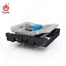
Although they have very mixed reviews about the longevity of the switch, and will also be hard to add as a footprint to my PCB. Although they seem super interesting so maybe I will try them out for another project. I also did research into maybe making a membrane keyboard as that gives the option for being super low profile. I pretty quickly realised this isn't really possible and it would be very hard to make, get produced, and very expensive.
So I guess it's back to the Choc V1s. I did some research into how to make my own custom keycaps with legends, but this involves materials and skills I don't have. But what if I just 3D print them?
I think this is what I'll do. I can use multicolour inlay on the top of the keycap (printing top down) to give the legends. This also means for the keys I have such as Roll, I can fully design what the legend will look like in Fusion.
I have found these keycaps which fit the vibe really well and are also flat on top making it much easier for the legends.
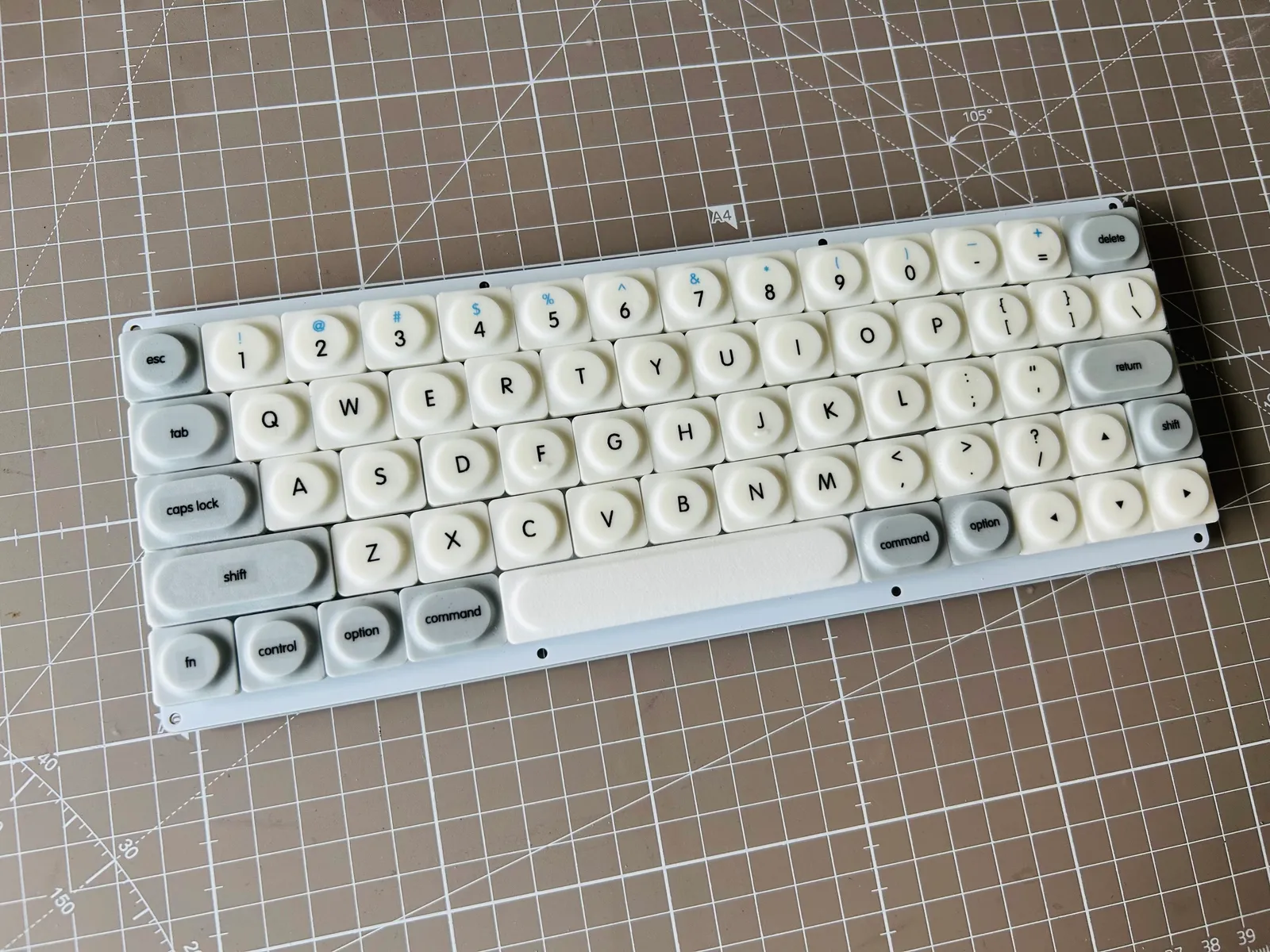
When I get to making the keycaps I can make the inlay legends in Fusion, which should not be too hard. But I'm not going to add them until later.
Research: +5 hours
+5 hours
Time Spent on This Day: 5 hours
Research: 5 hours
Day 6: 28th June 2025
CAD
I first exported the PCBs as .STEP files from EasyEDA and imported them into Fusion to start the case.
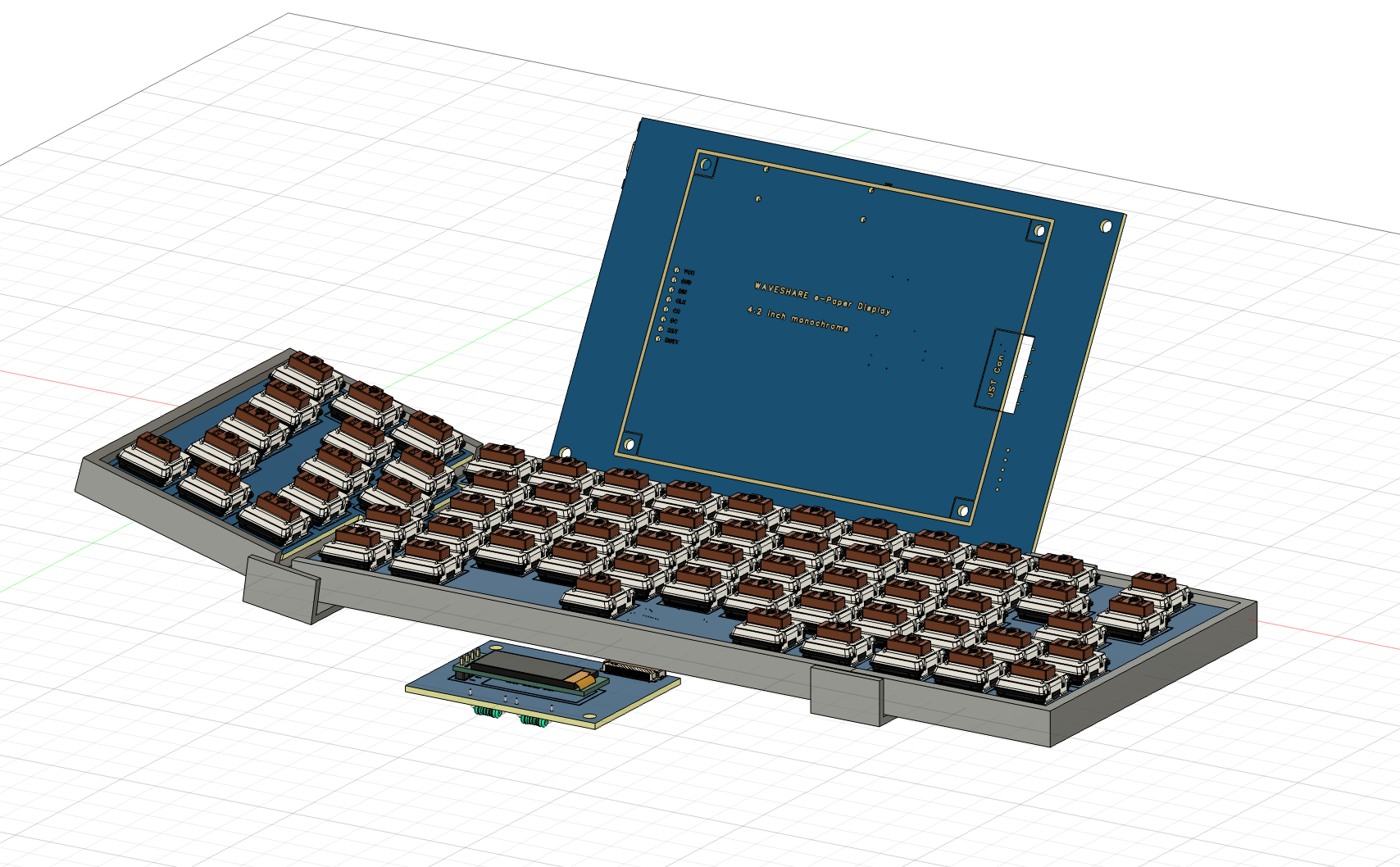
I started modelling the case based on the original designs I had and here's what that looks like:
CAD: +1 hour
I realised there are a few issues with this design:
First, I wanted the dice roller screen to slide out from under the keyboard, but with the height of the PCBs and the limited space, this will not be an option
Second, if I tried fold the keyboard using this design, it would just get stuck as there is not enough space allowed for the hinge motion.
I will leave issue 1 for later, but attempt to address issue 2 now. I widened the hinge that is there as well as making a slider path that will have a pin meaning that the keyboard can slide further out as it folds preventing it from getting stuck.
Here's what that looks like so far:
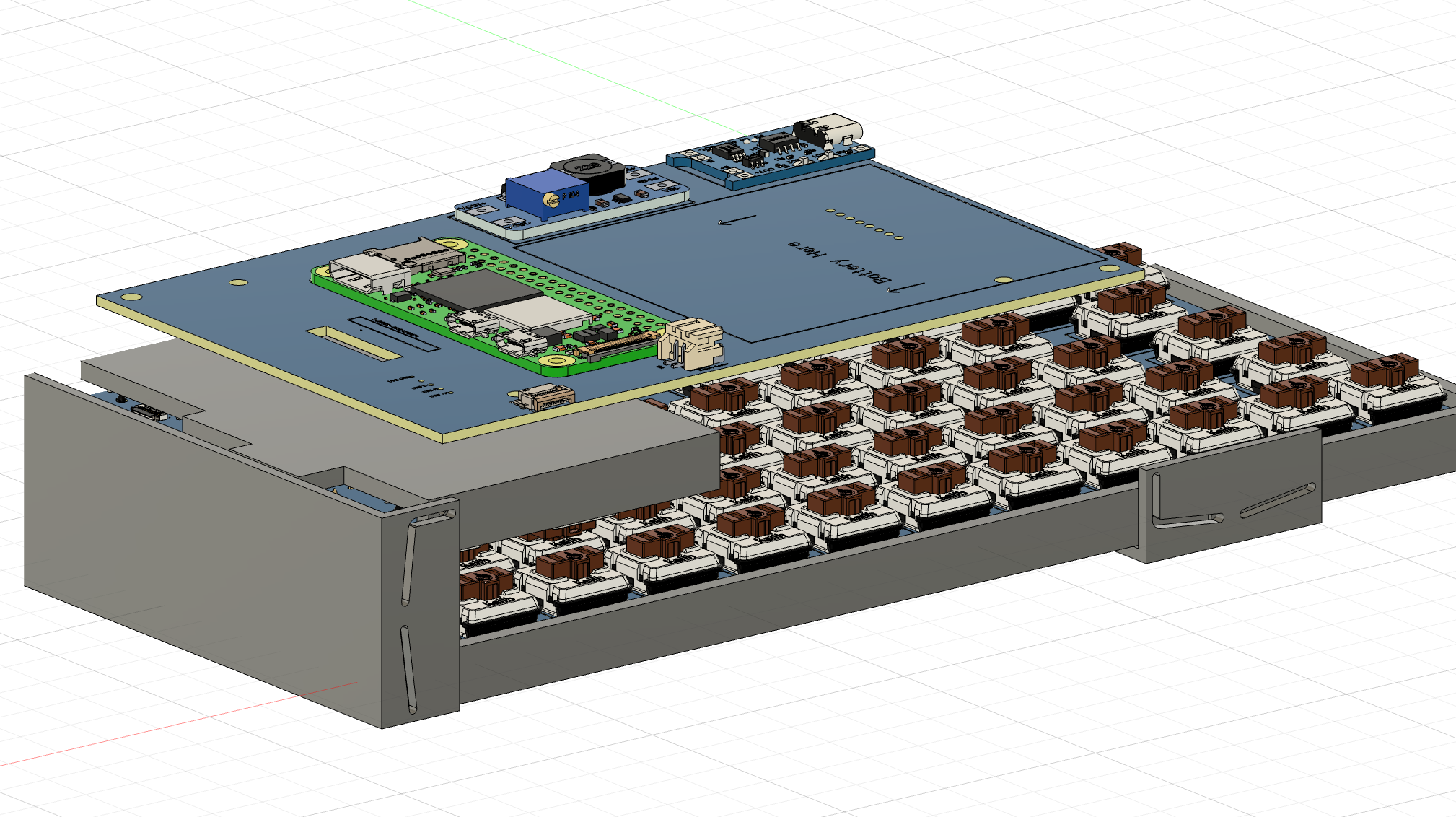
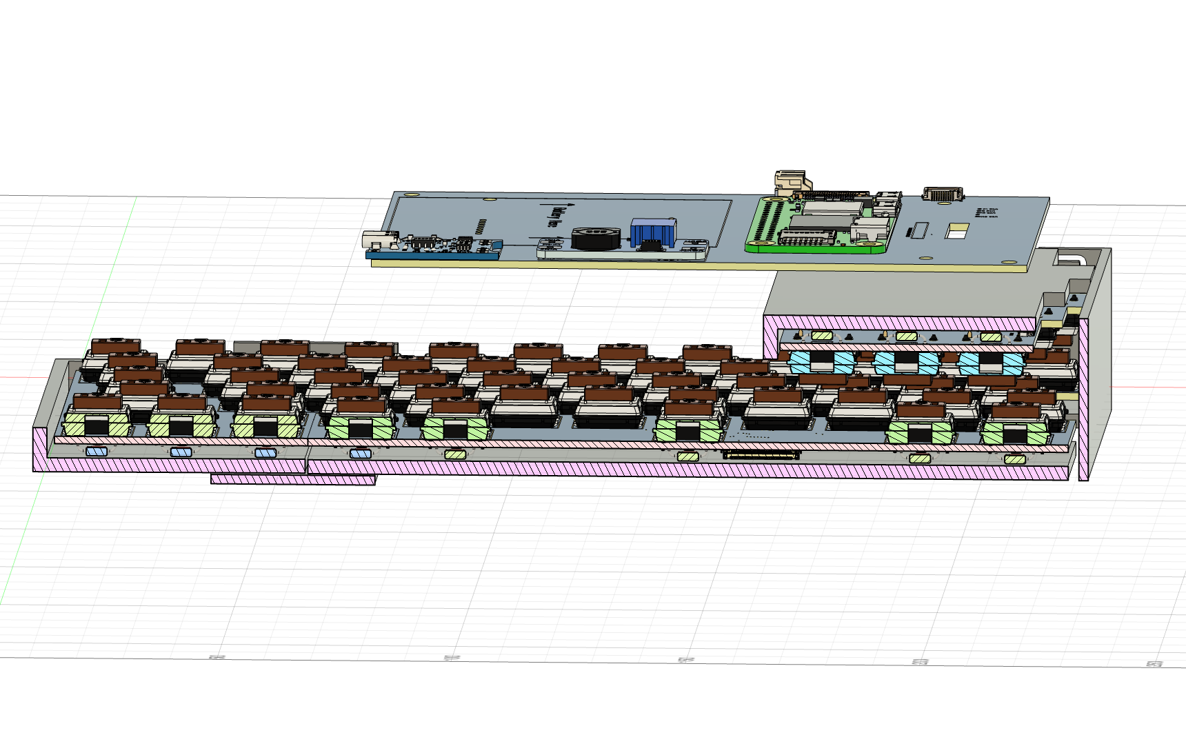
I'm pretty sure that should allow the keyboard to fold nicely... hopefully
CAD: +3 hours
+4 hours
Time Spent on This Day: 4 hours
CAD: 4 hours
Day 7: 29th June 2025
CAD
I next modelled the enclosure for the top screen to go in, that will hinge to the main body:
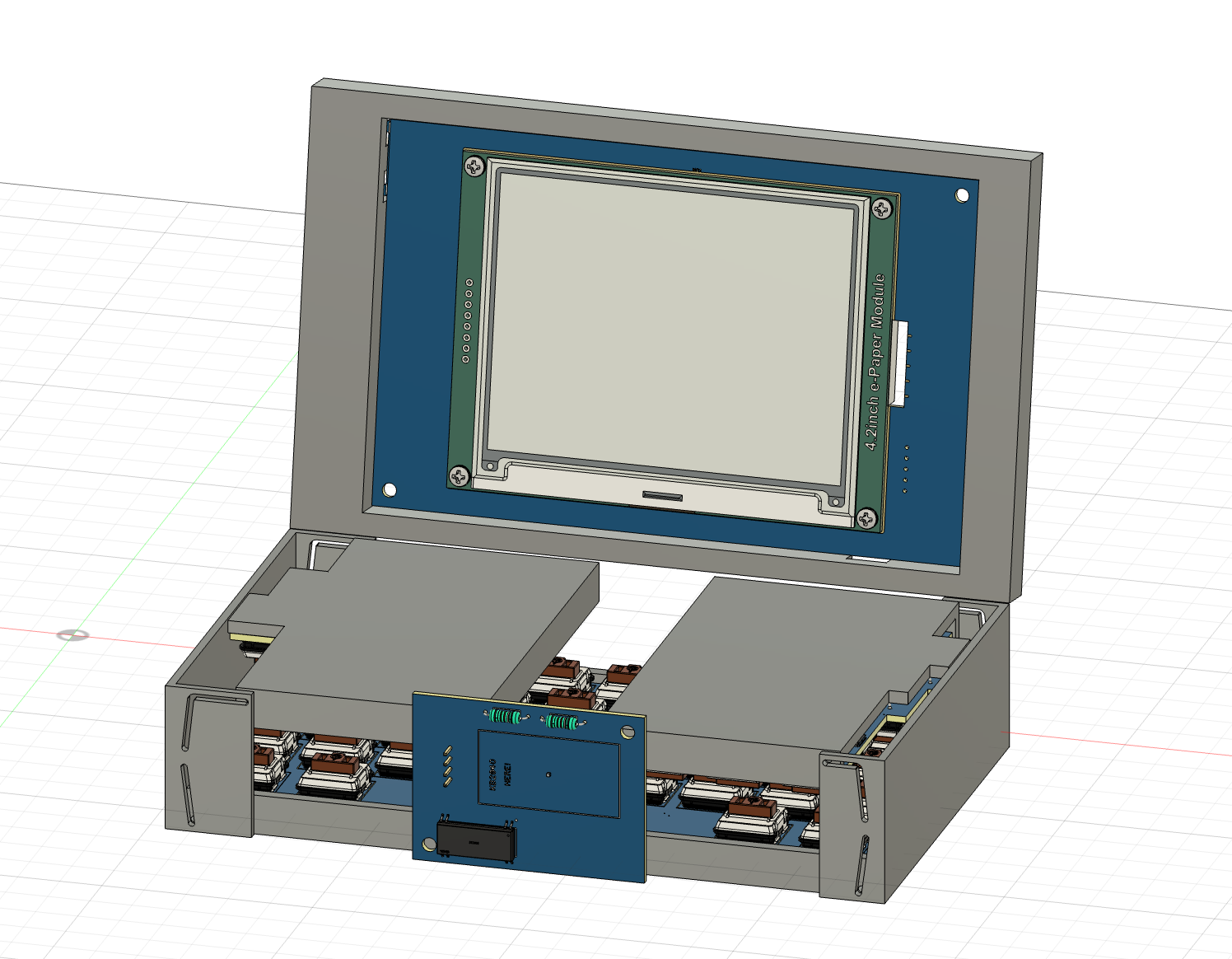
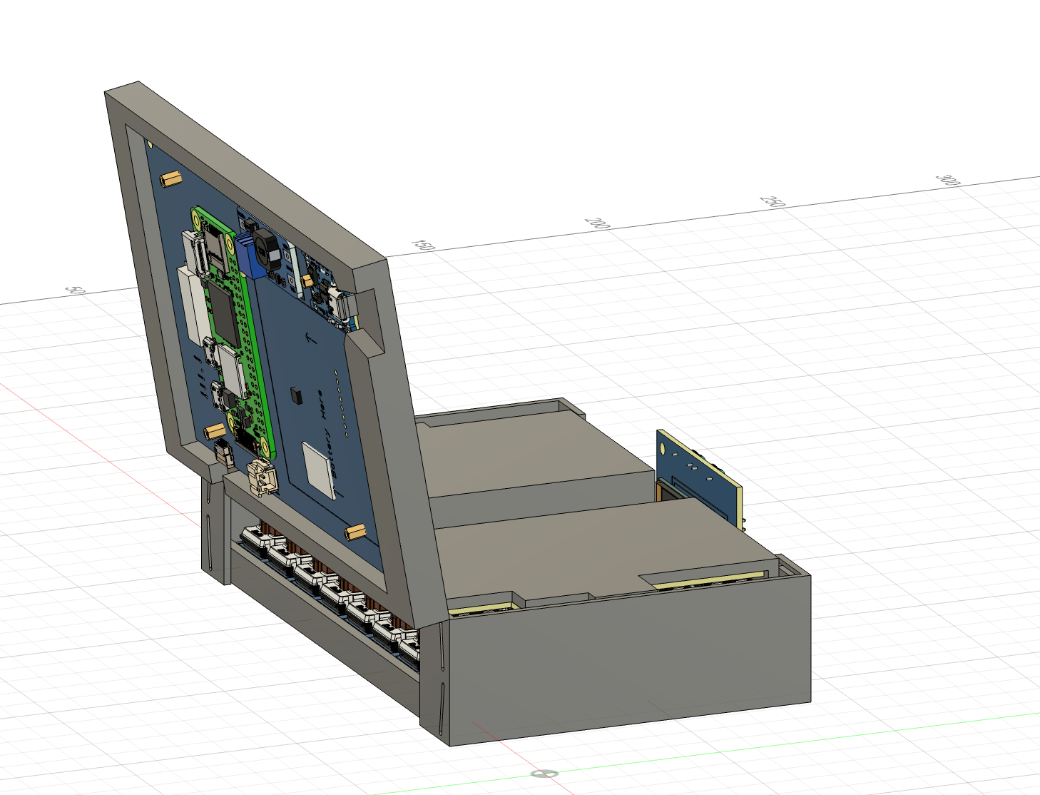
I have decided for the dice roller screen, instead of having in slide out, it will also hinge and sit against the body when closed (as shown in the image above).
CAD: +2 hours
+2 hours
Time Spent on This Day: 2 hours
CAD: 2 hours
Day 8: 30th June 2025
CAD
I first recloured everything in the CAD to make it more accurate to what I want it to look like:
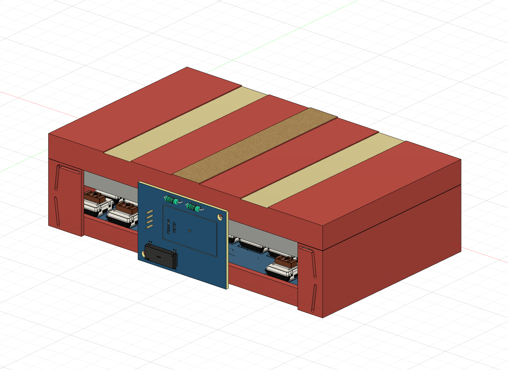
I then realised the the top screen can hinge from the spot it it hinging from; it is currently connected to the bottom of the left and right keyboards, but when the keyboard opens, it can't connect to there.
In order to fix that, I can add a spine and connect it to that. The spine can then connect to the bottom of the centre keyboard which will stay in the same position the whole time.
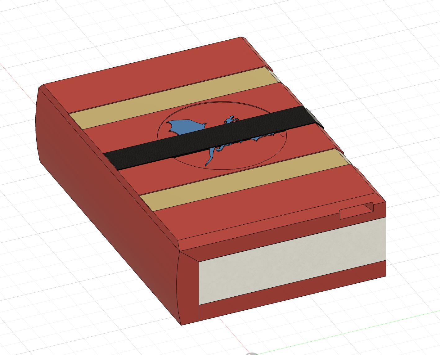
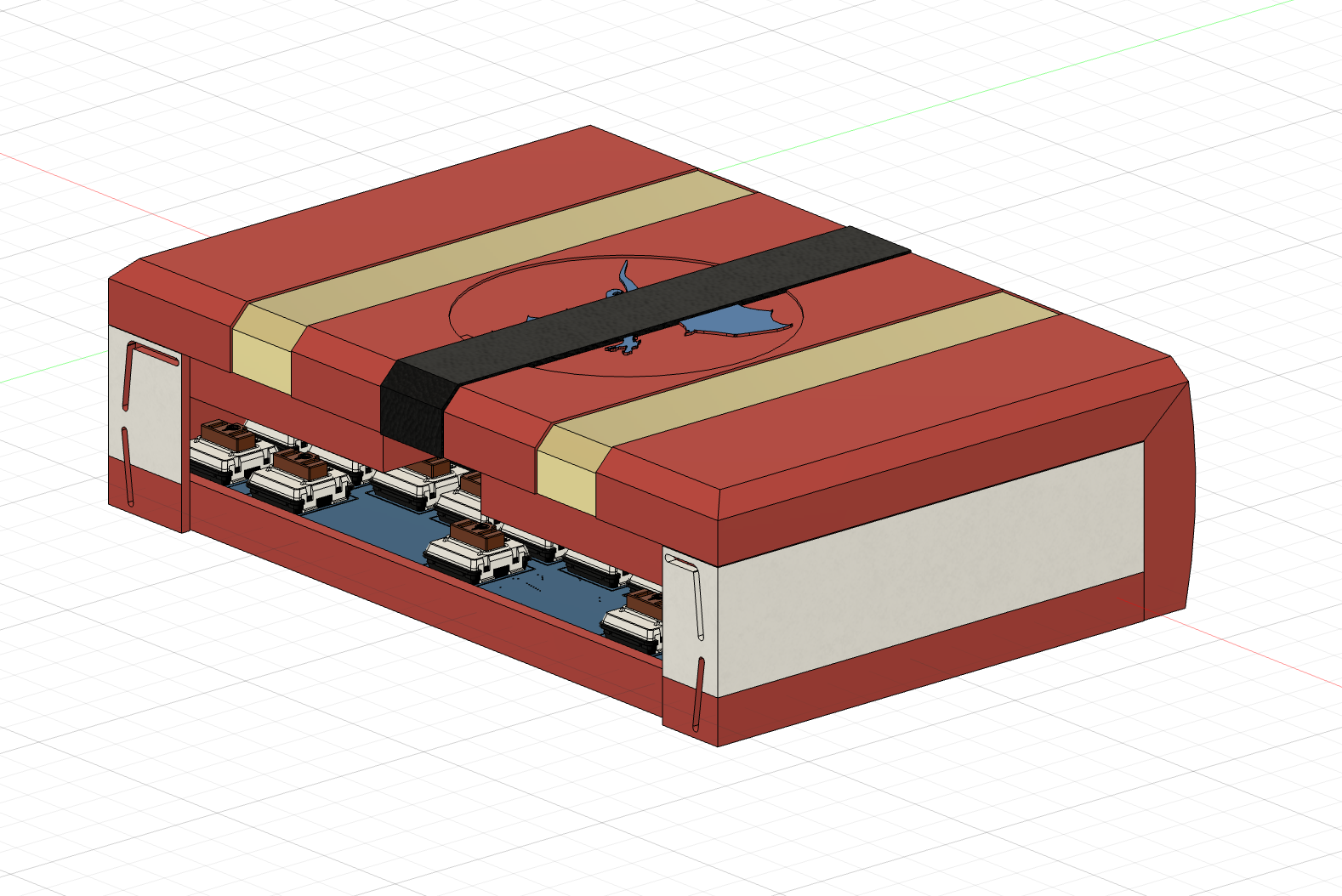
I also changed the design on the book cover and I think it looks pretty cool.
CAD: +3 hours
+3 hours
Time Spent on This Day: 3 hours
CAD: 3 hours
Day 9: 1st July 2025
CAD
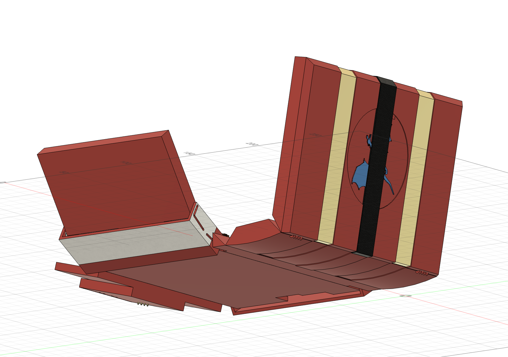
I blocked out a quick enclosure for the dice roller screen that will also hinge of the bottom of the centre keyboard:
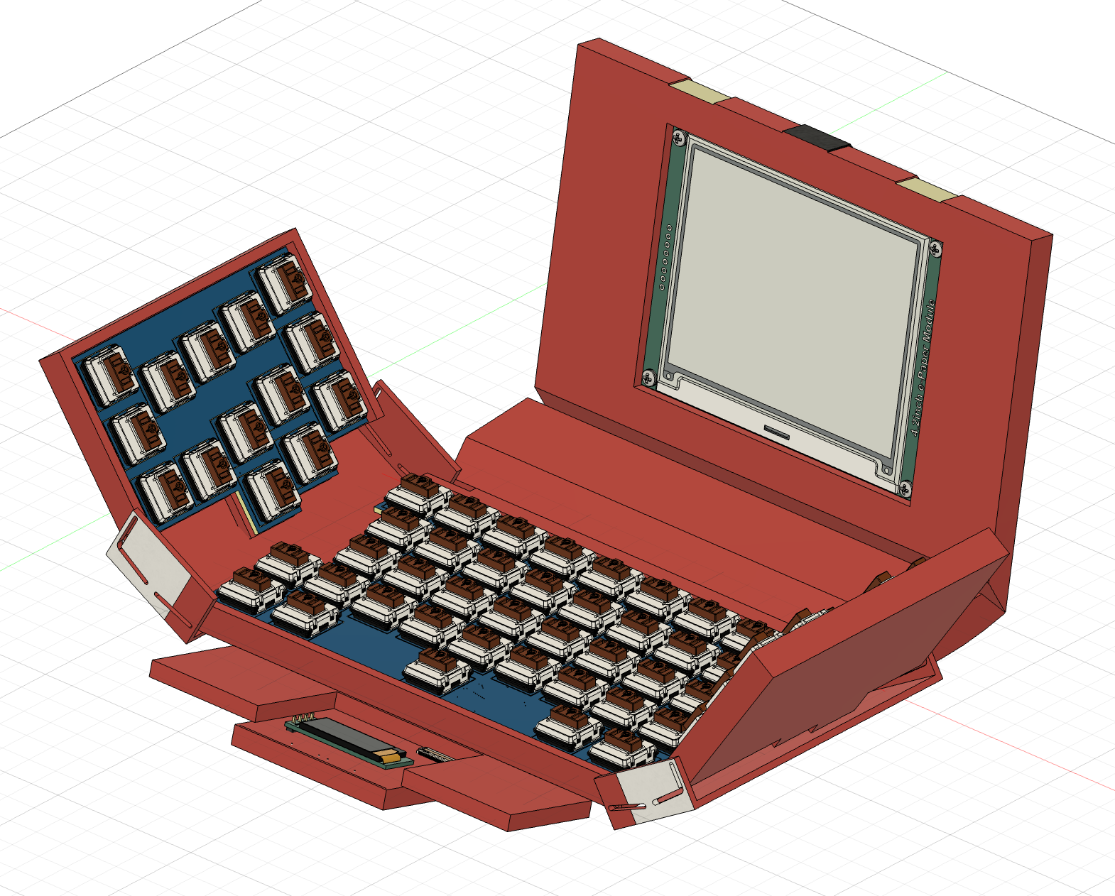
CAD: +3 hours
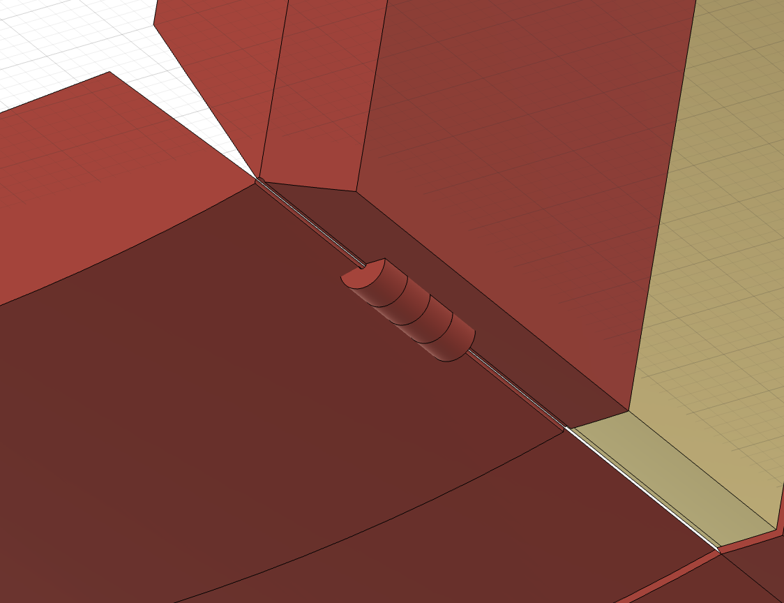
I then added little hinges on the spine that will have a metal rod go through the middle to hold the parts together and allow the to hinge:
CAD: +2 hours
+5 hours
Time Spent on This Day: 5 hours
CAD: 5 hours
Day 10: 2nd July 2025
CAD
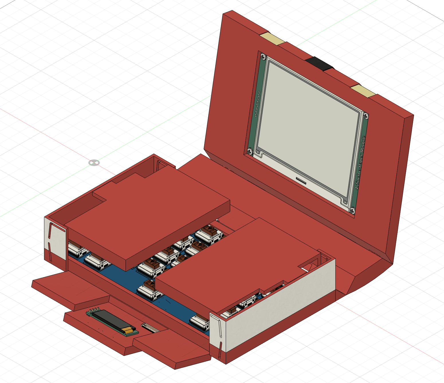
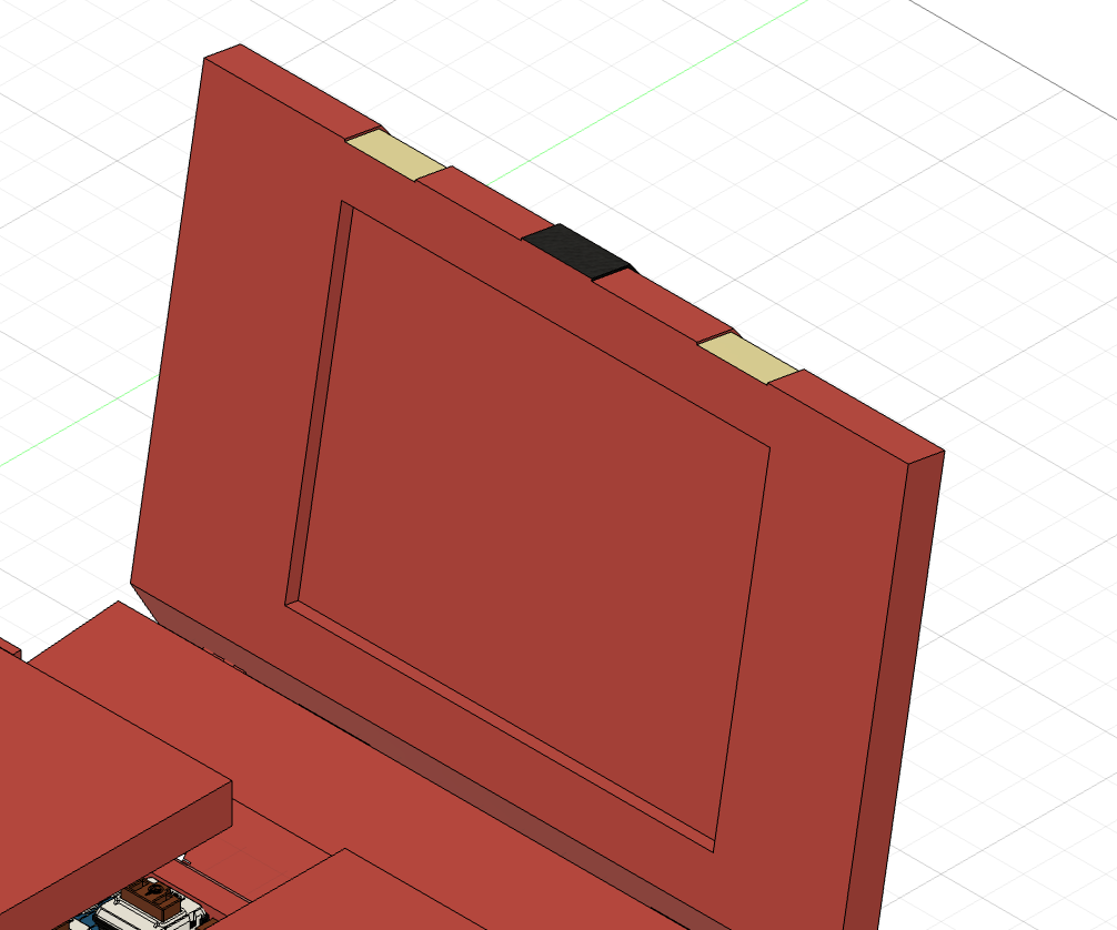
I remodelled the space for the top screen so that there is the right space for the screen and PCB:
CAD: +2 hours
I also remodelled the enclosure for the dice roller screen, so that it fits well between the keyboard hinges, and can be separated into 2 parts so that it can be put together:
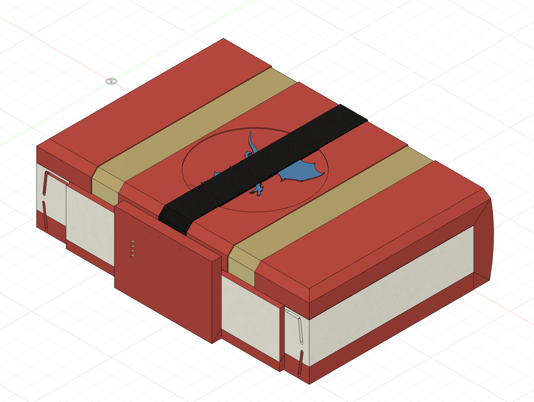
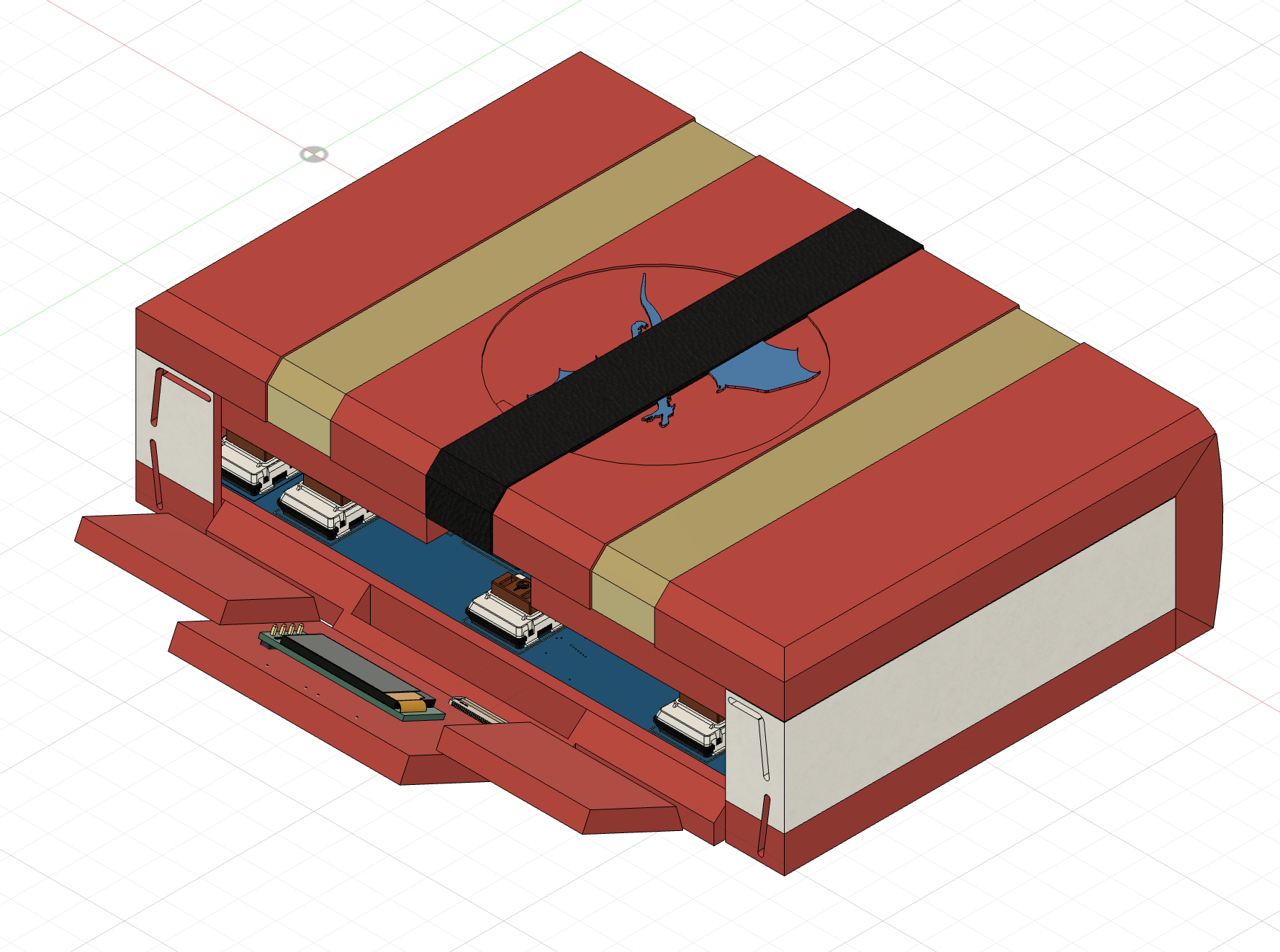
I then separated it into 2 parts that screw together and and mounting spots for the PCB. I added screw holes on tabs off the side so that it can connect as securely as possible.
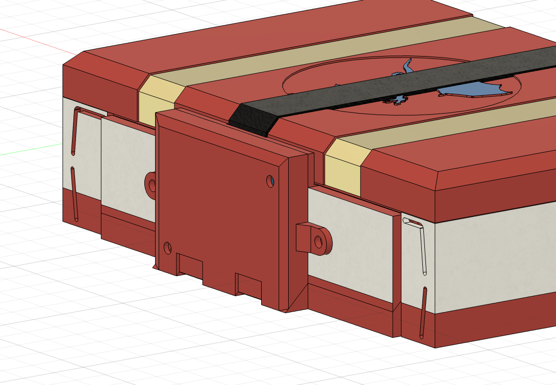
I also added a slot for the hinge to sit.
CAD: +3 hours
+5 hours
Time Spent on This Day: 5 hours
CAD: 5 hours
Day 11: 8th July 2025
CAD
I designed the dice roller screen to look like a lock on the book. I am going to print it in gold filament because I think that will look super cool. Here's what that looks like, and also what it would look like without the lock part on it:
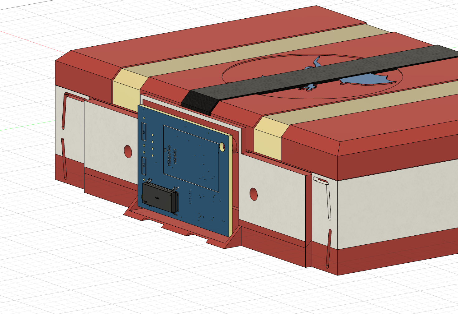
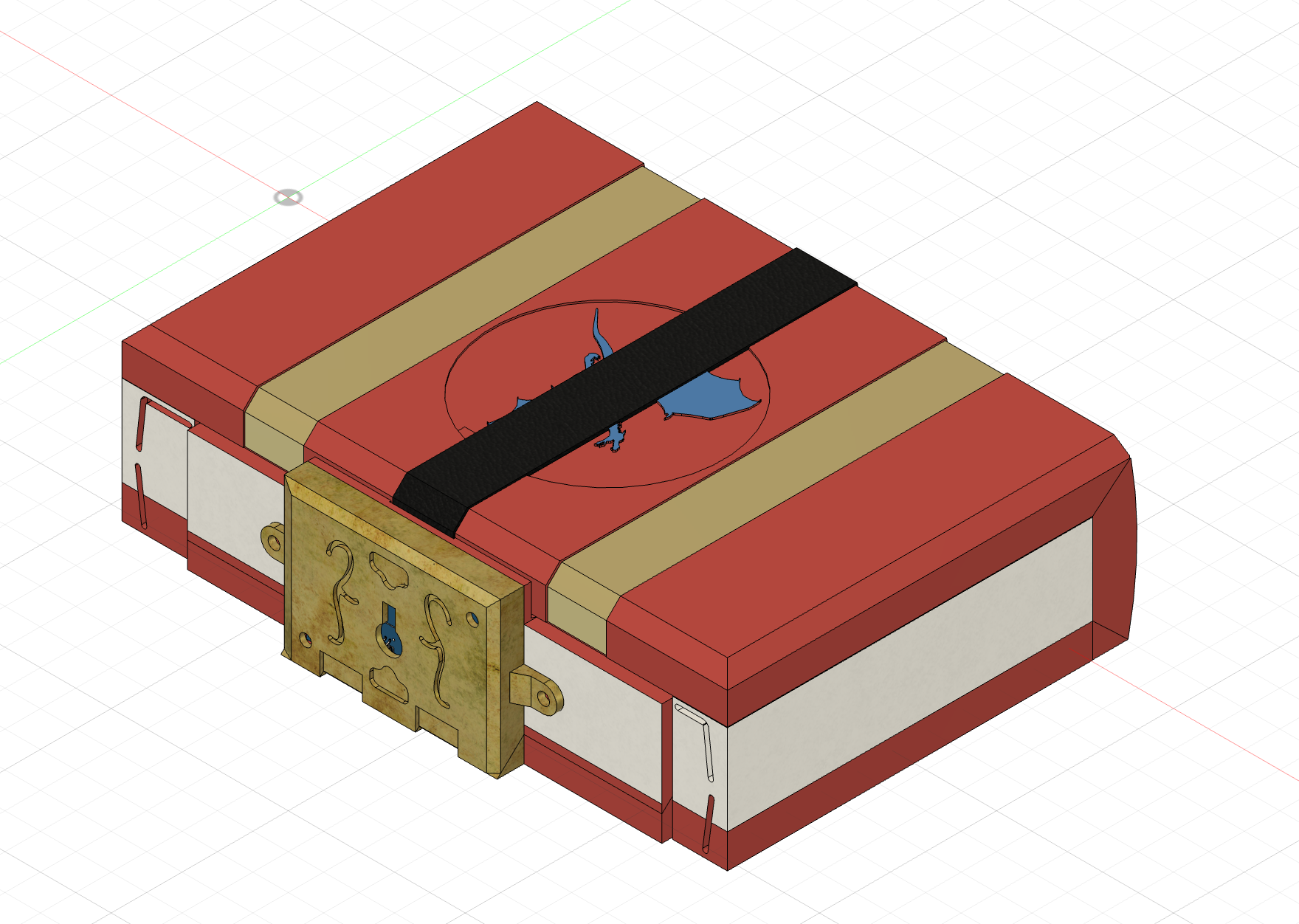
Here's what the full CAD model looks like so far:
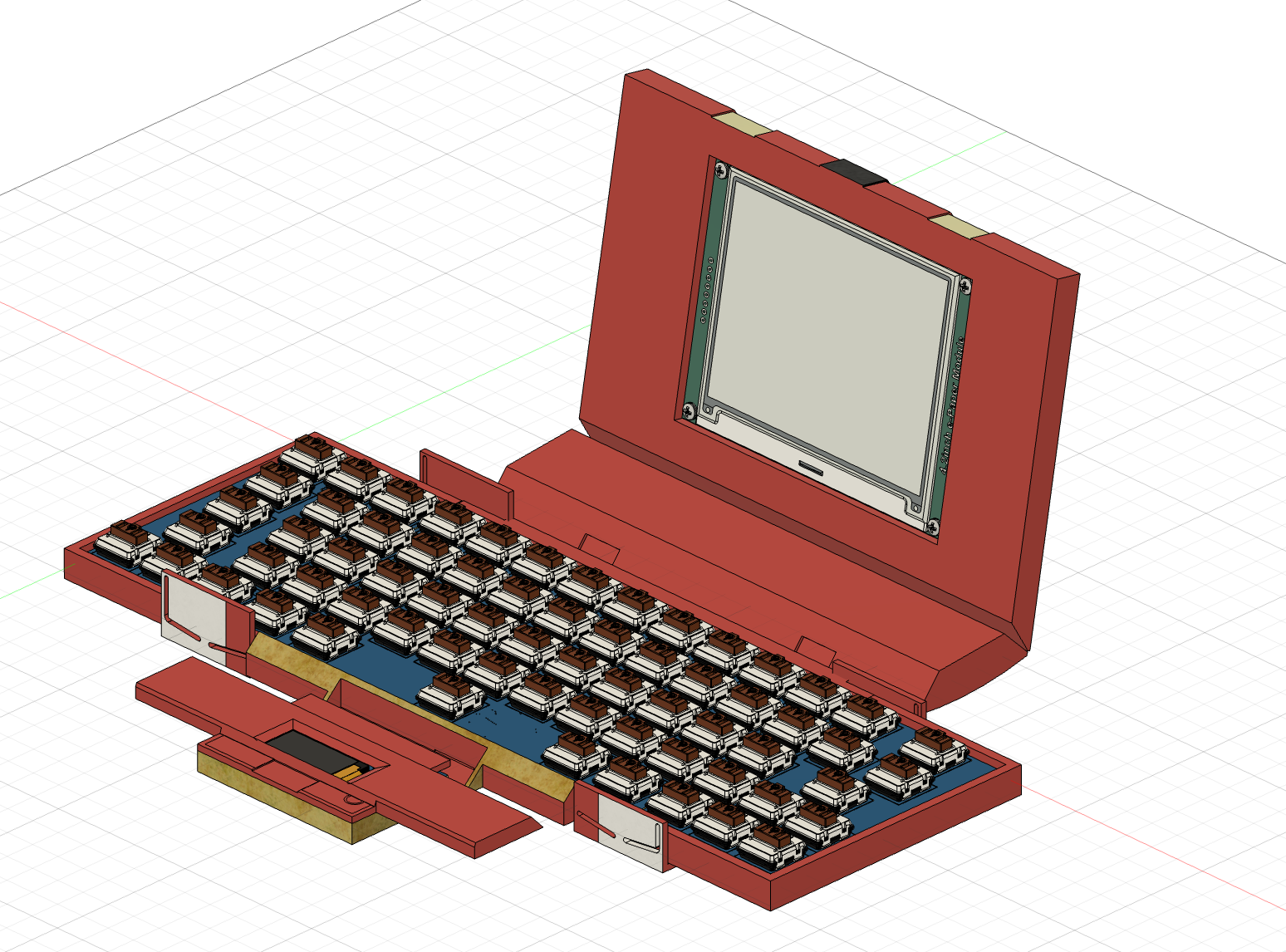
I'm so happy with how it's looking so far!!!
CAD: +2 hours
+2 hours
Time Spent on This Day: 2 hours
CAD: 2 hours
Day 12: 10th July 2025
CAD
As I already added the hinge slots to the dice roller screen, I also added them to the spine, as well as adding bigger hinges as I don't think the ones I had would be strong enough.
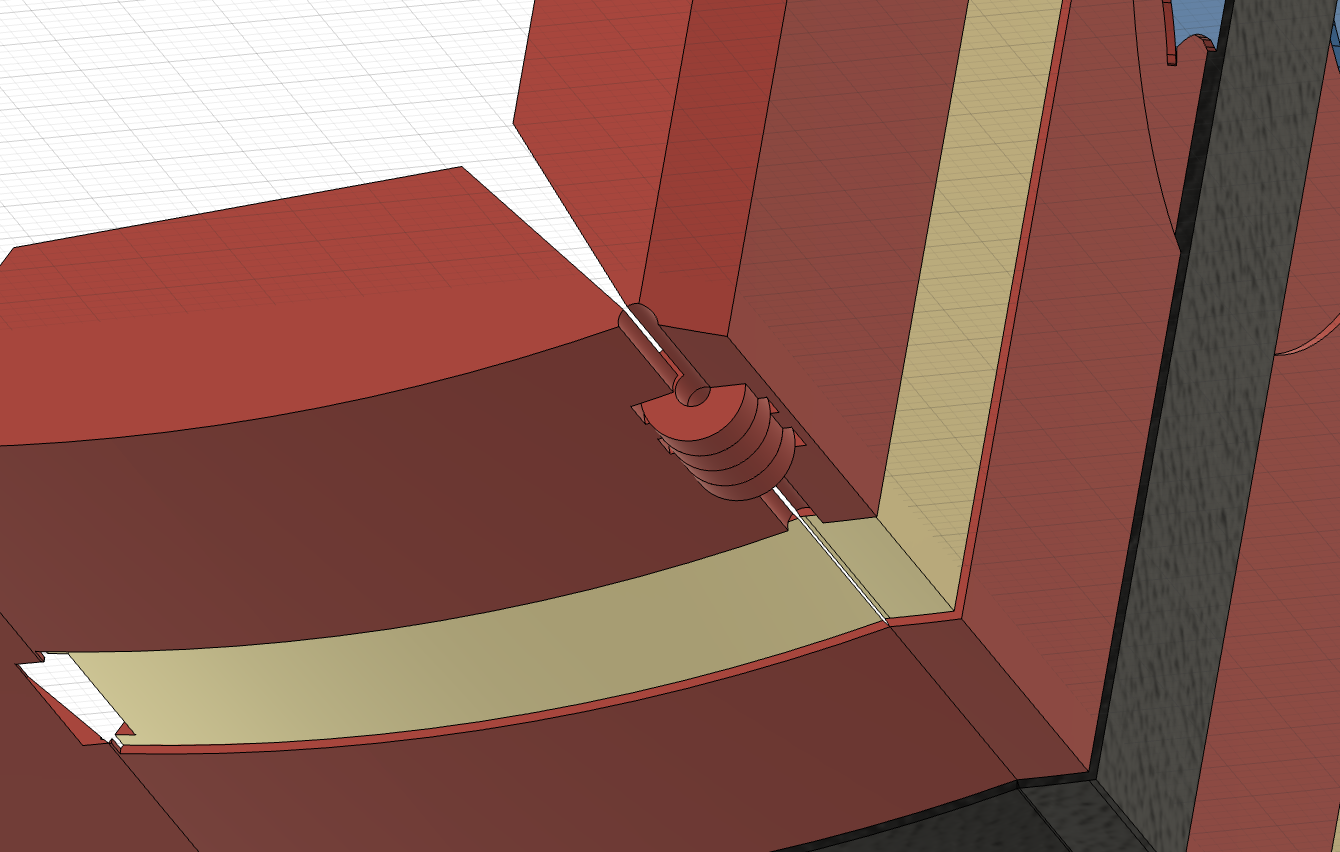
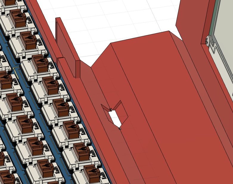
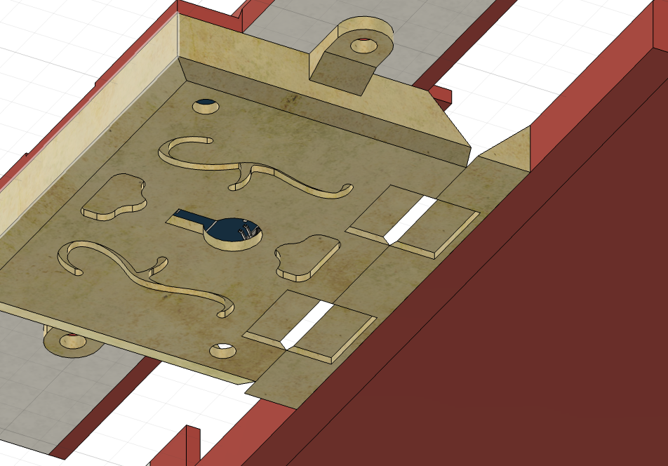
I think I will just glue the hinges in rather than screwing them as there is no info on the product of the hole size or location. If that doesn't work then I will measure the hinge when it arrives and add the holes based on that.
For some reason I had a lot of issues with changing the size of the integrated hinge, it kept messing up the timeline and changing everything else which was really annoying. I ended up getting it working but it took way longer than it should have.
CAD: +3 hours
+3 hours
Time Spent on This Day: 3 hours
CAD: 3 hours
Day 13: 19th July 2025
Firmware
I made a custom configuration for the keyboard using QMK. None of the configurator templates match my layout so I had to write the code myself.
I have written the firmware for the keys and added a spot for the macro for the 'roll' key. I want to configure the macro when I get the parts as I am having a really hard time figuring out the inputs without being able to test.
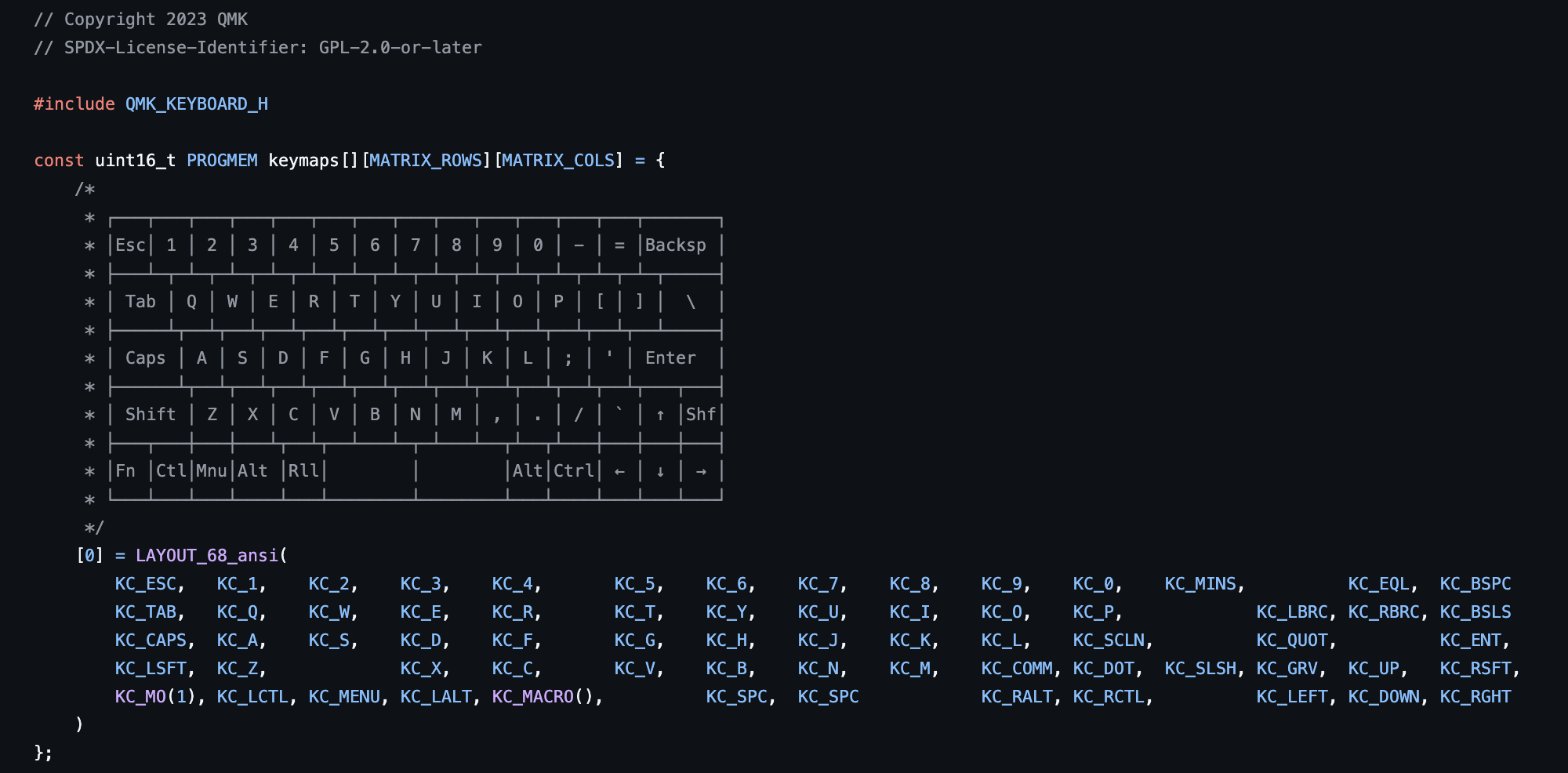
I also added the layout of the keyboard in the firmware file as in the image above, because why not.
It's kinda exciting, I'm so close to finishing.
I'm next going to add the mounting for the keyboard PCBs and I think that is the last thing I need to do... hopefully
Firmware: +3 hours
+3 hours
Time Spent on This Day: 3 hours
Firmware: 3 hours
Day 14: 30th July 2025
PCB CAD
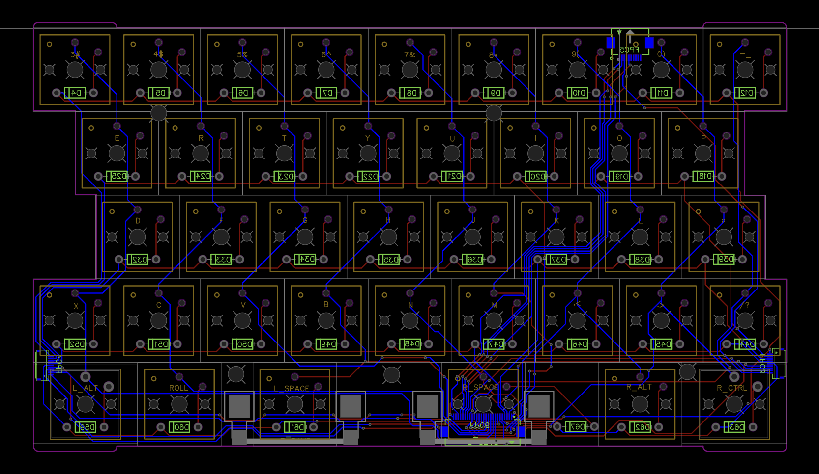
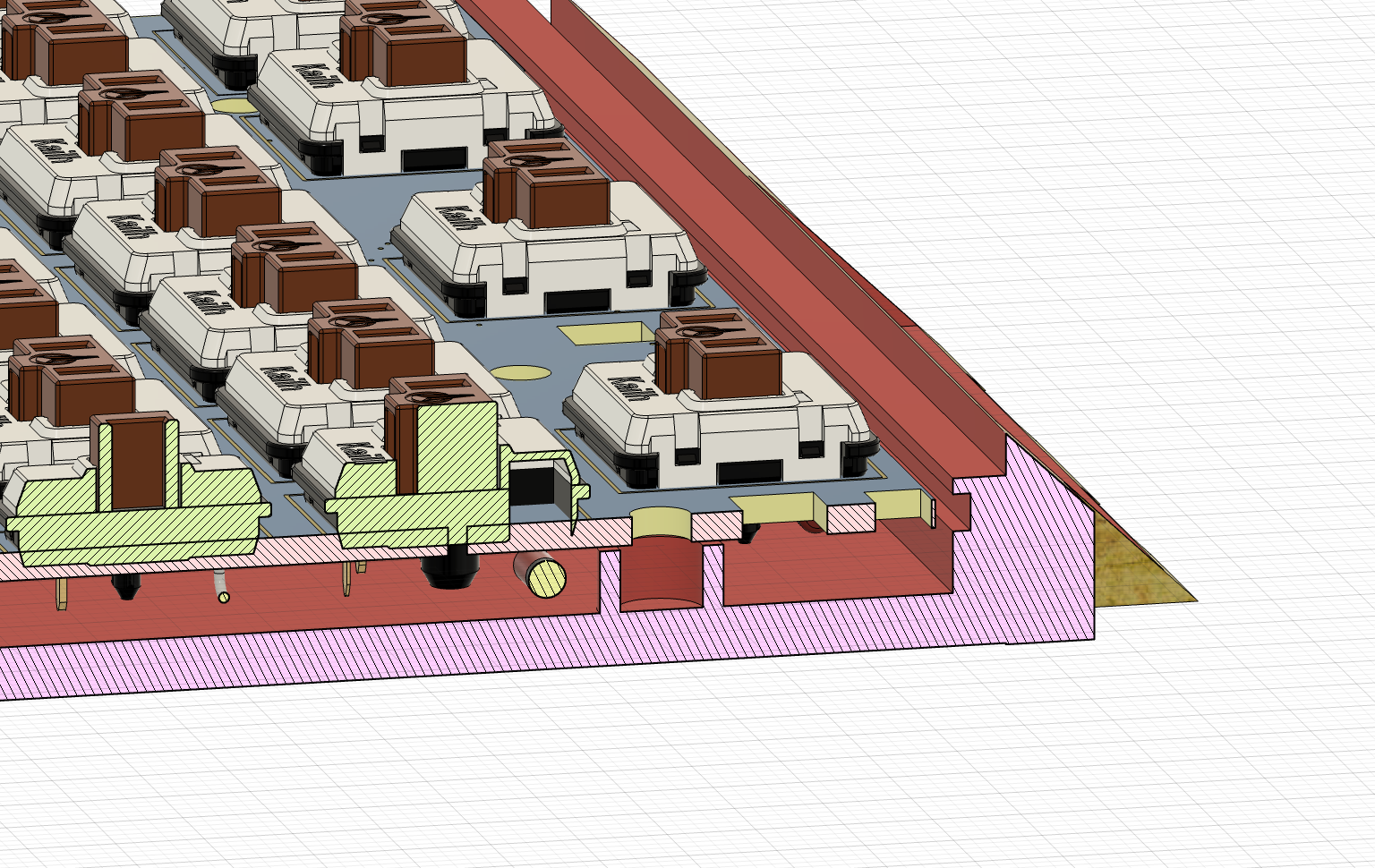
I added mounting holes to the PCBs so that I can mount them to the case:
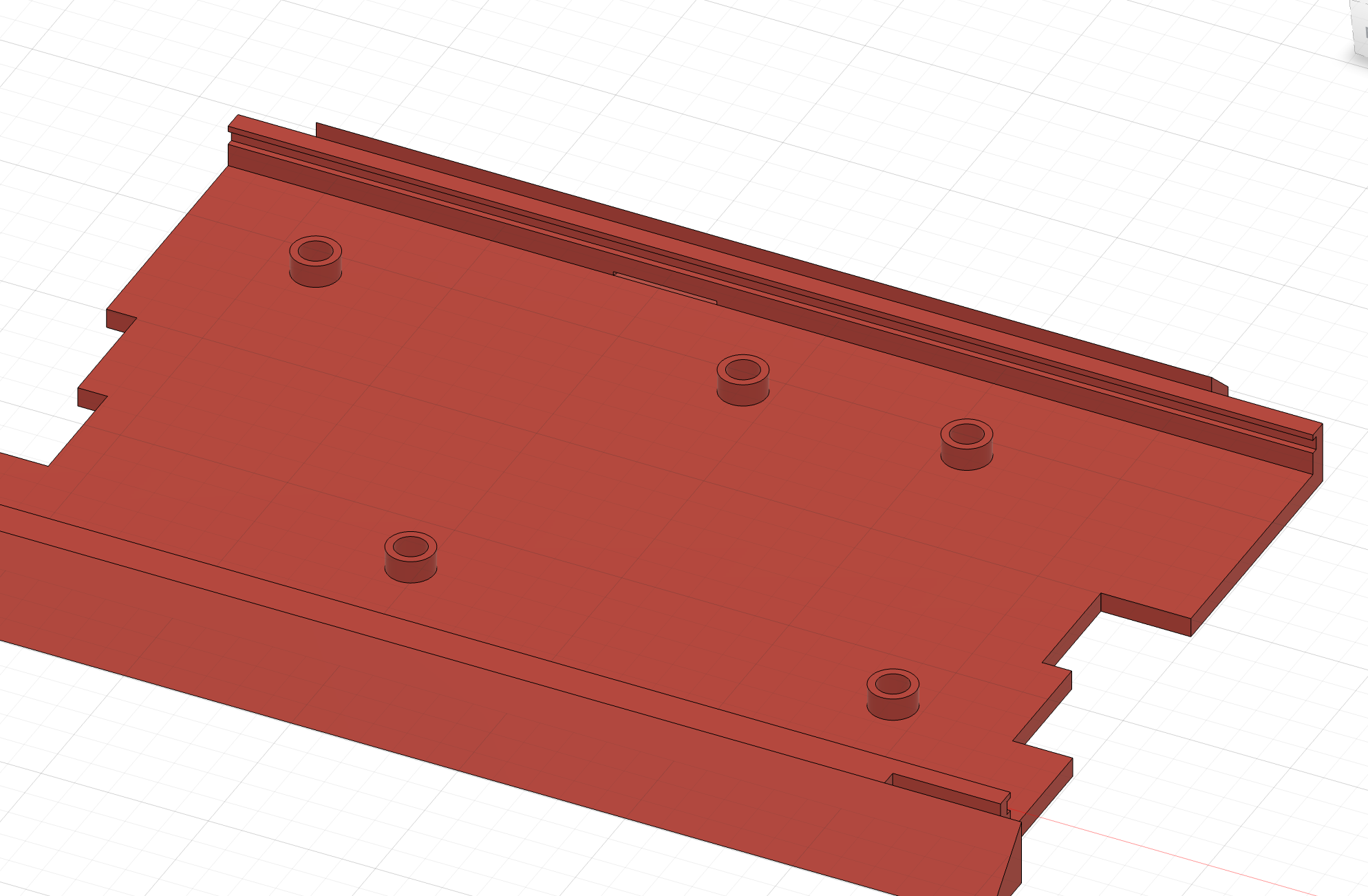
I then added corresponding mounts for it on the case:
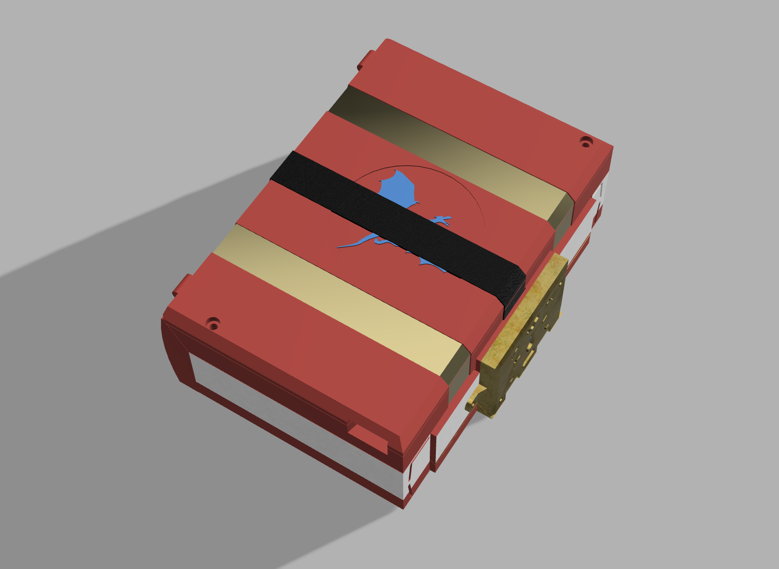
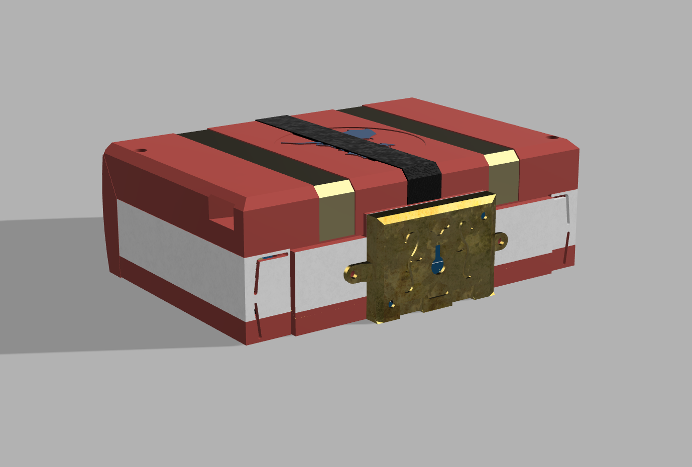
I have done some final renders of what the QuestDeck looks like and I'm honestly so happy with this!!!
PCB: +1 hour CAD: +2 hours
+3 hours
:partyingface::partyingface:
Time Spent on This Day: 3 hours
PCB: 1 hour CAD: 2 hours
