Homeassistant KEYBOWL
A keybowl designed for all your keys. But smart.
Journal
Here you can see a documentation of the entire development process.
Total hours spent: 26h
July 6th (7h)
Session 1 (2h) getting the idea, researching
After searcing for my keys and not finding them in our key bowl
I got the idea of a smart solution for our keys. And even better how to integrate that into Homeassistant. Forst of all the concept. So the normal non smart version is preitty simple, just toss all your keys into a borwl/ basket but what if every keychain had an RFID tag on it? This would allow for thracking the keys not neccesarily to spy on wh is home wut to knwo where the keys are. To step it up a bit this could also be integrated into Homeassistant with a small display that shows some data/dashboard per user. Everyone has his own keychain so I can track who tossed his key in or took it out. And based on that information everybody gets shown his own personal dashboard. For one it might be stats about our greenhouse for the othe their timetable and current changes of it right in the morning before school.
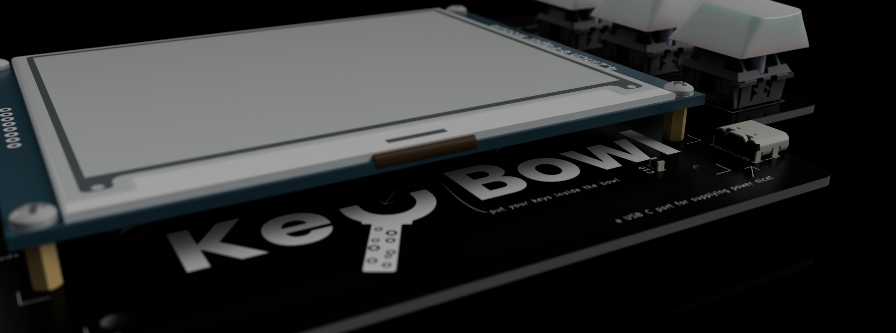
I wanted a simple non distracting and simple solution that doesn't uses to much power and in standby mode maybe can be used as a clock. So I opted for a 4.2 inch e-Paper display and a raspberry Pi Zero 2 which is relatively low cost but has enough power to handle all the stuff of the display, additional keys and RFID reader and can render beautiful layouts on the screen. An ESP32-S3 simply cant handel all of that in an easy way. Another chalenge was finding the right module and corresponding RFID Tags. NFC simply wouldn't cut it here. I needed a solution that can read multiple tags at one inside a pile and that without errors. This lead me to the R200 module a UHF RFID Reader.
Session 2 (5h) starting PCB design
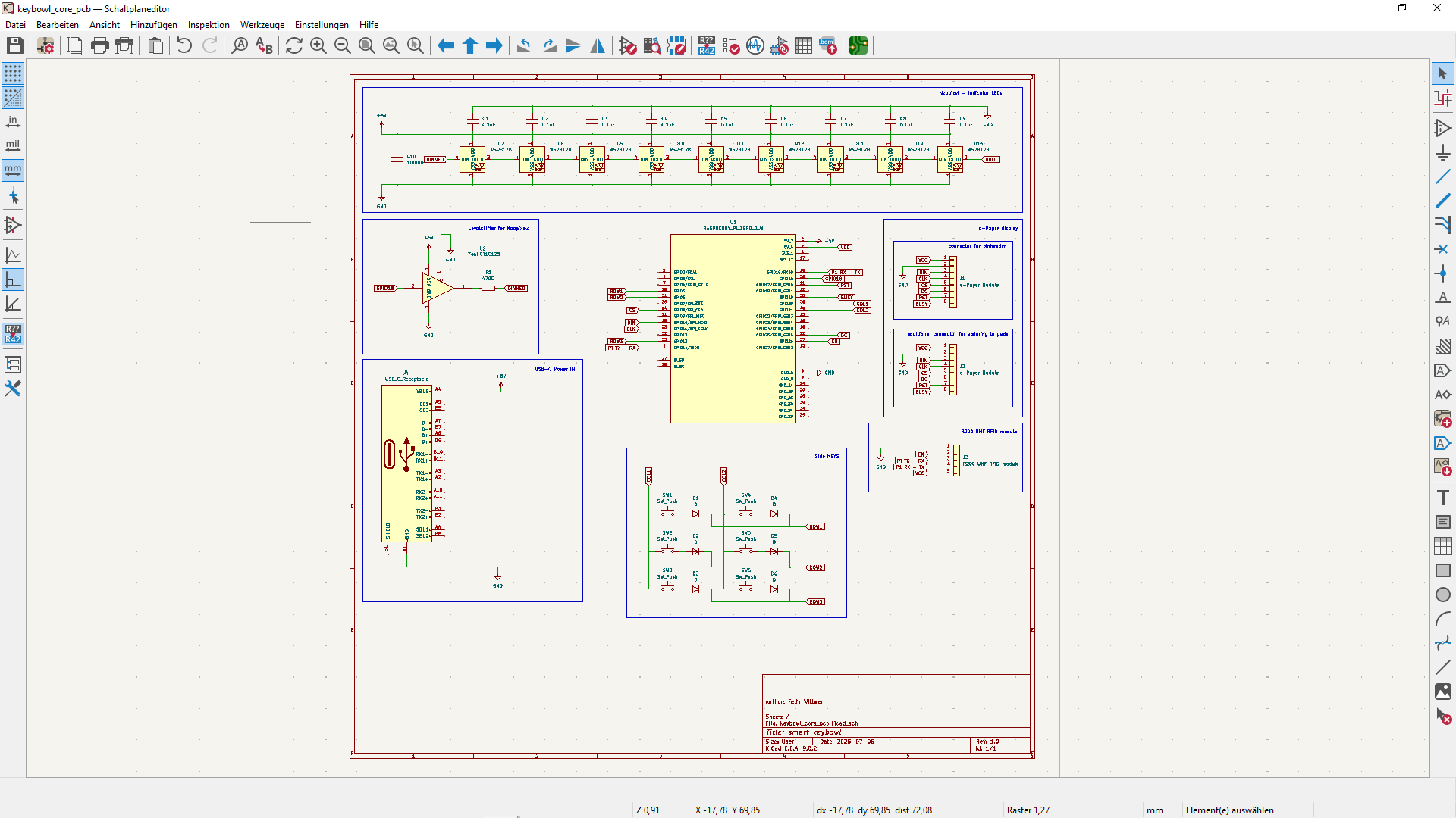
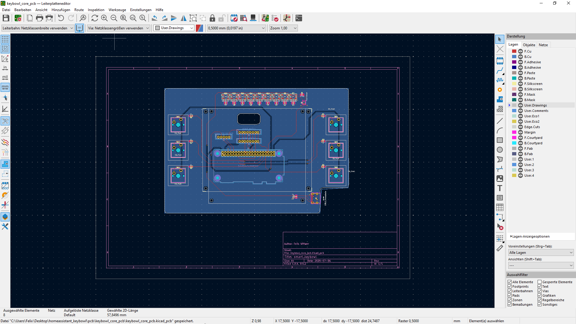
After researching all the parts I started with the core PCB which is kind of a HAT for the Raspberry Pi Zero 2 and will be in the middle of the case. Everything else will be designed arround it. To make it a bit extra I added a bar of neopixels above the display this will later be usefull to show status or be indicator LEDs. Because I quite like habtical buttons I added three on each side of the display. These will later be for navigating on the display of showing specific dashboards. These additions make the whole thing a bit mode interesting so now it is not just a display
:).
This time I really tried making my schematics a bit better than the last one. I think it is quite organised. Another challenge for me was learing on how to use a ground plane which I have never done befoder but eventually got it working.
July 8th (2h)
Session 1 (1h) adding some branding
Every project need some branding and I need some logos to make the PCB beautiful :). Logo is made with Inkscape.
![]()
![]()
Session 2 (1h) working on the PCB
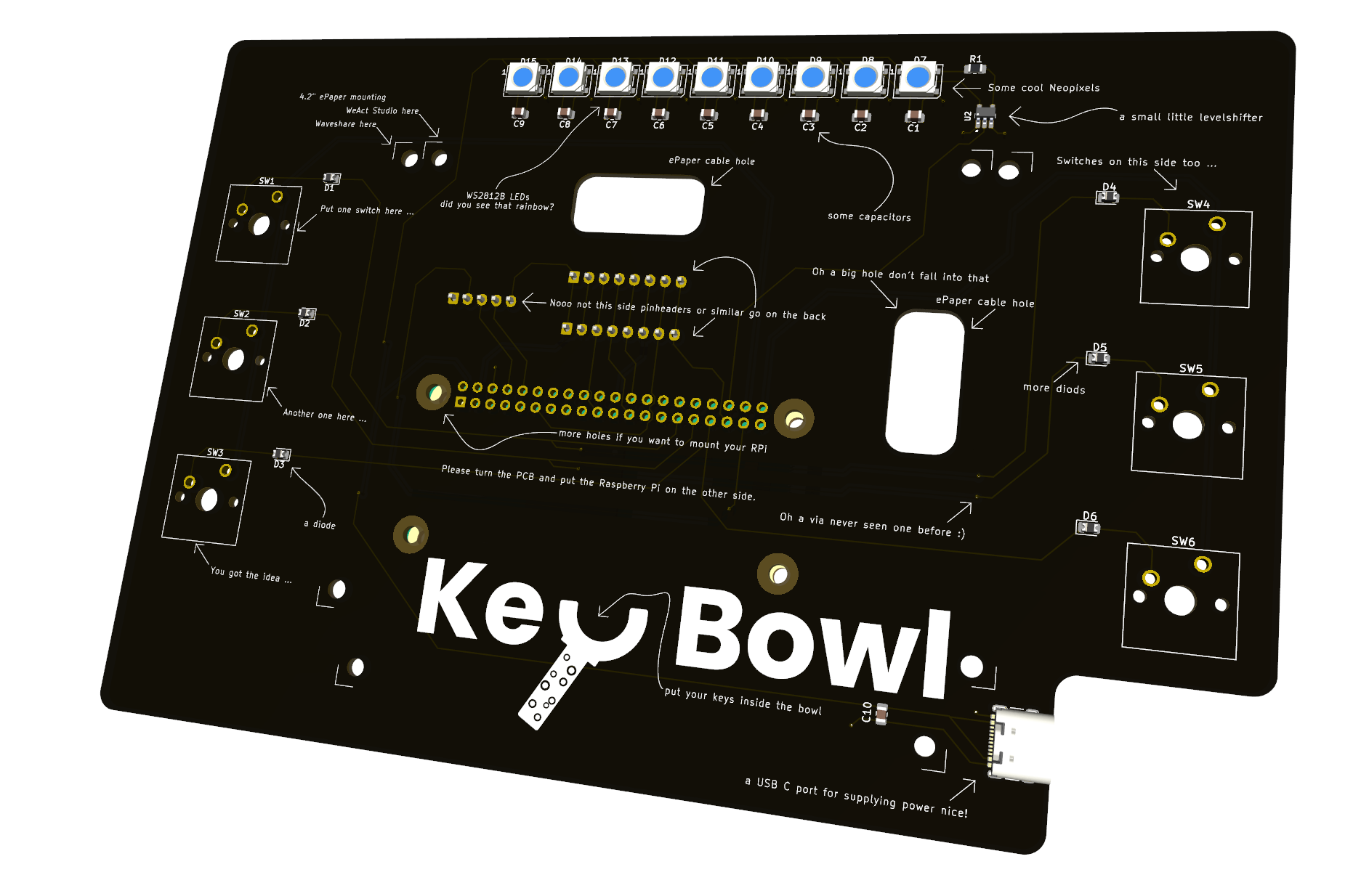
Now with a cool logo I could work further on the PCB. After adding the logo it seemed still a bit empty to me so I added some cool notes. If somebody else that me is going to assemlble this he is going to have some fun. AN jeah I defenitely discovered the path feature for the siklscreen lines/arrows. Some engenieet at JLC is going to get crazy after seeing my silkscreen :).
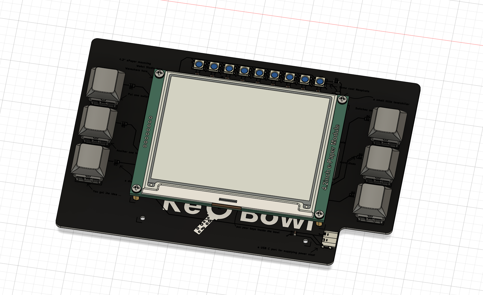
July 18th (1h) assemble pcb in Fusion
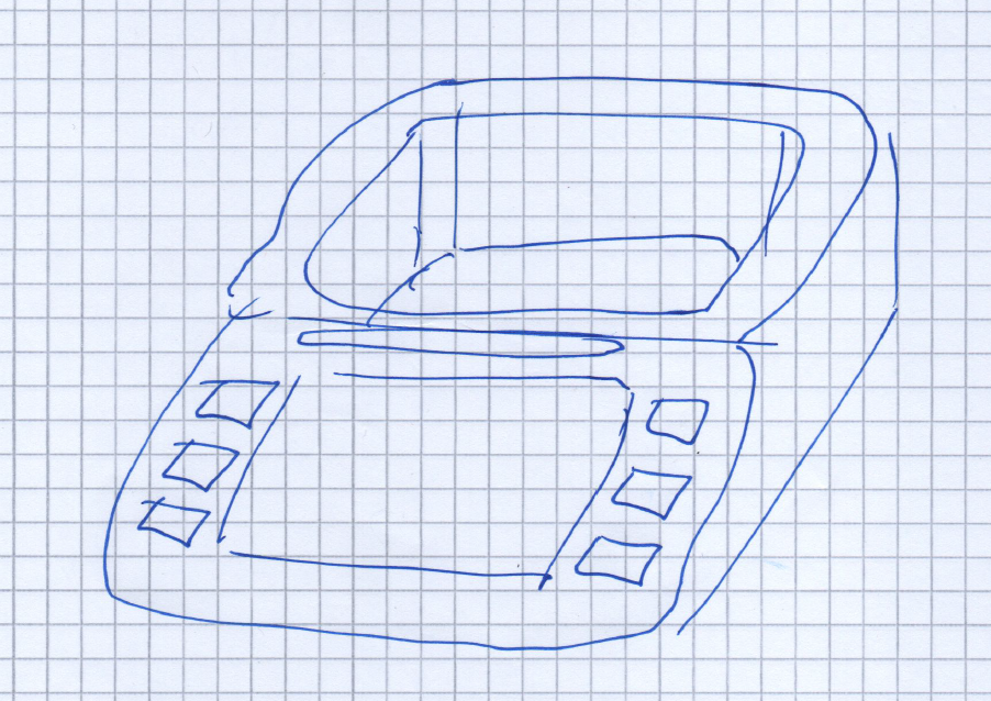
Today I just exported the PCB from KiCad as a STEP to Fusion and sarted putting all the pars on it. The next step will be to design the keybowl itself and place the PCB inside. The Keybowl itself will porbably be made out of Wood with some small 3D printed parts like a bezzle around the screen and keyswitches.
July 19th (5h)
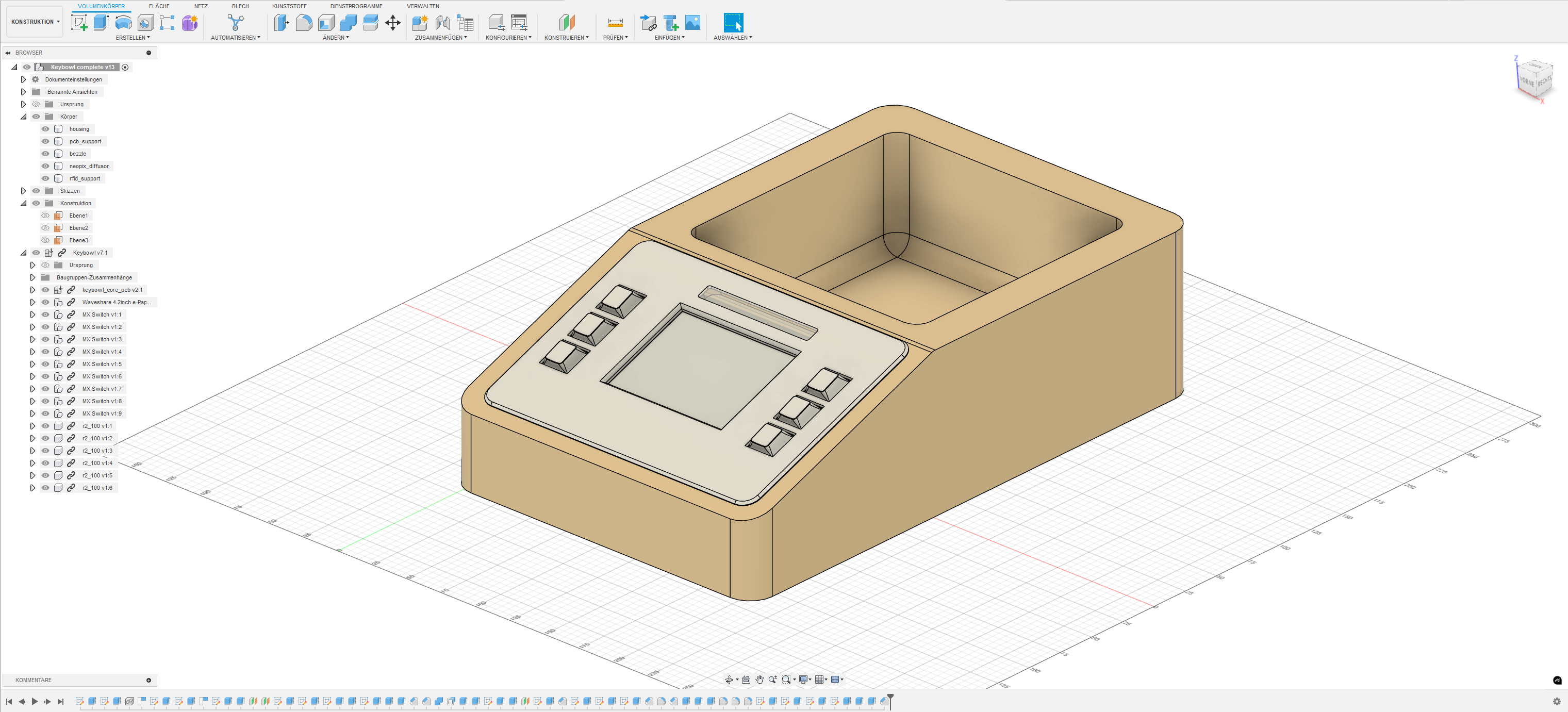
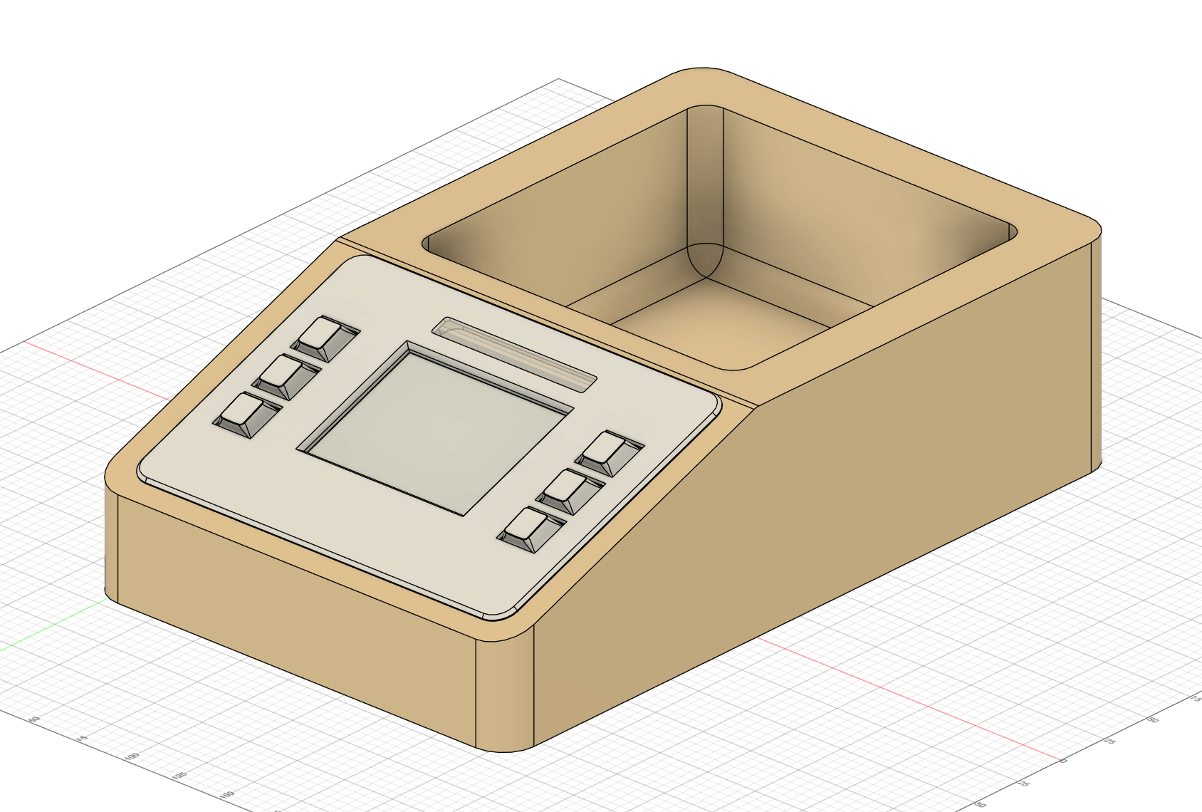
Session 1 (4h) modeling the case
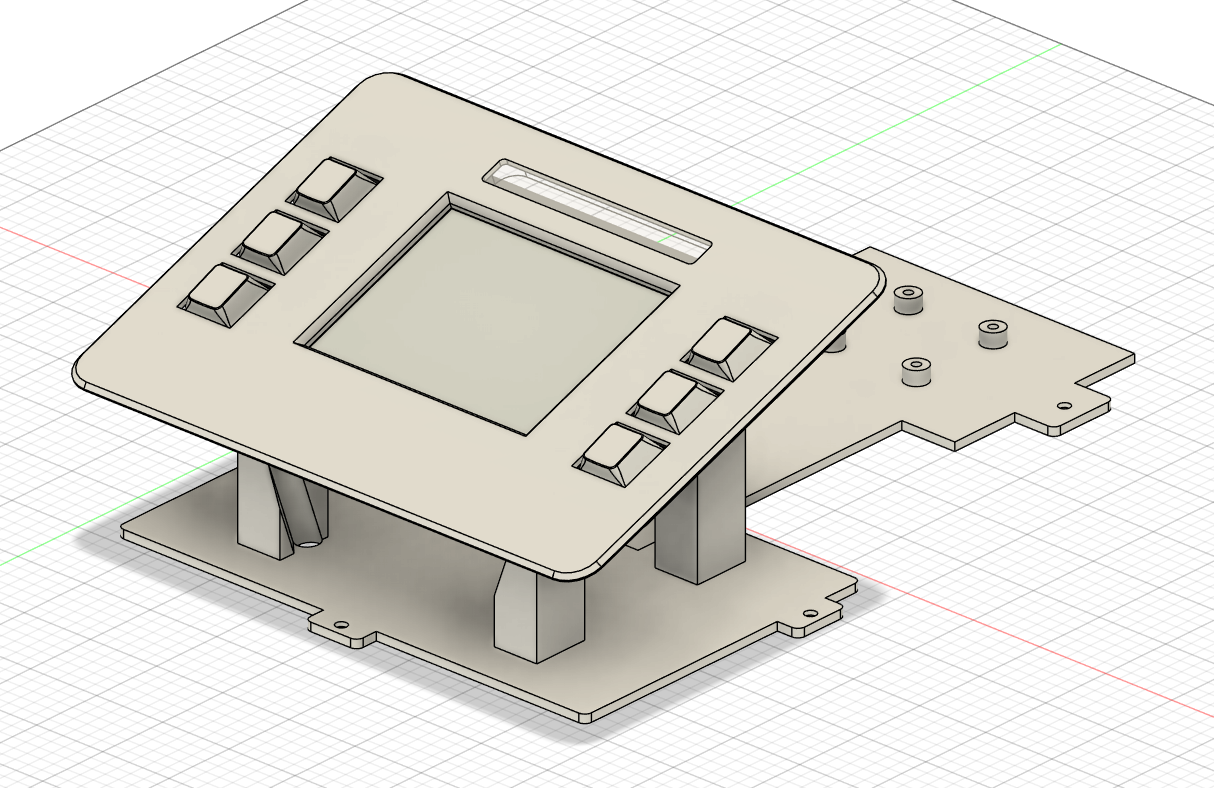
After creating a model of the assembled PCB I designed a housing around it. The main hosusing will be made out of wood only the parts for holding the PCb, RFID reader and the bezzle will be 3D printed. I designed the bezzle in such a way that it lays over the part that will be removed with a roter so if I mess up there it is at least not hidden. The parts fo the PCB and RFID mounting are also seperate to that these can be changed independently. So if someone chooses a bigger RFID reader not the whole structer needs to be reprinted. It also took me a while to figure out how I can mount everything while also making it possible to assemble. If the PCB is mouted inside the housing you can not reach the screws of the bezzle. Therefore I mad some additional holes inside the mounting to make the screws actually reachable.
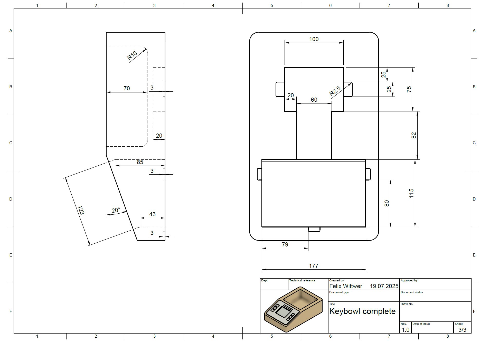
Session 2 (1h) creating production files and manufacturing instructions
I hav now created a stl file and step file for each part so that they can easily be 3D printed. Because recreating the woodden base if you have not designed it is pretty difficult I created some drawings with whom anybody can build the main housing. If you have large enough 3D printer you could probably also just print it but wood looks a bit nicer.
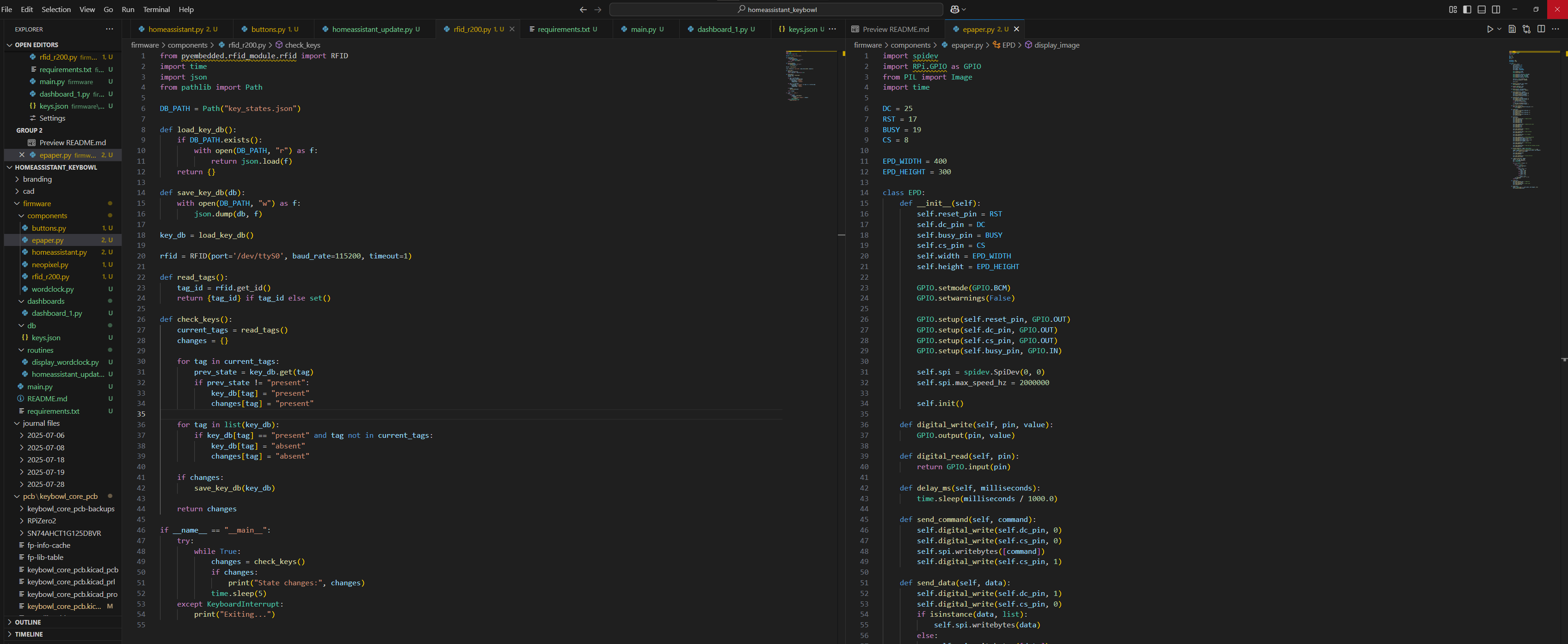
July 28th (7h) writing the firmware
Since all the CAD and electronics are finished I only needed to write some firmware to make the project almost complete in terms of the planing phase. Say so it is not the first time for me using Python but I am defenitely no expert and creating a clean structure that I myself and also others could understand was dificult but I think I managed to put something good together. The firmware is relatively well structured and I added a README just for setting up and installing the firmware on the Pi Zero. During the process of writing the Firmware I even catched a small error inside my scematics. Fortunately it was not something that would have broken the pcb but defenitely something that willl have confused someone that knows how to read schematics. :)
July 29th (2h)
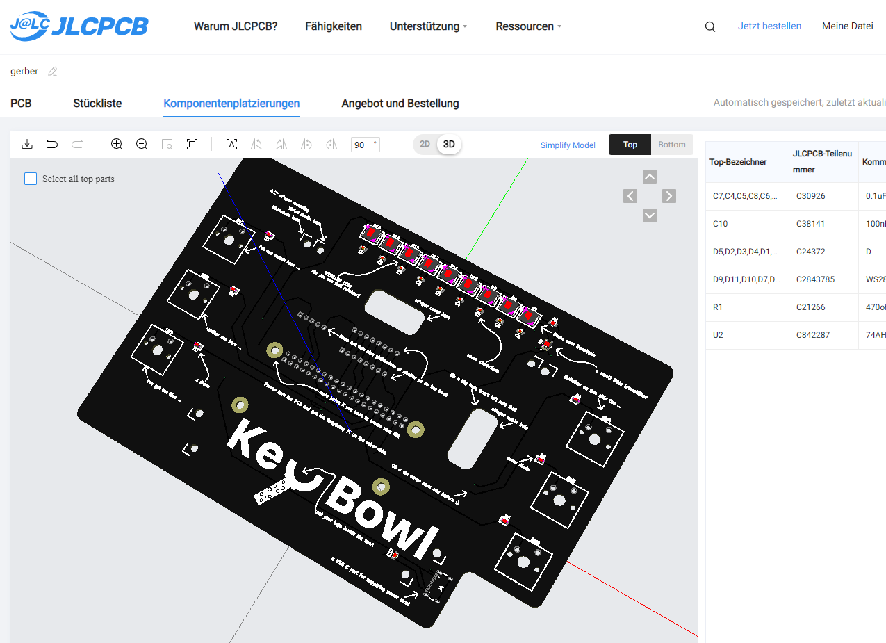
Session 1 (2h) creating production files especially for PCB assembly
The final thing taht needed to be done for production are the gerber, bom an placement files for the PCB. creating gerbers is a nobrainer for me since I have done it many times but making everything work for PCBA is sometimes a bit difficult. numbers have problems with their seperators, rotation or and placement of the part is off ot the package size is not matching. In the end it took me two hours to get everything right.
Session 2 (2h) getting ready for submission
For the final submission there are some things that need to be done besides creating the production files. I also wanted to create some cool renders for my README to show off the PCB I made. The rendering of wood in Fusion turned out to be ugly so I decided on just including a screenshot of the final CAD model.