
Highway Qrp Sdr
I got my amateur radio license late last year, and have been itching to use it more since then. I've decided this summer to work more on using it, but to that extent I need a radio. CW (morse code) seems pretty interesting, and working on the long range HF bands seems like a fun challenge, so I decided to build a 5w CW Software Defined Radio based off the RP2350 chip.
May 14
Highway kicked off today, and with it come many new projects. I've never built any kind of RF device before, so this is entirely new territory for me. I decided to do some research into the general design of a transceiver. The first thing that I've found is a series of schematics from QRP-Labs that details their QCX-mini transceiver. I then found a series by HAM operator Ward Harriman, AE6TY, detailing the design of a QRP SDR which I have a feeling I'll be utilizing frequently.
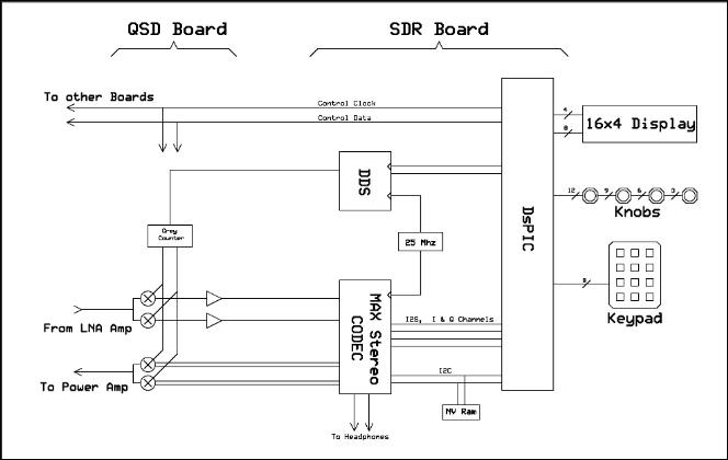
In his guide, he details a block diagram which I'm going to reference for my own board. The design I intend to use will have four main parts:
- The MCU, which will handle all the digital signal processing, IO to a display, key, etc.
- A
Tayloe
Detector, which will convert the RF received from the antenna into an I and Q analog input on the RP2350 - Filters, of some sort, on the transmit and receive (IDK I'm not an RF engineer).
- An amplifier on the transmit end, to bump the power up to 5W.
There will probably be other features, like a Li-Ion battery charger, but my final idea is somewhere inbetween the QRP QCX-mini and the HF Signals zBitx.
May 15th
Now that I've found some resources, I need to begin to plan my transceiver. The part that I'm most unsure of right now is filters and amplifiers, what I'll need for both and how they work. Looking at both the QCX-mini and the Pi-Pico RX on the receiving end I'll need a band-pass filter, so I'm going to spend some time learning how one works. After doing some research, a band-pass filter simply filters out frequencies that are either too high or two low based on a certain range of frequencies. I'm going to be making a single band transceiver, so I'll be opting for the 10M band. As an extra bonus, I had to fix kicad segmentation faulting when I tried to run it on Wayland with a Nvidia GPU :3.
Update after almost 4 hours of research
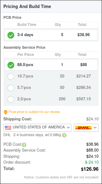
My initial plan was do to a custom RP2350 circuit rather than using an existing MCU like the Pi Pico 2, however PCBWay PCBA costs are far more than I expected, so I will sadly have to scrap that idea and look for solely THT or large footprint SMD components.
This does mean that my plan of using the SI5351A clock generator is in trouble, but thankfully Adafruit has a breakout board with the clock generator as a THT part. With these developments, my goal now is to use entirely THT parts for this PCB.
May 22nd
I'm back now after a bit more research and general life things (AP courses). On my search for THT components, I've found the 14529 chip, a dual 1:4 analogue multiplexer which will be the core of the Tayloe detector. I'm realizing just how useful it is to journal progress as I work, as it helps remind me what I was working on.
May 24rd
Working on the schematic again today, going to try and get the band-pass filter and the QSD made before I get called away again. I managed to finish the receiver schematic based off the QCX-Mini, although I'm slightly worried about certain parts that might be pull down parts since the QCX-Mini uses the ATmega-328P. But if they are I can simply desolder them, hopefully without damaging other parts during testing.

It's still missing a speaker output, but that should be easily doable.
May 29th
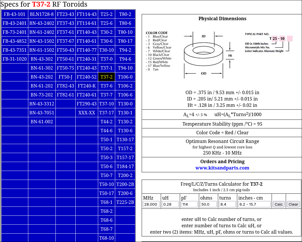
More delays due to the fun of AP courses. Working on the transmitter today, which should just be a simple FET transister to the connection between the Tayloe Detector and an amplifier for the transmitter. The first thing we need to do is make a switching circuit for when TX and RX, so that we don't burn up the RX circuits and cause noise. This is done with a simple quad-NAND IC. After that, we have the amplifier. I'm going to be using a class-E amplifier, which will require winding a toroid for an inductor. I'm embedding a screenshot of the calculations done for reference, as I know I won't remember afterwards.
June 9th
Back again, man this is taking me a while. Maybe I'll switch to another project just to have one done before the highway deadline. Anyhow, today we're working on the user interface, and hopefully starting the PCB today.
Time: 1hr
June 11th
I always say I'm going to do more, and yet here I am again :p. I'm beginning to wonder if I should turn this into a slightly different project of a morse code trainer instead.