
Diy 3d Printed Hotas Joystick
June 8th: Project startup
I started this project by just looking for some files and resources to get started. I found:
- The Olukelo gimbal
- The Real Robots Modular Joystick
- F-16 Sidestick Grip By Spock On printables.com
- Freejoy
along with multiple other videos about DIY Hotas's and even a Reddit Page
Total time spent: 4h
June 10th: Deciding on parts
I decided to use the Real Robots Modular Joystick For my Gimbal. I also decided to slighly modify this for my purpose and for easier recreation. The first modification was creating a hole through the joystick stick that connects all the mechanical proccess to the stick above There is already
Total time spend: 3h
June 11th: parts
I spent today just deciding what parts to use. For the buttons I was looking at 7mm momentary push buttons. I just decided on these because I couldnt be bothered finding 5 way or 4 way buttons. Also I ordered these just from temu just because they were cheap lol. I spent most of today downloading and installing
June 19th; Multiple days work
AFter printing the gimbal i found many flaws but i stuck with it and for the next week I tryed to get it working, after it braking wiht just 2 practice movements i knew something had to be changed.I 3d printed a smaller test version of the gimbal and I did not like the feel, and it was extremly limited and bad. It also used two potentiometers which were not even able to be read properlly due to the ADC's on my test raspberry pi pico not being ableto handle the two inputs which cross talk and lots of noise.
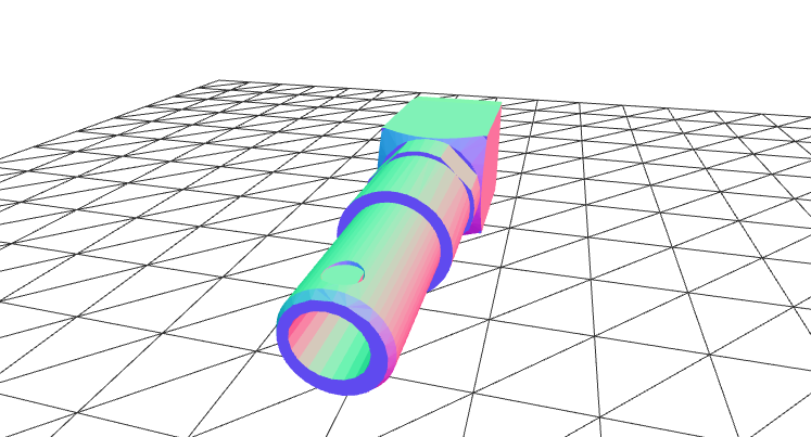
Today i have started designing my own gimbal. The plan for this is: - 3 Axis - with twist rudder controls: - easy to assemble - Cheap - Hall effect sensors for greater accuracy. - few parts. - easy configurable code/HID
So far I only have the first axis done. IT uses 688zz ball bearings along with a simple design. I am hoping to build on this adding multiple other life featurs
Total time spent last few days: 7h
June20th; Deciding on readings
I decided to use halle ffect sensors, i spent most of today just designing how I was going to mount them to the gimbal. The way i have come up with allows for adustment and easy maintenecce. I also imported the f16 sidestick grip as a refrence by spock. I hope to get the second axis done by the end of the week.

Total time: 2 hours
June22nd: 2nd Axis completed
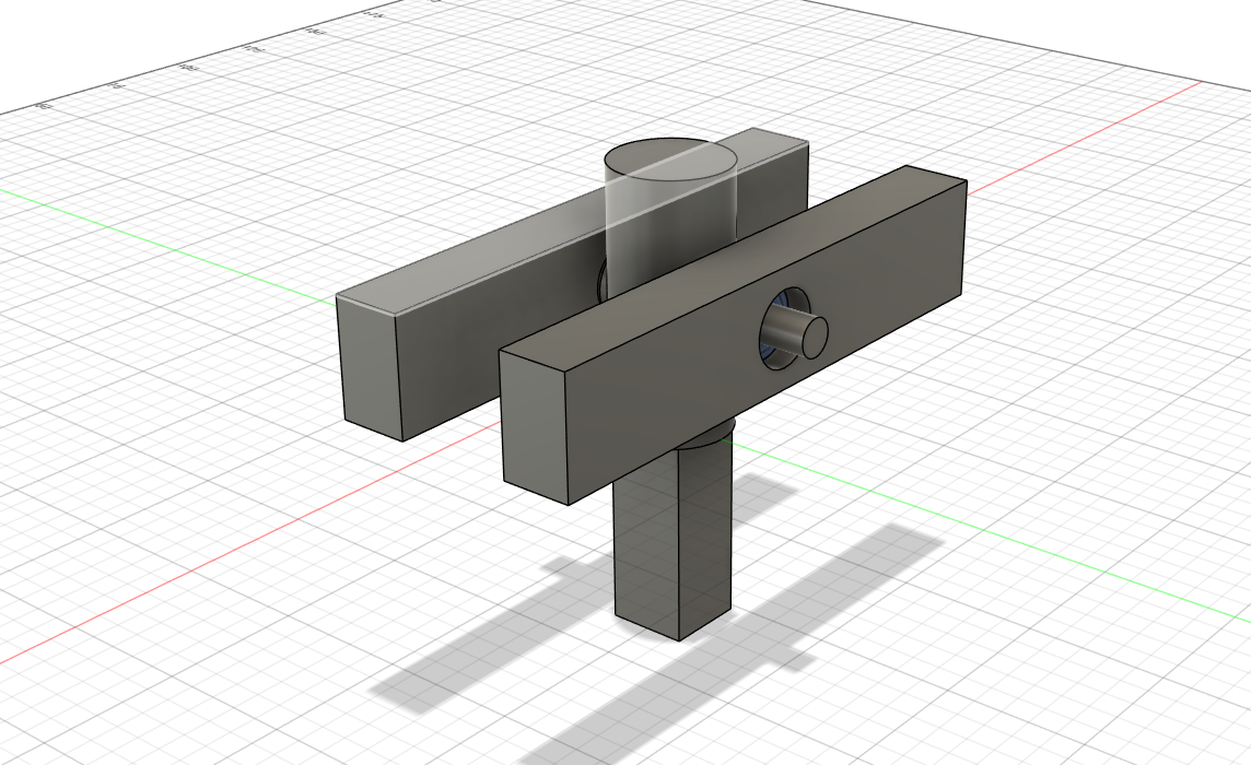
I started today by prepping thee gimbal for a 2nd axis, doingthings like adjusting sizes to how big i want it to be irl, and deciding which bearings to use (688zz ball bearings) then i modeled the 2nd axis, which was quite easy because I just did it trhe same as the first. The luttle L shaped pieces are going to have magnets either side and the hall effect sensor in the middle which is how i will get my readings. I also added screw holes to cerrtain places that nedded them and tommorow I am going to try and prep the model for a test, by adjust things aadding scre holes and finalising. Then I will start the twist rudder controlls. I also decided to go with a circular base, just because I think it looks cool.
total time: 4h
June 23rd: SMALLER!!
I spent today making it smaller as ther was lots of unnescacary space, I have noew reduced the outside circle diameter to 165mm which is much more bareable than the 230mm it was befroe. I also Added screw holes in different places, as I had to cut up some pieces so I can assemble it, I also added joints in Fusion and simulated the 2 degrees of freedom which worked quite nicely ( although sdtrasining my pc) I have left enoug room for 20 degrees of rotation in each axis (+/-) so 20 degrees forward and 20 back so 40 in total, I decided on 20 because thats what the Thrustmaster Warthog uses and I am trying to base this off that.
Total time: 1 hour
June 24 - 27th
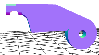
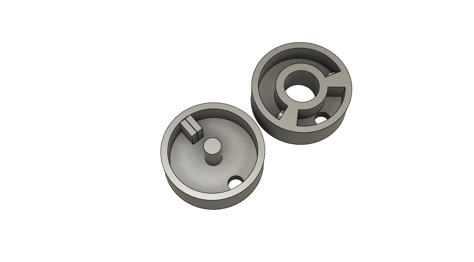
Not much happened on the 24th and 25th but today and yesterday I have been hard at work working on he twist ruddeer controlls. After some consideration, I decided on a small form simple design. The little raft in the middle holds 2 springs, one on either side, and when you rotate it it compresses one of the springs, applying tension and force back. The little holes on the opposite side are just palceholders at the moment, as I kind of need to print this and test before I decideo on how I am going to mount the magnets and Hall sensors, Right now the general consessis is to mount the Hall effect sensor throug hthe little hole and have the magnets rotate around it. It turns out that calculating distances between circles and all that is much harder than what i can handle because its pretty much calculus and triganomitry.
Time spent 3 hours
July 10th
I have been away for awhile so havent gotten much done. Anyways, I spent today dciding on how I was going to have my springback return to center mechanisms. I origianlly thought I would just have four springs like in this image:

However after modelling this on my gimbal I decided that it would not work because My gimbal was mroe based off of a 2 stage kind of platform. So i kept researching. Then I looked at other gimbals such as the olukelo one and all of the good gimbals seemed to use a CAMS
which are htese mathematical driven curves based off of spring tesntion feel and other fancy math stuff. THese are great because you can adjust how different parts of the stick feel. EG the center feels soft and the edges harder. However, I could not figure this out for the life of me so I decided to go with a basic SCissor type springback for the time being as it would be easy to model and test out.
Total Time: 5 hours
July 14th: Parts, Keyfacotrs and Concepts.
IT turns out that the hole sciossor thing is harder said then done and would easilly be the hardest par of the project. SO I got right to work. SO first up I decided on some parts. I wanted bearings for a smooth finish and I wanted the scissors to be 3d printed. The bearings I decidede to use are 623ZZ Ball bearings. I just chose these becaause they were are good size.
I spent the rest of today drawing some concepts and plans before hopping into cad. I figured out that I would need three bearings per Axis so that is a shame it will definitly add up to the price.
TOTAL TIME: 3 hours
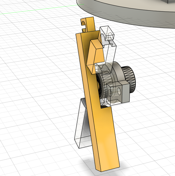
July 20th: long hours on CAD
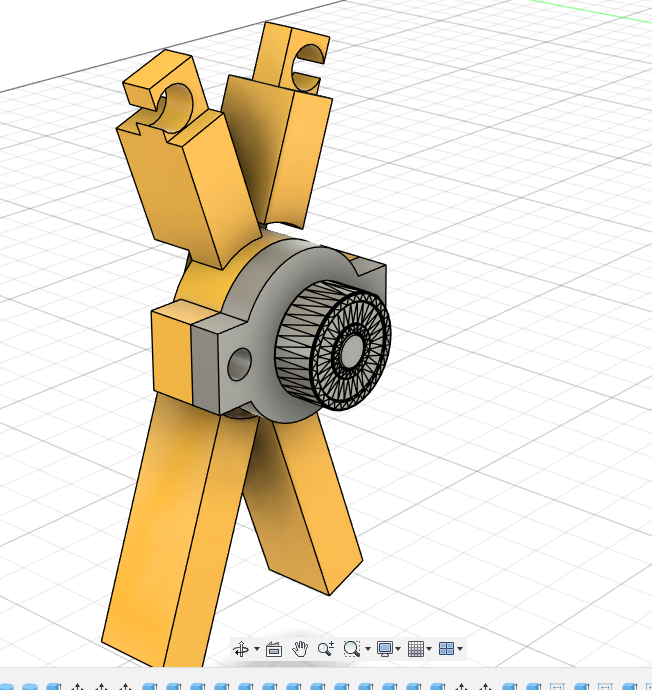
I spent the last few days modeling the scissors, mechanisms and beaerings in fusion 360. This has taken me awhule as I am pretty new to CAD only picking up fusion a few months ago after only previously using Tinkercad. Below is the design I came up with. THe hooks ontop being for a rubber band or spring and the two bearings inside.
Total time spent: 7 hours
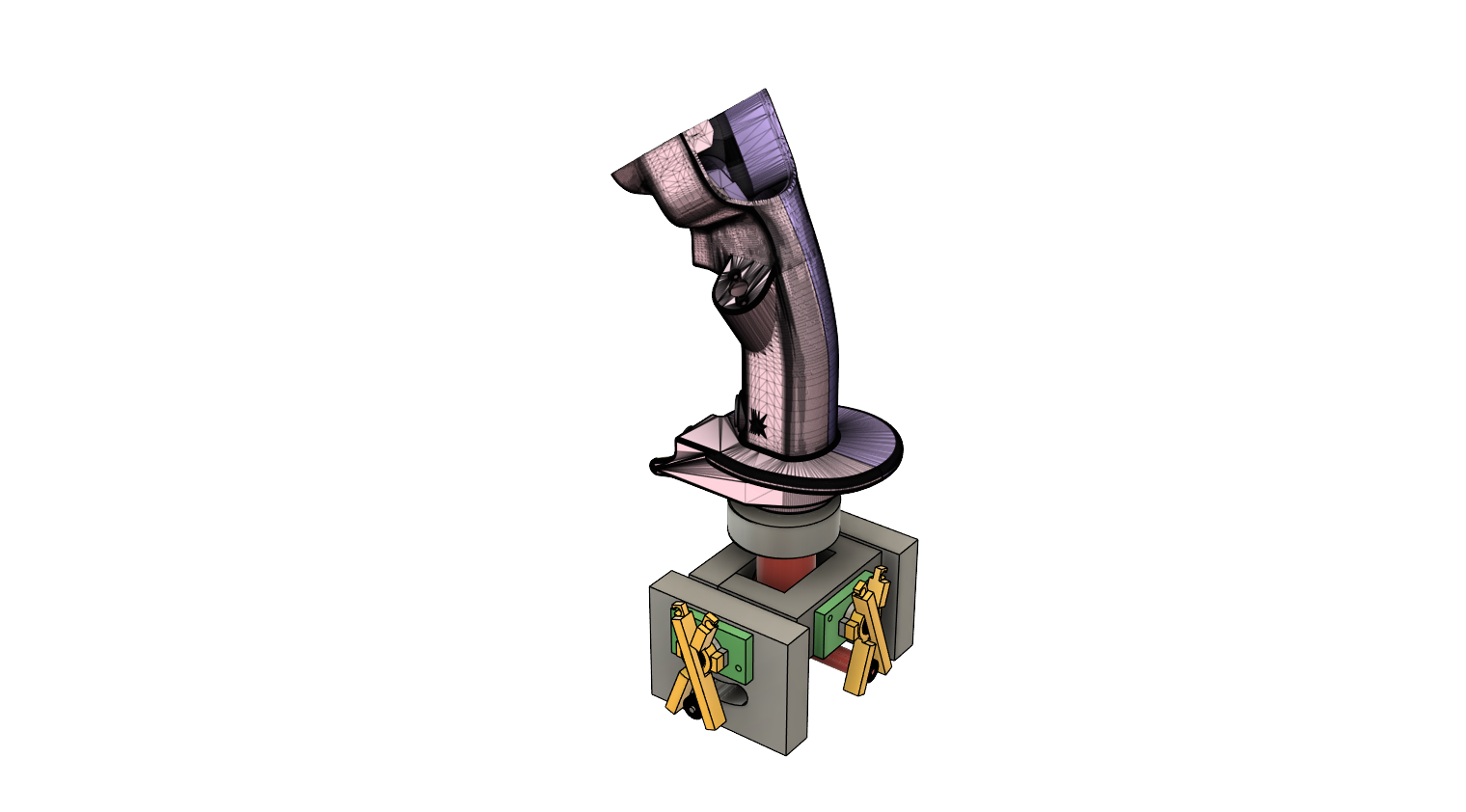
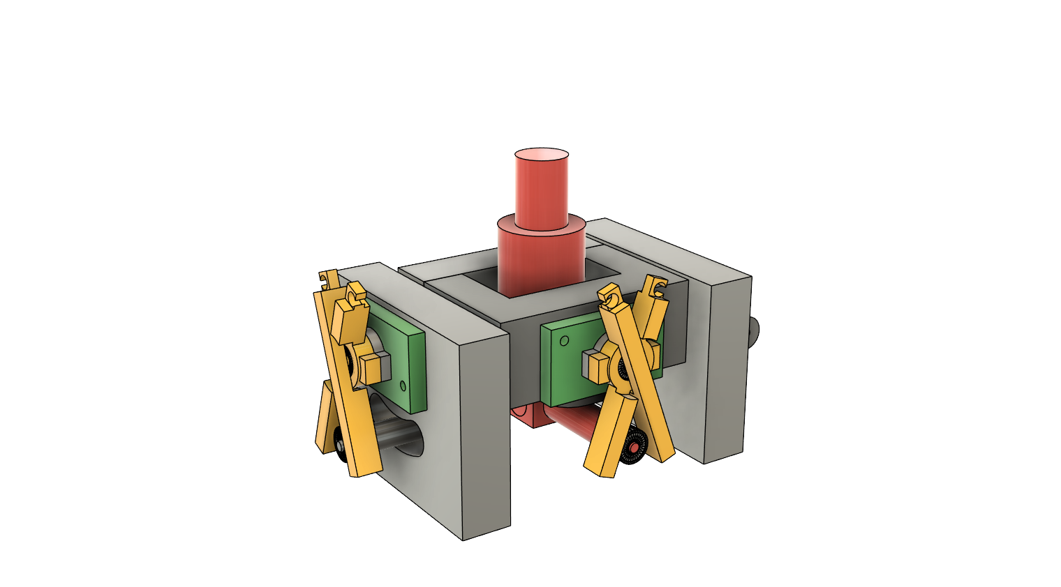
July 21st: Final touches.
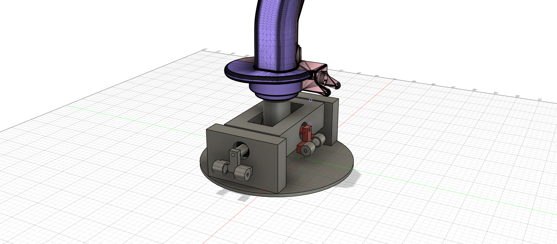
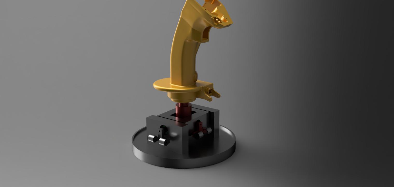
Now that I am essentially finished with the gimbal, all I needed to do was make a quick monting plate for the scissors, anad do some simlations and tests and It is ready for printing. I am super happy with how the 3d model came out. And cant wait to see it get made IRL and be fully working. Below are some images of the final product. The top image is the completed full joystick with the twist rudder and Jflyers f16 joystick mounted, although any joystick will do as it is quite easy to mount anything on there. The bottom image is just the Joystick
July 22nd: SOFTWARE!!!
I have spent all of today finding some software to use for this. I started today, by writing out some quick code for my ESP32, afte a few hours or so of testing and coding in the arduino ide I relised this was super flawed. for the following reasons.
- There was absolutly no filtering.
I tested this with just some basic analog potentiometers as they are quite close to the analog ss49e hall sensors I will be using. Anyways With having three potentiometers I noticed some mad crosstalk and noise, to the point where it would be unuasable. So i spent another hour trying to add a kalman filter only to give up. - Most controllers have a sort of deadzone.
Most controllers such as a ps5 dualsense or even some hotas's have customizabile deadzones. - Axis curves.
Some Hotas joysticks and controllers have stick axis curvers which allow for a smoother feel and lesschoppy
respons.
After relising all this and relising that this would be very hard to code for an esp32 I decidede to use something else.
What I landed on was an STM32 Running Freejoy. Freejoy is an open sources software for stm32f103c8 Blue Pills. I chose this because it was super customizable, With a software called FreeJoyConfiguratorQT which lets you set up all kinds of different things such as axis curvers, deadzones and filtering along with calibration for analog axis. I saw this and thought it was perfect so tommorow I am going to try and quickly flash it to my stm32 and wrap this project up.
Total time spen: 10 hours