
PiRPKey (PRK) Security Key V1
A small, fully-open-source security skey upporting multiple protocol (WIP project)
Journal
Total : 17:20 hours
Day 1 (26 May 2025)
Read about FIDO U2F and WebAuthnn https://www.yubico.com/products/how-the-yubikey-works/
Today I started planning/bbrainstorming/researching for my project. I tested Fidelio on my Orpheus Pico to learn more about U2F/FIDO. I'm also following Raspberry's official Getting Started With The Pico guide to learn how to use it and program using the VSCode extension.
Research : 1:30 min
Code : 30 min
Day 2 (28 May 2025)
I'm trying to get my Orpheus Pico to print on an LCD 16x2 (non I2C). It may seem odd but that's because I'm (trying) to make up a hardware base to test a very rudimentary TOTPs generation mechanism on, and I need a display (technically could use serial but dispaly is cooler). I would really had loved to test o a 0.91" OLED (what I'll use for the board, when I design it), but I don't have any so I'm forced to use a 16x2 LCD.
Saddly it doesn't seems to work at all. I tried this libary with some minor modification to the circuit. I'm really stuck so I tried on an Arduino Uno with the Arduino IDE/libraries (good ol' Arduino). Work fine, with the exact same LCD and circuit (had to change the pisn in the code that's really all)
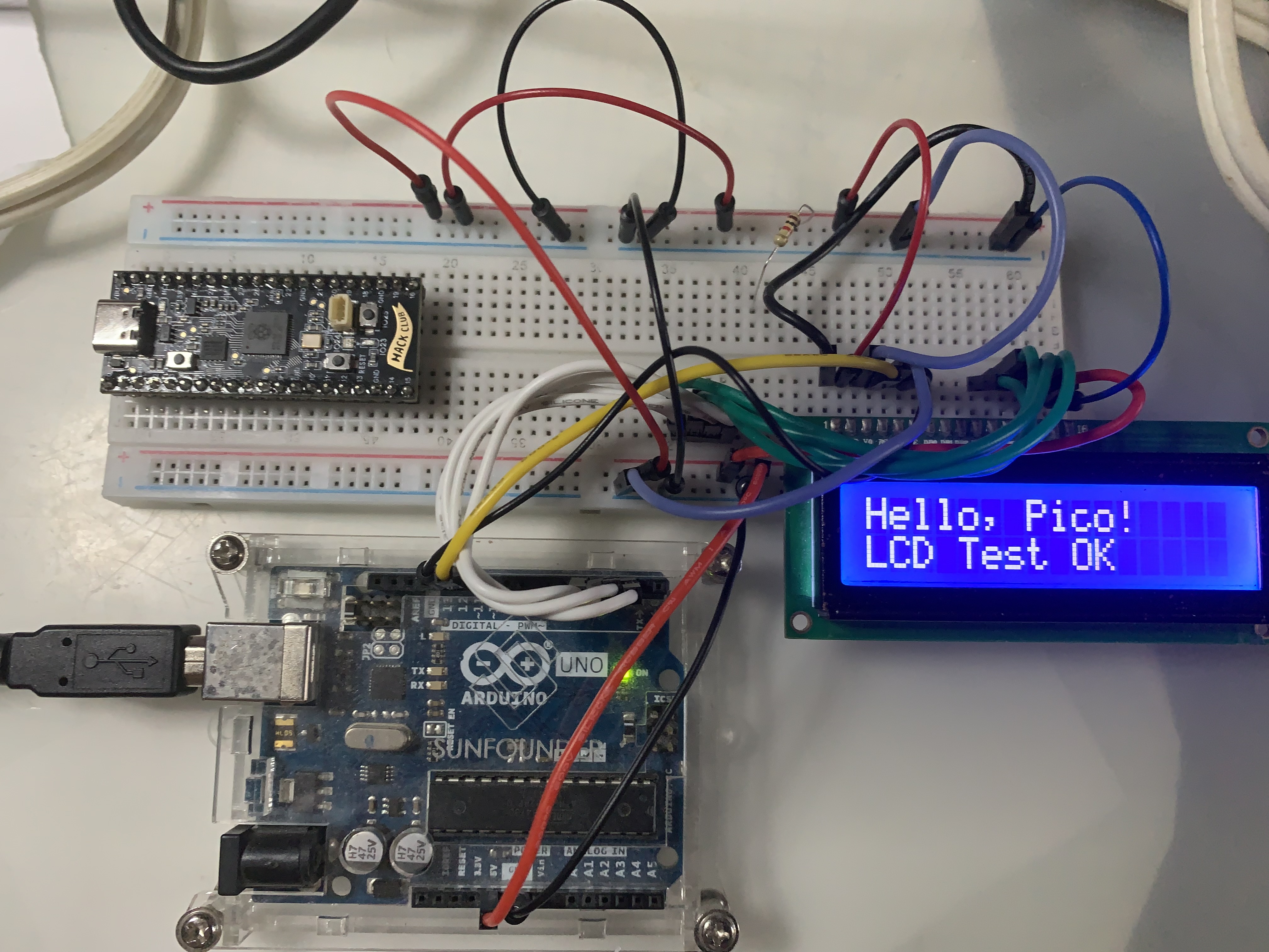
Arduino running the LCD beside the non-working Orpheus Pico
Finally, after asking my favourite AI, Perplexity, to try to help me debug, it gave me a fully-contained code and circuit that worked. I'm not 100% sure if the problem was hardware-related or if it was just that the library's example I used was not okay, so I'm trying to test other stuff with the same pins.
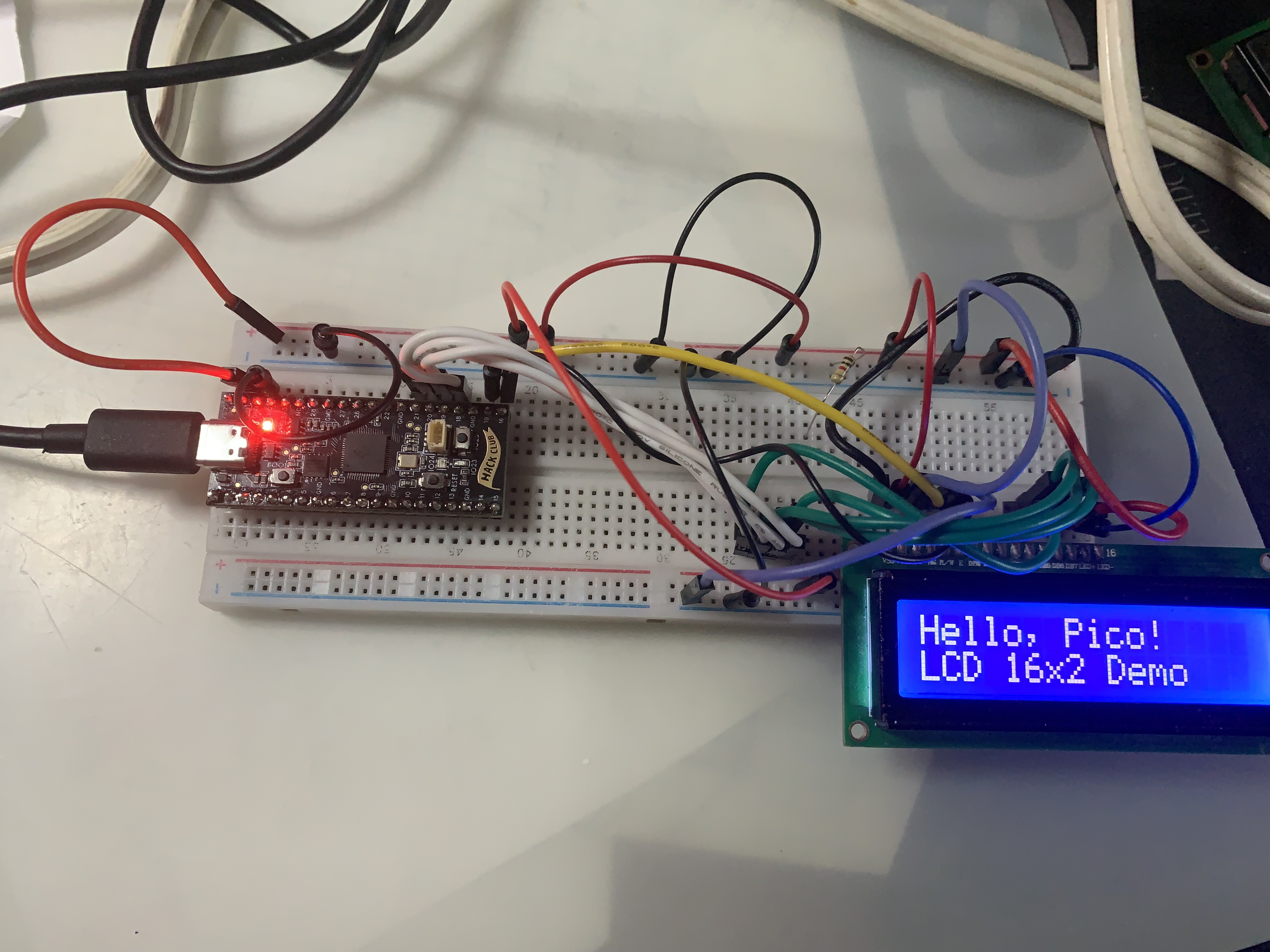
The Orpheus Pico finally running the LCD with the AI-generated code!! Wooo-hoo!!! 🎊
Even better, I tried to run a simple code from the Arduino IDE (that I configured correctly so I can flash the code on my Pico), and it worked even tho I tried the exact same code earlier but with different pins connected. The problem definitely look like it was some pins problem (either I wrongly connected wires multiple times in a row or the GPIOs that I used where faulty, I'm not sure
Here's the Arduino code I used :
```C
include
// Pin mapping: LiquidCrystal(rs, en, d4, d5, d6, d7) LiquidCrystal lcd(16, 17, 18, 19, 20, 21);
void setup() {
lcd.begin(16, 2);
lcd.print(Hello, Pico!
);
lcd.setCursor(0, 1);
lcd.print(LCD Test OK
);
}
void loop() {
}
```
Now I only need to test if the libary for the pico I mentionned earlier works now.
Electronic : 50 min
Code : 15 mins
Day 3 (29 May 2025)
So as my LCD fully work with martinkooij's libary and Arduino's one, I'm reasdy to start coding! AS I'm not really an expert in C/C++ I want to first try to make a small mockup of a TOTP generation mechanism, so very very basic, not encrypted in memory, etc.
The main problem is that the TOTP generation mechanism require the current date & time, but as there is no wifi, the time on the pico (and by extension, the board I'll design) always reset at boot. So either I will need to :
- Use NTP (but require wifi so i cant test on my orph pico, and my board will need to have wifi module so be bigger)/a onboard external RTC (again, will add to the size), or
- The user will need to set it up at each reboot (if I put a battery it shouldn't be that often but still), OR,
- I try to implement something to get the time via serial from the PC where the pico/key is plugged (but will require some sort of 'companion app'
Considering those options, I think that no 2 is the best for this use case. AS I'm just going to try to make a mockup TOTP generation thing on my LCD, I will just hardcode dates & time (as shown in RPI's official examples, in the future of course so it will ocver the compilation time, and i just fire up my pico when the true date come so it can generate TOTPs.
Code : 40 min
Day 4 (30 May 2025)
Today I decided that, beside trying to start the TOTP generation code, I will also try to start of the PCB design in KiCAD. To help me out, I foudn a few ressources, like RPI's official guide or this blog article, wich will highly help me making the basic (decoupling, wiring up the flash, etc), and that I will be able to use as a base for my project (like adding more inputs/leds, adding the OLED screen, maybe adding NFC support (if I don't leave that for the v2).
As I'm working on a USB-stick-format PCB I will use USB male plug (duh, who wants to have to use a cable to plug it to their PC), but most guide use female/receptacle USB. Normally I think I shouldn't have too much adapting the oen I choose, still new to that tho.
After using EasyEDA2KiCAD I was able to import the symbol in KiCAD. So I'm wiring up the connection in schematics.
Wiring up the USB-C was a bit tricky because from what I saw no guide showed how to wire a male USB C plug, but with the guidance of Perplexity I was able tp understand both how to wire up my specific model and what each pin mean (because they have different name than what's used in the guides)
At the end of the day, here's my advancement :
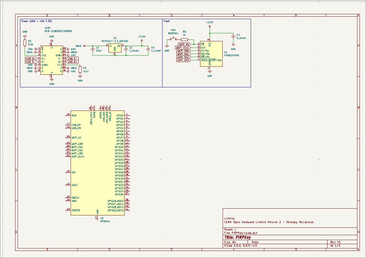
My schematic as of now 😁
I also found this awesome gist explaining what are Yubikeys
Schematics + Research : 3:00 min
Day 5 (31 May 2025)
Continuing my schematic, I now added the crystal as recommanded by the Hardware Design guide ( this one seems to be correct). I had some problem with my KiCAD's PCB editor (some kiface error), seems to be gone by updating my whole system.
When talking with @geschmit in the slack he made me realize something important : first the USB-C I choosed was for vertical-mount (💀 me), and second, USB-C male are really expensive to assemble by PCB manufacturer (like 50+ $). Because of that, I will switch to a USB A male connector (I want to keep the USB stick/yubikey format, so I don't want a C female)
So I need to review my USB connections and find a new replacement 😭
For now this look realatively okay, no Assembly : High
so I may take this one.
Continuing my design, I'm now asking if I should or not add holes for GPIO pins. It is not required for my design (the OLED will go directly to the RP2040), but may be cool to have if, after receiving the first batch of V1, I want to prototype more stuff.
On the code aspect of my project, I found this HMAC library for C/C++ that could be interestant to use for TOTP, before realizing I only need HMAC-SHA1 for TOTPs.
After some research, a result on the arduino forum got me annother libary : this one
Schematics + Research : 2:05 min
Day 6 (1 June 2025)
So today I started a bit late, so I decided I would work on the TOTP code in C. AS I said, I'm pretty beginner in C so all the bits/bytes operation, big endyan, etc where a bit too much for me, so I used AI to explain to me and guide me on what I need to do (hope this is accepted by Higway, to clarify I didn't generated the whole code by AI and just copy paste, I tried my best to code stuff, asked alootttt of explanation of what the code was doing, why we do liek so, etc)
Code : 1:20 min
Day 7 (2 June 2025)
Today I added an external RTC (DS3231) with a CR1220 battery holder to my design, after I saw this project, where I realized that an external RTC is clearly feasible on a small usb key amd it will definitely be worth it (users won't have to re-enter the date at each reboot). I tried searching some fingerprint scanner, only thing I found on JLPCB is this, which is small yeah, but not that much and seems hard to attach on a PCB. Maybe I just won't add a fingerprint scanner after all...
After talking to @acon on the slack I now changed my plan and I will try to implement the maximum of function I wanted to leave for v2 into v1 (as I don't know if I will be able to make multiple iterations). I also started adding much of my compoment's footprints to have a better global view.
Here's a screenshot of the current state of the schematics :
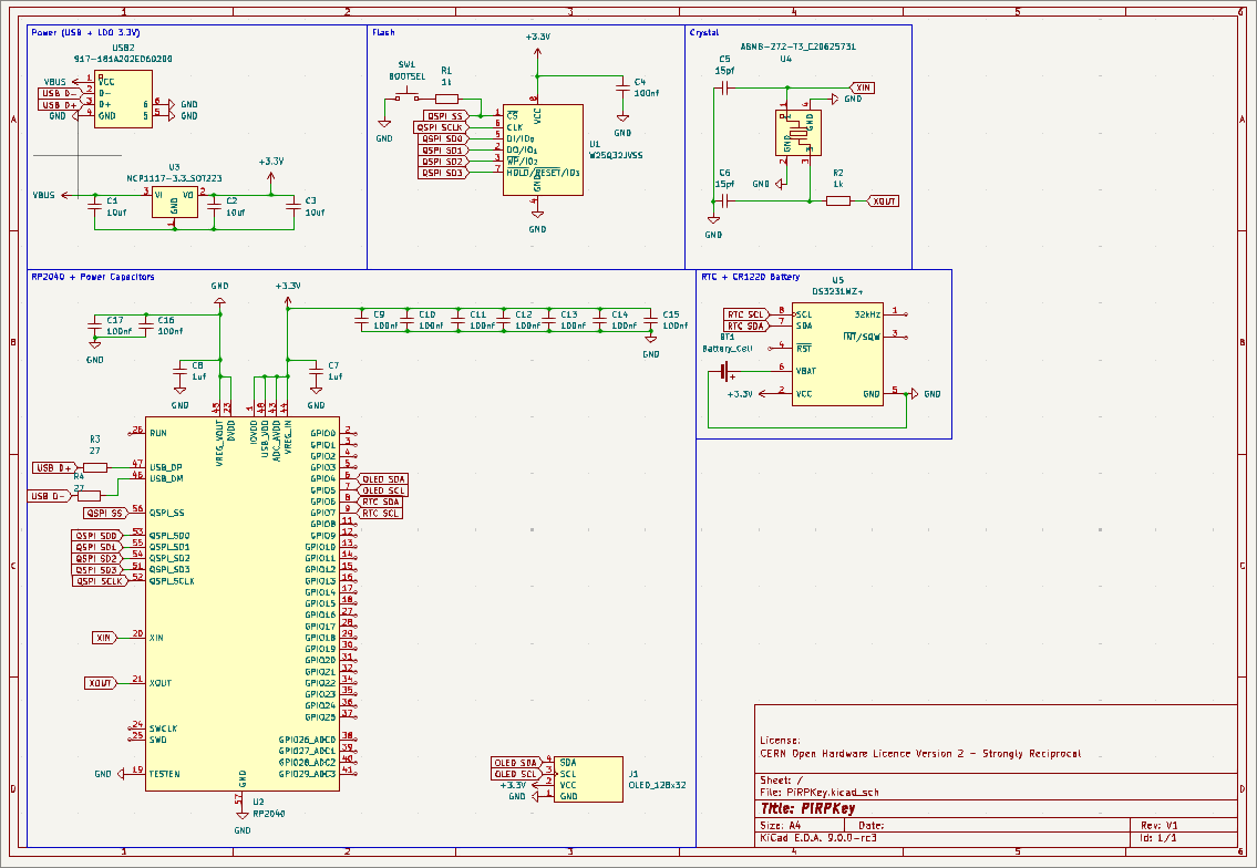
Schematic as of today (june 2 2025)
Schematic : 30 min
Day 8 (3 June 2025)
Today I (again 😭) changed my plan after talking with @Rudy on the slack : I'm goign to use a pcb edge connector for the usb instead of a metal shell one. I found the correct symbol & footprint on easyeda, exported it to kicad and now changed my design. Now I'm nearly done with the shematic, I only need to find if I will use a capacitive touchpad (like yubikeys does), a normal button or a fingerprint scanner (if I find any that fit). I also need to add some leds and it should be good!
Research + Schematic : 40 min
Day 9 (4 June 2025)
Big news : after soem research I realized that nor NFC nor BLE was possible witouth a battery. Which means that for non-usb-c phones (of if you dont have a usb-c-to-a adapter), the key would be pretty much useless. considering i want to be able to use it for mobile (an for totp generation for mobile), I decided to try to integrate a lipo battery. I will probably use something like this, as 150mAh seems pretty okay (according to Perplexity, should be sufficient for 2 hours if I have an OLED + BLE + NFC + RTC (and I will prob try to disable those when not needed), and it's pretty compact so I guess it should fit in a usb stick format.
To wire up the IC circuit that I will use to charge the lipo (tp4056 to be exact), I used that guide.
The value of program Resistor can be calculated by using the below formula RPROG = (Vprog/ Ibat)* 1200 (Icharge =1A and VPROG = 1V)
In my case, it is so (1V / 0.15Ah) * 1200 = 8000 Ohms, which fit what the table show :

I'm also going after the big compoments of my board to reduce the size, so I may trade the NCP1117 LDO to a smalller MCP1700 3.3 in SOT-23-3.
Schematic + Research : 40 min
Day 10 (5 June 2025)
I'm trying to implement the NFC today. As I'm completly new to that I decided to try to use AI to help me a bitm ore heavily for the connections. I will use this module. After some research I realized that maybe that one was better so I'm switching to it. There's also a design guide so that's kinda nice. Again I use AI to help understand what pin go where (a real torture, it have 40 pins, thankfully only a few are used, most are N/C (Not Connected) )
I had to add an external crystal for the nfc. I'm starting to doubt that i'll be able to fit all that in a usb stick format.
Schematic + Research : 1:55 min
Day 11 (6 June 2025)
Today I didn't had the time to work much, sill made the NFC antenna, based on guidances from the official NXP design guide but sumarized by AI. I'm trying to see what i can reduce to potentially take less space on the pcb. I also got a design idea : make the whole key kinda telescopic so the board and some extension can retract inside the main shell, to look like the M.E.D.U.S.A Crash Key from the 2018 Mortal Engine movie.
Schematics : 35 min
Day 12 (7 June 2025)
I'm really starting to wonder if I should not remove NFC as it adds complexity, prob costs + I'm not 100% sure I will be able to fit it on the board. I think I will keep my current design with it as backup, won't do the pcb layout for it and will use a copy whitouth the nfc to make the layout.
Day 13 ( 8 June 2025)
Today I will finaly try to remove the NFC. It's just going to slow me down, plus I'm not even sure I'll be able to correctly implement FIDO over NFC. Ima play it safe and just try to make a 'normal' security. Well at least right now so I can see what I can do for the PCB layout
I'm messing around the pcb layout, replaced my flash chip with the same that what the Orpheus pico uses, to optimize the space. Now I see that the 0.91" OLED (well at least the 3d moled in kicad) is wayyyyyyy too big for the key. Like it will cover most of it, so there wont beany space for the button(s). I need a smaller one, maybe like the one used on the Pinecil or the one of the EncroPi.
Schematic/PCB + Research : 1:40
Day 14 (11 June 2025)
On Monday I bought a 0.91" OLED display from a local electronic supplier, so today I started messing around to see how I an use it with my Orph Pico. I made a simili-totp generator which have multiple pages and show fake TOPS, and can be scrolled trought by pressing a button. I coded all that in Arduino's IDE with Adafruit's SSD1306 Library. Later I gonna need to find how to do all that with the Pico SDK, but for now Arduino's fine.
Code : 40 min
Brainstorm
For now v1 will be :
- RP2040 based
- 4 mb of flash (originally planned for 16 but that's prob overkill considering that apparently even Yubikey 5 have only 512kb of flash
- OLED display for OTPS/menu
- Many entry to switch between sites otps, change settings, etc
- Support fido 2, u2f, TOTP
I would want the v2 to have : - NFC support (for mobile phones) - Bluetooth (for the same reason) - OpenPGP support - RP2350 for more secure resting data encryption - Maybe Biometrics, to prevent other people to use your key, even if they physically have it
WORKFLOW for TOTP
The user setup 2fa on the website. He take the encoded secret, then plug in his key, enter the decoding PIN (or 'device's PIN), and select Mount as USB storage device
in the menu.
Back on his pc, he mount & open the usb drive, search for the otp.json file that just got decrypted from the PiRPKey's flash, and add a new field ( something like "sites: Google:com.Secret : xxxxxxxxxxx), to let the PiRPKey know what is the website to be used with what TOTP.
He then unmount the key, wich eboot (after asking for the PIN to re encrypt the file?)
Now, when he wants to log in that same site; he just scroll troughs his generate TOTPs in the display, go on that site's TOTP, and then manually enter it on the website before the time expire, as showed by a progression bar/countdown/timer on the display
He can also just go in the correct field and press the Automatically enter TOTP
button, which will just use the HID capability of the device to type the TOTP (the user still need to have the TOTP field selected on the site's login page)