
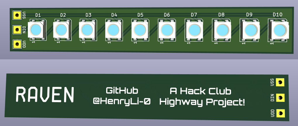
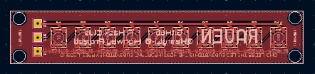
Raven
Note: This is the accumulated (and condensed) version of the documenting and logging I typically do! Check out the repository for more organized files and full logs!
Stats
Total Design Time Spent: 105 hrs!
Total Order Time Spent:
Total Build Time Spent:
Total Time Spent:
Total Build Cost:
06-24-2025: Day 0: Or Day One? Who knows!
Setup!
Nothing much today, just simple repository setup and a silly idea! In fact, the silly idea came a bit before and is a little fleshed out, but it's time to actually start progress on this!
Time Spent: 0.5 hrs
06-25-2025: Day 1: The Idea! On paper!
So what's this raven thing? Is it like some bird...?
anyways, raven! what is it? well basically...
imagine 49 LEDs, or 50. now, imagine it spinning. like really fast. what does that do? it lets us flash sections of the room with specfic light patterns, so that we can color
parts of the room different colors! imagine the left side of a room red, and the right side blue. but we need accurate measurements of the position, don't we? yes, but an encoders and beambreaks are too expensive, for the price we're aiming for! instead, we'll detect the peak (or rising, who knows, thats for the future programming me to fix) of the sensor, then measure RPM that way! we can model and predict the future RPM, then sequence the LEDs to flash a pattern when it is thinks it's at the right position! The code should be able to run really fast, which should allow for accurate timings!
(yes, i spent quite a while debating with omniscient chatbots about the best way to approach this and it's pretty satisfied with this idea!)
And yeah, that allows for super cool lights! see ya next time!
Time Spent: 1 hrs
06-26-2025: Day 2: The Refined Idea!
Tests! As in, not exams!
ok, so we're back! so, did a couple tests today...
Test 1!
firstly (sorry, this first one has no pictures), how fast do the LEDs have to flash before I can't see them changing? Turns out, around a wait time of 0.01 seconds was roughly the point where the colors seemed to start to seamlessly merge! Here's the example code:
import board
import neopixel
import time

led = board.D6
pixels = neopixel.NeoPixel(led, 9)
buffer = lambda ie: [ie for i in range(9)]

t = 0
while True:
    pixels[:] = buffer((255,0,0)) if t % 2 == 0 else buffer((0,0,255))
    t += 1
    time.sleep(0.01)
and after tuning the last line, we start to see purple! of course, the LEDs are still flashing the correct colors, as can be told by the fact that they are always red or blue when it pauses
when you save firmware onto it. this means that, neopixels can, in fact, blend colors through pulsing colors faster than human detection! of course, we can't exactly test how fast they can update, but i do have an idea for later.
Test 2!
but now, a problem seems apparent. since we're spinning it round and round, for a certain period of time, one side does not recieve any light. basically, it acts sort of like PWM (you know, pulse width modulation), a strategy where flickering
a device (such as an LED) is used to safely create an effect of percentage (so a half bright LED is powered 50% of the time). search it up, it'll explain better!
simply, we have to look at the effects of reduced light on the total brightness! of course, there is obviously an effect, but here's a comparison (LED flickering at max speed)
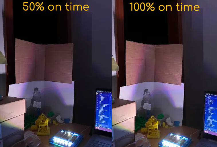
no difference? try looking at the top right of each photo! the camera seems to catch the right photo with a bit more light! simply, the effect in person wasn't too much, it was noticably dimmer, but this shouldnt be an issue once we have nearly x5 the LEDs we currently have (49 outwards LEDs is crazy!)
and yeah, so interesting tests today! i'll be pretty busy tomorrow, but the plan is to find specifics (motor power, good motor speeds, battery stuff, etc.)! also, yes, i used my hackpad for this! ok, that's all for today, good night!
Time Spent: 2 hrs
06-27-2025: Day 3: Really Refining The Idea!
What in the chemistry?
so i havent check the slack in a while, an i really want to do the poster thing (looks pretty cool!), so we need to get this in by 6/29/2025, or at least the poster, to my understanding. ok, so whats on the todo list?
- parts and materials
- motors
- batteries
- placement
- LED PCB
- weight distribution (and ability to tune it in the future)
- safety shell (since, its kinda spinning really fast)
- firmware
- timing and stuff
- calculations for light flow
- figure out bluetooth stuff
- editor
- figure out how to make this easily editable
- might use a text file (probably shouldnt make a tape clone for this)
- figure out how to store this data (and load it onto the microcontroller)
- figure out how to make this easily editable
so yeah, lots of things to do! in like, three days!
yeah so now its 10:30 PM at night and i havent done like anything, so i guess time to turn on some music and start hackin! (had to take a blood test thing today, flowed much better than last year! anyways, back to this!)
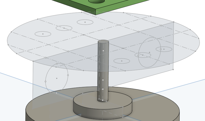
- the diameter (and display ig)
- in order to have a spinning wheel of
deathLEDs be effective in actually showing light in sections of the room, we have to take into account the size of the LEDpanel
(like, the physical dimensions of the LED matrix)! - for the rest of this point, ill take about the diameter, NOT the radius!
- $>30 cm$ is a little sus, since at that point it could get hard to control, as it seems a little large for a small motor to handle. additionally, that's like... the size of like a large plate. like its kinda big.
- $<15 cm$ might be a bit tiny, which would make attaching our panel a little silly (and we need to make a case anyways, so it wouldnt really work?)
- but first, we need to note the PCB? since, of course, the necessary raidus really depends on the distance between the LEDs and thus the size of the PCB!
- neopixels have a $120\degree$ beam angle, which is kinda really wide for our purposes (tons of overlap between LEDs!)
- this means that things WILL blend, which is really bad for our purposes (we want to be able to cleanly split sections of the room!)
- ideally, we need the LEDs to have like $10\degree$ of spread, or less, which means we probably need to do something with lenses, cones, and walls
- so, how? probably block walls on the side that slope inwards. but wastes tons of light! so next idea...
- TALL PCB! instead of a 7x7 matrix, a 2x25 matrix with this inwards slope would be MUCH better, as it's way less obstructive. but unfortunately, thats TALL. like, if we smack each LED next to each other, each one is like 0.5cm, thats 25 cm tall, which would be really not compact
- it would be way better to split it into 5 pcb, so its portable, and we also utilize all the PCBs JLCPCB sends over, so we're also not wasting things! that makes it roughly 5-7cm per side! it also lets us increase exposure time for each side, so the lighting should be the same! (less lights, but more times exposed per revolution)
- so whats the PCB size? dunno. like 1 cm wide per segment, with walls that can be tuned in the future!
- so, in conclusion, i have no clue. through some experiments involving using a single LED on my hackpad to see the effects (sorry no pictures, i was kinda using both hands at once), it seems that this angle for the walls probably will have to be tuned in the future!
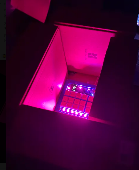
- just played around surrounding my macropad with filament boxes and learned this: light likes to spread. like alot. at least when it coems to these LEDs. (see photo below!)
- so what did we determine? nothing, but we learned a lot! so for now, roughly $25 cm$ seems like a reasonable diameter, so let's stick with that until we get more things understood!
- in order to have a spinning wheel of
balance
- the LED PCB will have to be balanced, but the heaviest thing (other than the motor likely), are the batteries! we aim for wireless, since we cant exactly tether it when its spinning really fast. well, you could use a slip ring, but thats not exactly inside budget.
positioning
- we plan on using a hall effect sensor for stuff, since we're going fast enough anyways! additionally, its cheap! since we're assuming a $25 cm$ diameter, we should use some wires to connect it to a placement near the center. this is because we REALLY want to clear out the noise that could occur when its near stuff!
- since we're using bluetooth, is making the microcontroller spin gonna cause issues? in theory... no? but we'll try to keep it close to the center of the PCB, of course only to a certain extent!
- of course motor in the center, battery to offset weight, the COG near the center bottom
- we'll have locations where we can attach weights (sand ig? or like liquid glue? idk) and tune our system!
- to figure anything else out, WE NEED PARTS!!!
for the safety shell, say hello to my buddy plastic wrap(this is for future concern!)
code
- firmware and control algorithms should be hopefully written tomorrow?
- editor is kinda a future thing at this point, since its kinda a LOT, and kinda depends on how the system acts! (after microcontroller firmware)
conclusion
- we need part specifics!
- we need a design!
- we need code!
so, narrowed down our focus today, so we'll hopefully get things up and running tomorrow! first will be PCB design! here's my plan for BOM
| Item | Price (USD) |
|---|---|
| Microcontroller | $ 5 - 7 |
| Motor | $10 - 15 |
| PCBs (both) | $ 8 - 12 |
| LEDs (all) | $ 3 - 5 |
| Sensors/Wires | $ 2 - 5 |
| Printed Parts | $ 0 - 0 |
| Shell |
$ 0 - 0 |
| Total | $28 - 44 |
so, we should be able to stay within our budget! of course, those $6 might be used in random stuff as we flesh out our exact parts, but thats decent headroom! Turns out... I already have an idea for the microcontroller!
The seeedstudio XIAO ESP32-C3, including bluetooth and wifi capabilities, with other specs being actually kinda bettter than the XIAO RP2040! best yet, its only $5, within the budget!
before i look at a bunch of memes before sleeping tonight, ill do some research with motors! ideally, pretty light, can achieve 1k-3k RPM, (so like 16-50 rotations per second)! of course, we should aim to make the spinning part as light as possible, but we'll see! ok, see ya tomorrow! good night! (also, i wanna draw some art for this release... might not come out in time, who knows!)
Time Spent: 2.5 hrs
06-28-2025: Day 4: Parts Finding and Start PCB!
Pathfinding? FRC Reference?
back again! its 3 PM on saturday! first thing: part search! we need:
- Microcontroller
- LEDs
- Battery stuff
- Battery itself
- Charging bits
- Buck convertors or anything
- Motor
- Materials (for parts and stuff)
- Hall Effect Sensor
- (and magnet!)
- Jumper Wires
also, not related, but new ivycomb album!!!!! anyways, im gonna listen to it in the background while searching for parts! (so far, sounding really good!)
after reviewing the project guidelines, i think this could really be a 6 point project, with up to $150 in funding, but i'll realistically aim to keep it less than $50 (or $100) if i can, since if i break any parts, i should be able to get them myself without going too broke! realistically, shipping may cause us to poke a little bit above (ahem ahem, certain person, ahem), but yeah
- Microcontroller:
- SeeedStudio XIAO ESP32-C3: as said yesterday, fills features nicely!
- SeeedStudio: yippee
- Firmware: circuitpython is amazing!
- SeeedStudio XIAO ESP32-C3: as said yesterday, fills features nicely!
- LEDs
- WS2812B (Neopixels): classic led, pretty efficient (60 mA draw, worse case (20 mA is more realistic))
- Digikey: aint no way that 50 neopixels are $34
- AliExpress: wow they sell individual leds? gotta do a little background check first
- sketchy, might need to buy an LED strip and just steal the neopixels from there
- WS2812B (Neopixels): classic led, pretty efficient (60 mA draw, worse case (20 mA is more realistic))
- Battery Itself
- Samsung INR18650-25R: seems to be good, hold charge for a while
- im trying not to get scammed by some sketchy companies
- IMR Batteries: seems legit from what ive seen?
- Samsung INR18650-25R: seems to be good, hold charge for a while
- Charging Module
- TP4056 (with safety)
- AliExpress: seems pretty trustworthy (choose type c!) (mfw lead warning)
- i think that ones protected? nearly got one that was unprotected
- TP4056 (with safety)
- Buck convertor
- MT3608
- AliExpress: looks good (probably best to use the welcome deal and stuff, might be more worth it to get 3 instead of 2 pieces)
- need to look into this! not exactly sure how they allow the user to change voltages?
- MT3608
- Motor
- 775 motor
- was gonna buy from vex robotics but shipping is atrocious
- Amazon: pwease gimme ur amazon pwime account
- 775 motor
- Transistor/MOSFET
- STP55NF06L
- alright
- DigiKey: shipping might be scary
- STP55NF06L
- Materials
- Likely PLA from my 3D printer (thanks arcade!) for a majority of structural parts!
- Likely need a couple screws (maybe nuts?) to screw it into the structure
- Hall Effect Sensor
- A3144
- AliExpress: its called A3144E but seems to be ok
- A3144
- Magnet
- some random small neodymium disc magnet (all mine have like chipped into pieces)
- AliExpress: i dont need 50 pieces, i need like one or two!
- some random small neodymium disc magnet (all mine have like chipped into pieces)
- Jumper Wires
- realistically, cheapest one that rated nicely would probably work
- AliExpress: eh
- realistically, cheapest one that rated nicely would probably work
hey, so ive been doing some thinking... it might actually be smarter to split the systems and have two systems thats powered by the xiao! let me break it down! the original idea was this: single battery, powers everything. but this is kinda bad, since we only have a single battery (the tp4056 doesnt really get charging multiple at once, or at least in a safe way, as far as i know). this means low battery life, and possible struggles in keeping things spinning. additionally, brownouts would affect the ENTIRE system. the new idea is to have two systems, each with its own battery (and therefore charging module). one is solely dedicated to the motor, and one is dedicated to the logic and LEDs. this makes sure that any brownouts (battery running low or anything) would be isolated. the xiao will control some transistor/MOSFET on the motor side, which will command the motor to spin or not! (this does mean the GND on both sides need to be connected at some point, probably by connecting the BAT- of both TP4056)
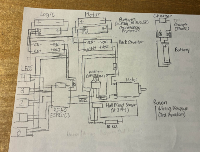
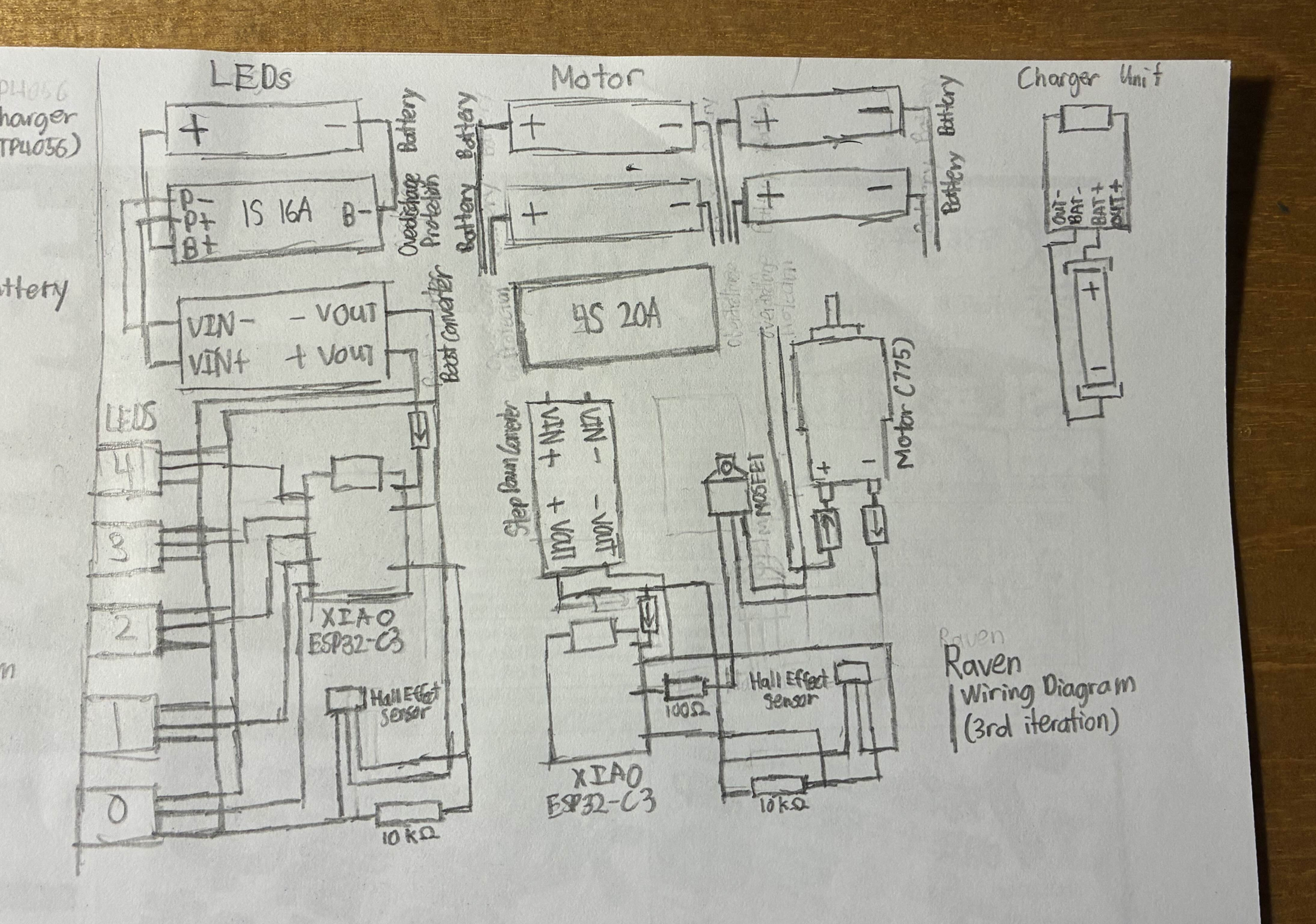
woo, that was some typing! somehow part searching took three and a quarter hours of hunting on aliexpress and across the internet! gonna quickly sketch a wiring diagram (of course, not with the actual electronics symbols, but you get it)
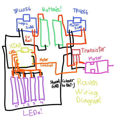
ok, time to start making the circuit! (that drawing took like twenty minutes!)
suprise suprise, i need to find footprints and symbols for like everything!
ok, just found the ones for the XIAO ESP32-C3, just need to find how to install them... wow, success!
huge thanks to https://github.com/ccadic/TP4056-18650 for the TP4056 footprints!
ok, still working on the PCB, hopefully gonna finish it tomorrow! got lots of research done today, just lots of designing tomorrow! ok good night
Time Spent: 4.75 hrs
06-29-2025: Day 5: PCB Work!
Does the P stand for pain?
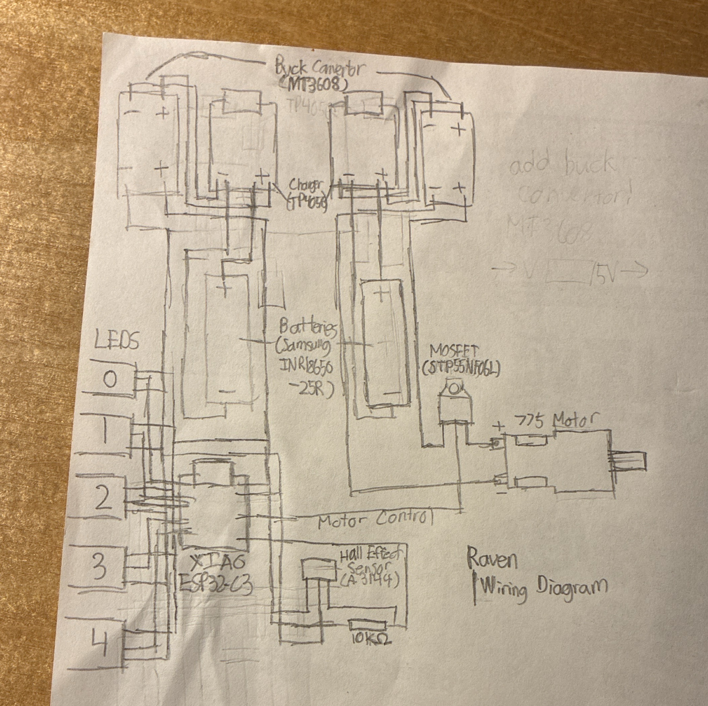
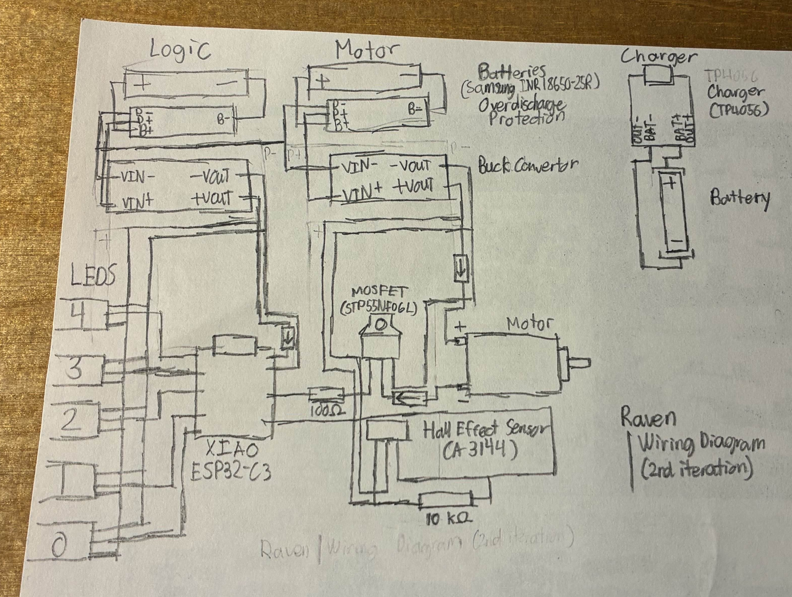
ok, so last night, before i went to sleep (at 4:15 AM, help my sleep schedule is progressively getting worse and worse), i remembered that i forgot to model the buck convertors in the wiring diagram! here's the updated thing (on paper this time though)
so, PCB time! currently a little after 3 PM right now! (also, just realized, how am i gonna solder this???)
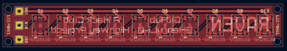
ok, update! i might actually change it to 5 panels with 10 LEDs each! (turns out, i dont think i can easily solder a 2x5 panel without absolutely messing up (since i dont have a reflow plate thing), so ill do 1x10)
so i dont think i can solder 2 mm preceision... ok 5mm might work
ok, 4:12 PM now, i think the LED panel's good!
(yes, i finally figured out how to make the holes that you can solder things through!)
oh wait i forgot to add mounting holes (M2, 2.2mm holes???)
also, just did some research, jumper wires probably arent the best idea for the LED power... just updated yesterday's list of parts! 20 AWG seems to work for power things (and data lines too), so should be good! anyways, just bumped up the track widths of the LED panel, since those skinny 0.2mm are NOT gonna handle like up to 3V, so yeah!
why does it look like a stick of ram
anyways, gonna quickly commit now! (its 4:53 PM!) next stop... the core PCB! (yeah idk what to call it)
ok its now 6:00 PM and i got distracted by a card trick (oops), so back to PCB work!
ok found some resistors: from aliexpress
need a 10kΩ (heh alt code is Alt+234) and a 100Ω resistor! (aliexpress please stop shipping me twenty, i only need one)
found some beefy diodes (to protect motor from backpowering or anything) from aliexpress (this gives me all of them, including the normal diodes)
ok, its 7:18 now, heading off for dinner! oh wow its now 8:18 PM, turns out dinner was exactly one hour?
why does the STP55NF06L footprint or something keep crashing kicad.
ok i fixed the issue, but this first iteration of the core PCB looks super uhhh... ugly. it also has very bad wiring, so im gonna actually redo it!
ok, so i dont think im finishing by 12:00, which means no poster D:
however, the core PCB still looks very sad. still working on it! ok quick update, its 11:36 PM, and im enduring the pain of making a whole bunch of traces. turns out, this PCB isn't the friendliest to do this stuff.
ok, its 12:40 AM now, haven't super checked over the wiring, but DRC thinks its ok, gonna quickly run it by omniscient ai to see what it thinks! ok, its 1:03 AM now, and things look good! gonna add some vanity, then start preparing to CAD tomorrow!
ok, 1:26 AM, think its pretty good!
i added some text wrapped around the center spinning circle! hopefully it turns into a blur when spinning, sort of like a CD! (huge shoutout to Krita for doing this! put the text in krita, used some tool, wrapped it around, then imported it into KiCAD as a footprint with the image converter!)
anyways, that's basically it for me tonight! today was quite the day (tons of PCB design pain), CAD should be just as painful ok, so that's tomorrow! i do need to start planning out the rest of summer, since we only have like 12 days until undercity! (i very likely wont go, since no way parts arrive on time, but we'll see)
oh right, gerbers! ill quickly commit first! (oh its 1:31 AM already? interesting) ok, committed, gerber files made! JLCPCB currently says it'll be around $4.20 (or $6.20? can't really tell if that 10cm x 10cm deal stays?), but shipping is like $3 or something
however, we're still staying on budget! (technically we can go a little above $50, since this kinda is a $150 project, but yeah, staying cheap is probably the best long term)
so, we just need to write firmware, and then somehow find 50 LEDs (we might have to rob a LED strip...)
ok, good night! (i'll calculate the hours tomorrow i guess)
Time Spent: 7.75 hrs (wait no way, like the motor?)
06-30-2025: Day 6: Starting CAD Stuff!
no way, onshape appearance?
ok, nearing a week soon! today's CAD day! or more like tomorrow, since its actually 2 AM on 6/30/2025, and i just pushed the commit with the 6/29/2025 log (im a little too excited to work on this)
but since that's cad day, im actually gonna work on some of the firmware now! ok so its 2:37 AM now, and i got the theoretical settings and startup done, so now all the logic (predictive RPM and timing) needs to be done. gotta search this up, but hopefully it has decimal time tracking (as in, time.time() returns a decimal), since if it only returned whole numbers, that would make things a little less accurate!
ok, good night, see you tomorrow morning! (cad cad cad)
ok its 4:07 PM now, time to start CADing! gonna quickly export the kicad files into stl...
ok, everything imported (except that motor... do i just go hunting on aliexpress again?), lets get the CAD started! (its 4:25 PM now!) i guess we do a mastersketch (DDS noises (FRC reference))
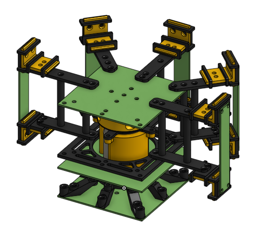
ok so we need something heavy to keep the whole thing down and not take off, so i guess we just make the top as light as possible (pocketing time) and the bottom have attachemts to put something like a weight on (or just make it heavy in general)
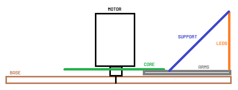
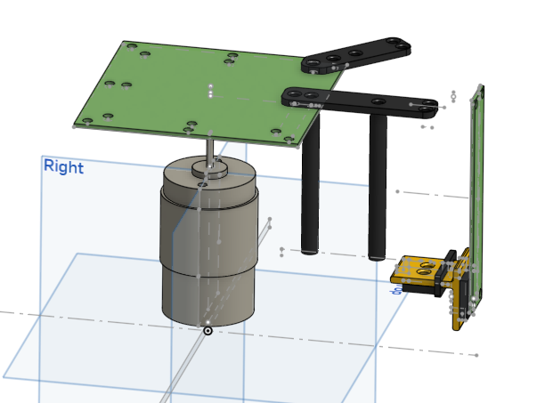
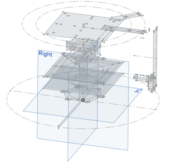
also turns out im actually designed it for M4 screws??? ok, wait, let me just take a break and think about this, since this CAD is not going the way i want it. what we want is a setup that looks like this:
and top down, something like (ok left at 5:05 PM and back at 11:20 PM!) (so uh kinda 6 hours passed and oopsie)
ignoring the fact that they are very not to scale, that's the general idea we're going for! gonna quickly take a visit to the bathroom, then we continue the CAD!
ok i need to figure out what motor im using, since i dont think using amazon shipping is gonna give the best prices (but, i really need to be careful of getting scammed on aliexpress lol) (mfw i say that and the second option is 3 motors prices at $0.99)
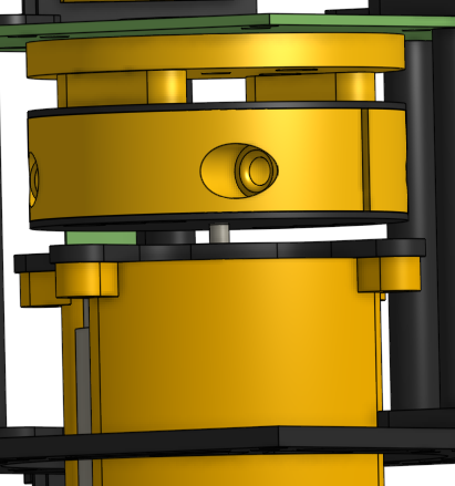
ok, so we need a shaft that isnt a perfect cylinder, or else we will not be able to get a grip... ok, so i actually cant find any non-sketchy D-shaft 775 motor, so i guess im gonna use this one that has a circular shaft, so ill probably use some hub or something (or just use superglue? idk)
hey, add M4 screws (M4, 20mm) to the BOM! and these brass heat inserts (M4, OD 6mm, length 5mm) while youre at it! and these M4 nuts (M4)! (ill have to look into this, but i could use the heat inserts as nuts... might be a bad idea, but ill look into it)
ok, gotta go to sleep now (its so early), but i do have a meeting tomorrow that i'll definitely not use to work on the CAD... no no, that would be such a terrible idea... who would ever do such thing? (subtle foreshadowing)
ok, just realized that the motor has some threaded m4 holes already! gotta update the PCB now, but heres the CAD so far!
ok good night now! (oops got caught being up at 12:40 AM oops)
Time Spent: 2.5 hrs
07-01-2025: Day 7: Updating PCB and CAD Work!
While being very eepy.
yeah i really need to stop sleeping on this cad
9:45 PM here on the first day of july, i guess lets start it off on a good step! just kidding, i fell asleep on the bed and now its 10:58 PM. oops. ok, back to CADing!
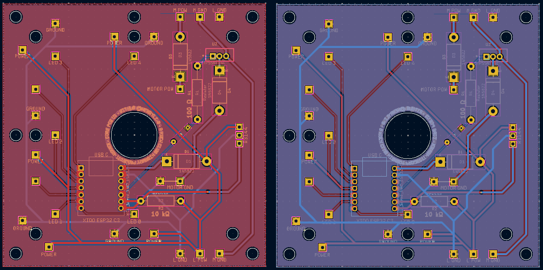
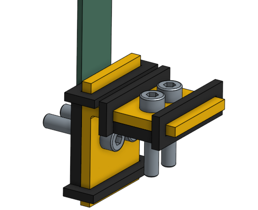
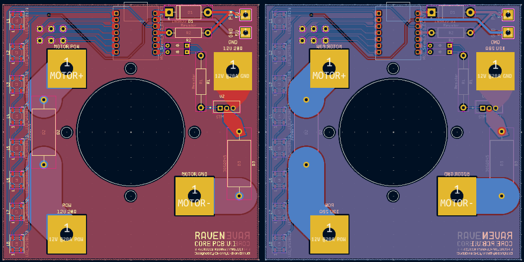
ok, so i gotta update the PCB for this, but the LED panel should be using the M4 not the M2 screws... gonna do that right now! additionally, the core PCB need motor mounting holes! ok, 11:48 PM, and just updated the core PCB! the back now has the silkscreen labels for what each hole does, and shifted stuff so that its farther from the motor hole! (we dont want shorts or funny drilling activity near the center)
ok, idk what took so long, buts its now 12:13 AM, but the PCBs are updated! here's some screenshots!
ok, ill see you in the morning where i should hopefully finish the cad (yes, i had a 6.5 hour meeting this morning, unfortunately couldnt CAD during that time)
speaking of the CAD, the base will need to be split, since i cant exactly fit a 24 cm diameter disc on my A1 mini (18cm x 18cm build plate) (i just had a funny idea about printing a 0.1kg part on the school printers (jk im not actually gonna do that, ill probably split the part into eigths and connect it with the M4 screws))
ok, so CAD, firmware, and BOM to do!
ok good night now
Time Spent: 1.5 hrs
07-02-2025: Day 8: More CAD Work!
designing 3d printing mounts to be strong is kinda hard
yeah this CAD really shouldve been done 2 days ago...
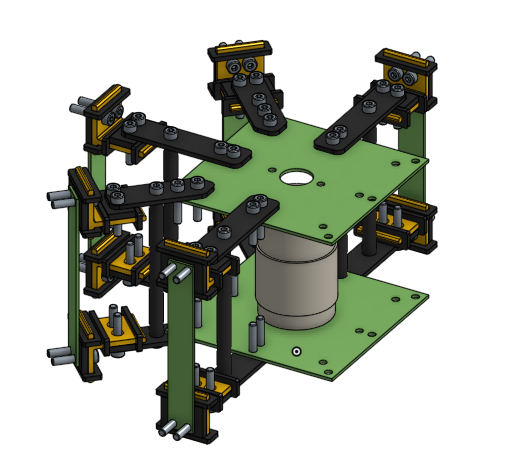
so its now 9:43 PM today (wait this feels a litle familiar), so lets get CADing! i was thinking about moving the PCB wit all the core stuff from the bottom to the top, but throught that this would expose the electronics a bit too much, and it might not have the stability that mounting it directly the the front would give. also, for now, the LED panels also serve as protection from when any electronics in the main board ever flies out (please no). basically, i will need a lot of filament for this one...
i just had an idea, what if we added a thing called a speaker directly into the thing? nah thats actually probably a bad idea if we're using the xiao (since, we dont exactly have lots of extra pins) also, just realized that the way we setup redundancy for the MOSFET and the sensor is probably a bad idea (for the MOSFET, both are set to OUT, meaning we could have issues, gotta add some diodes...) i'll fix that later!
ok just got jumpscared that we might not be able to trigger the STP55NF06L with the XIAO, but after sneaking around the internet, i found a datasheet, and it looks like we'll probably be ok! ok back to cad
ok why did yesterday's windows update steal 21 GB (mfw windows keeps spamming me with updates and install four apps of bloatware on my device including one that probably has some vulnerability that'll show up in like a month that allows it to take over peoples computers) (ok now who used 0.1 GB from the last time i looked at that screen. yeah i see you, 20.6 GB to 20.5 GB...) (WHYS IT AT 20.1 GB NOW) ok im gonna install this update and try to fix my computer
hey peeps at microsoft, small request, please stop filling my computer with random intern slop! i really dont need to be forced to have copilot or whatever this new phone UI next to my start menu is. also, please stop messing around with my desktop icons! thanks. also please give my 20 GB back. thanks! back to CAD...
ok its been 20 minutes and i think i found the issue, hopefully not bad happens when i tell windows to delete previous windows installation data... something funny... the internet just broke. i guess thats the one time onshape isnt the best cad tool! oh nvm its back now
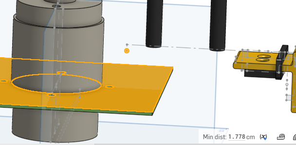
ok so we might need some caster wheels or something for the spinning bits, since idk how a short metal shaft with 0.35 cm of clearance likes having a whole spinning system mounted on top of it, but ill just add spaces to attach on future wheels if necessary (ill probably just make them out of PLA or something)
wait a second we kinda need more clearance
ok more clearance get
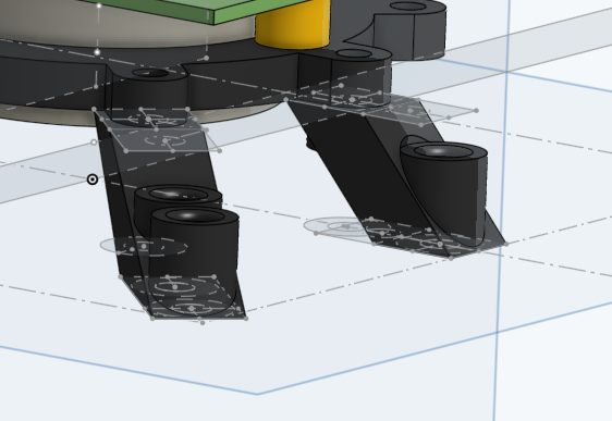
ok so ive been trying to do this CAD in a way that the printed parts dont like snap from centrifigal or whatever force (basically, spin at super speed, outward things fly), so ive had an idea! the PCB is basically solid copper, so we dont have to worry about that too much (yeah, try snapping one in half with your hands (or maybe dont)). its also in the center, so it doesnt experience too much, we just have to make sure we solder our connections well!
so its been like 10 minutes, and i just realized this idea isnt perfect, so im gonna keep paying around with configs
actually yeah, this idea does really work at all, either something can break or something is weirdly/impossibly mounted, ive ran through like 3 configs already
WAIT! THE SOLUTION IS JUST KISS (KEEP IT SIMPLE, SILLY!)! THE SOLUTION IS JUST A BRACKET WITH OPPOSING SUPPORTS THAT HAS SPACERS!
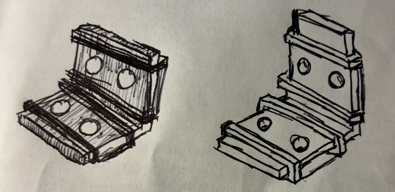
so, what are you even looking at? yeah, probably shouldnt have drawn it with pen, but it was first thing i could grab, so so be it. basically, you can see the bracket there, with the clean surface being the on point bottom right (clean surface, as in, the face that isnt covered with layer lines). then we have these four other caps
that wrap around the bracket, with the clean surface facing up. then, we have a spacer that's just solid PLA that goes on the bases of each screw, with the clean surface being the surface that, when you look at top down, you see the screw hole. then, we can wrap this around the sides, allowing us to make sure the caps
dont move. (we can also just super glue just to be super sure!) and thats the solution! the screws then go in, and it stays! nice! ok, time to CAD this! (wow, that was a lot of thinking...)
yeah i guess i gotta CAD this upside down, we're actually kinda getting really high in the air already...
ok, being forced to go to sleep again (but its only 12:30 AM???), so here's the CAD update!
anyways, that's it! hopefully more progress tomorrow, but yeah, gotta update the PCB too! (maybe i wake up early tomorrow and grind? idk)
Time Spent: 2.75 hrs
07-03-2025: Day 9: Even More CAD Work!
cad cad cad
henry did not wake up early.
oh wait i just realized todays the first day of a certain convention in pittsburg! guess ill see a couple videos coming out in a couple days... NO WAY! ITS WATER THEMED! (water game?) (scroll to the bottom)
anyways, its 9:02 PM (this feels a bit way too familiar...) and its now CAD time! also, i just remembered LCSC was a thing, and since desoldering LEDs off an LED strip (where, the LEDs could have a strong adhesive, LEDs could be sketchy, i could melt one again, etc.) is a bad idea, LCSC probably is a smarter idea (for a lot of our electronics, in fact) (might be a bit more expensive, but honestly cheaper and more reliable in the long run, just need to make sense of these aprt nubmers...)
anyways, back to the CAD! (reminder for myself that i also need to update the PCB with some diodes)
but yeah, something like that! probably should make the bottom a bit shorter though... ok, done! (parametric cad!!!)
hmm, someones (probably me) is gonna get punched real hard by these two protruding screws, might make a big fat long spacer in the back (maybe not too much of a problem, but we'll see later) also, the nuts might touch the power and ground of the LED panels, so we need to take note of that
ok, currently simulating the load and stuff, had to replace the LED and PCB material with plantinum because FR-4 doesnt have some ratio or constant or something so onshape cant simulate it
oh wow whys it taking so long... is onshape like doing a blender render or something
oh its done! took like 7 minutes, but its ready! oops i did a modal simulation instead of linear static... guess its another wait? oh wow, much faster! wait a second why does that look so sus
ok, putting 2 pounds of force is unrealistic, but its not gonna do it any good. anyways, heres a more realistic 0.2 pound load on it
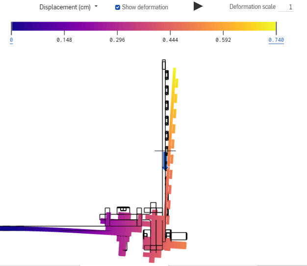
in the end, the top structure would probably keep it all together! ill probably just keep onshape on overnight and simulate when the cad is actually done! right, back to cad!
just had an idea, what if we make our base heavier by just filling it with sand? it would make it essentially heavier than 100% infill PLA, and it would probably be way cheaper? wait a second i dont even need to buy it, i have a beach like a kinda far away (maybe gravel will also do?)
ok, silly CAD activities, this might be the worst quality CAD i made in a while, but ill clean it up in a bit
i just remembered that we need to do the light thingy (you know, the thing where we decrease the angle of exiting light?)
wait we might actually need all the screws they give (so far using like 75 screws) this reminds me of that one time we spammed rivets on one robot cad
ok, gonna go to sleep now, here's the current state of the CAD! i guess ill use the extra screw space on the LED pannels to screw on the light blocking thingy, and yeah, we're getting there! still lots of other things to do (PCB update and code and BOM), but we're getting there!
ok, good night!
Time Spent: 3.5 hrs
07-04-2025: Day 10: PCB and Electronics
pcb funny, and electronics too
ok, starting today at 2:20 PM instead of the previous couple days! fist things first, im gonna update the PCBs!
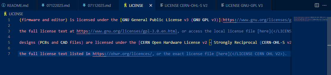
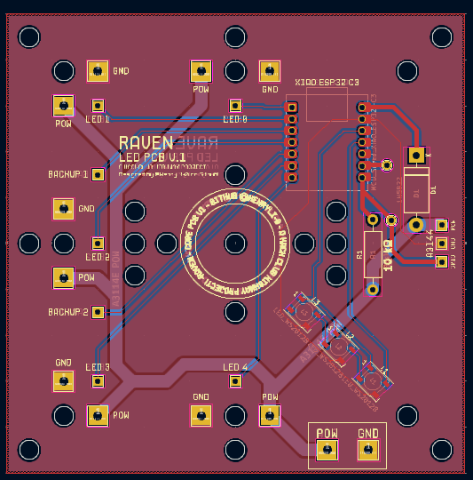
ok, been doing some work, then just remembered that i needed to update the license (since, GNU GPL v3 is kinda a more software thing). just updated it, with CERN-OHL-S v2 for the hardware and GNU GPL v3 for the software! that should keep everything open source! ok, quick commit, PCB work is still being done!
ok, board should be ready!
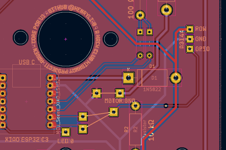
ok, kicad wont stop telling me in DRC that theres errors, since the A3144E GPIO isn't connected (since, connecting both GPIO to listen to the A3144 would probably end badly). im gonna have to write this down somewhere, but we have to connect those two pins!
ok, we need to update the LED ones now...
also, dont remembered if i mentioned this, but the LED panel needs updates because... a nut kinda crushes one of the LEDs, and the bottom ones might be a little too close to the pads (ill do the LCSC stuff later)
wait its 3:45 PM now, im gonna take a quick break... back at 4:04 PM! (not found)
since the LED panel is 99.8827mm tall, we're getting really close to the 10cm mark, so we might actually have to make the RAM stick LED panel a bit wider, which should, in theory, not really change the price? this quote is taking a while... yeah, still $2.10! ok gonna work on it...
LED PCB now updated! updating the cad now...
ok, exported, importing into onshape! (also, quick commit)
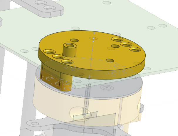
uh why is the xiao made of solid gold now (yes, i know that its just the color, but it looked really funny)
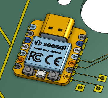
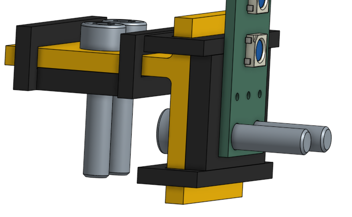
wait i might actually need to revisit the idea of putting the boards electronics on top since... er...
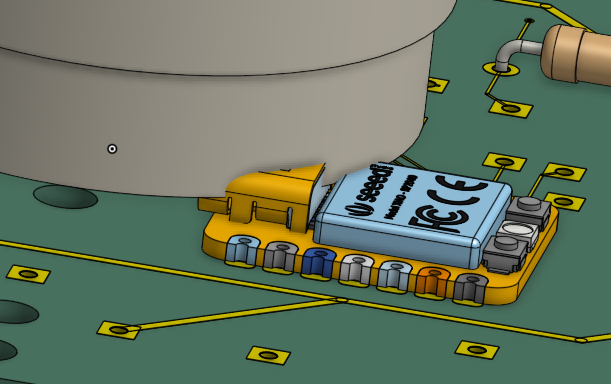
yeah we might have a bit of a problem... yeah, mounting it on top might be the move... also, we have a LOT of collision issues
so we might have to solder the wires upside down for the main part, which is probably a smart move if we incorporate a couple zip ties, since that should keep all the wiring safe and tucked inside the machine (we dont want a flying whip of sorts) we also need to have a safety off switch, which i kinda forgot to add to the BOM, but that'll probably be ziptied somewhere too
played around with how wire length can impact singal strength, and it seems that sus wiring that goes back and forth for very long doesnt mess with the signals too much, we'll have to see with the neopixels (right now, its just GPIO value determines on/off, unlike neopixels that have to send the info)
ok, its 5:06 PM and im gonna be back in a bit! as for CAD work, planning on starting to do the right side (with the batteries and chargers) now!
ok, back at work at 8:15 PM, and did a bit more playing around with those LEDs...
basically, doubled or tripled the amount of wires going back and forth, so this is like seriously an overestimate of what the actual leds will experience, but theres no really difference in brightness, so i think we're ok! gonna write a letter real quick, currently 8:45 PM!
ok so now its 10:33 PM, and the neighbors somewhere are really playing around with fireworks, or at least someone in like a 1 mile radius is. anyways, since it sounds like something more violent, im gonna try to focus (while im like the closest to the window)
whys the floor shaking
hey so im back, thinking about it, is a 775 overkill for our system? given the battery, TP4056 output, and converting it to 5V, we might have like, very little amps to deal with for the motor, which might just not spin. basically, we dont need industrial motors, just motors than can spin the roughly 2 (lets say 3 for headroom) pound thing at 1k or 2k RPM, gonna do some research now...
wheres the search bar in here rdfjpasdjvksdnfaksdfasdfas found a good RS550 motor, except for the fact that it leads me to whatever dollar express is and THERES NO SEARCH BAR ADKLASKLDFALSKDJ (i dont need a usb air humidifier, i just want my motor)
yeah so its now 11:50 PM, and im still trying to research what motors work and dont, and if my wiring idea sucks, since research really conflicts with itself. im looking at TP4056 wiring on youtube, and 3 of Orbit (FRC 1690)'s videos show up in a row in Explore More
(2022-2024).
ok, so we've had some changes! instead of running everything through the TP4056 modules to control the voltage and what not, we're actually gonna use the battery directly connect to the MT3608 to get power to the logic circuit, then we have some other convertor for the motor, which also has battery directly, basically we dont have the TP4056 on the spinning bit itself, but just the batteries. then connect it to the ground of the MOSFET, since we need to do the whole electron thing
ok, so its 12:40 AM now, and ive been doing a ton of researching and might need to make a ton of changes. basically, today was very confusing, and i really need to rethink the power system. kinda tired, hopefully waking up at a reasonable time tomorrow!
ok good night
Time Spent: 4.75 hrs
07-05-2025: Day 11: Further Confusion
electronics are confusing
ok, first things first. electronics.
4:36 PM right now, gonna search in the depths of youtube videos to find any wiring example with the battery!
yeah so im kinda super confused right now. so ignore what i said last night, we should definitely not connect the raw battery straight to the circuit (we need overdischarge protection). so, apparently the TP4056 does and does not have overdischarge protection? video and research is conflicting, but im gonna assume not. a battery management systems is kinda a bit up there in pricing, so im gonna research overdischarge protection now
oh its 5PM theres some mosim announcement stream right now, guess ill leave the 5 minutes youtube premiere timer in the background?
ok, turns out i forgot we had discharge protection oops
ok so that was 5:30 PM, organized my stuff, did a little art for the preview image (does that count for time? i guess not...), so here's the idea! basically, we charge the batteries serperately, then plug it into the machine, where we will NOT BE CONNECTING IT RAW, but instead, have an over-discharge module (that im still trying to find :D), which should give us a ton of amps! also, this means that we need big fat beefy traces all over the place (since, 20A max discharge rate is kinda a lot, since we designed with 3A max in mind)
heh i just drew some art (oops its 11:50 PM now) oops now its 12:39 AM, ill continue this on my phone!
ok its 1:36 AM and im on my phone now with github mobile, so dont be expecting any pictures! trying to do some research in the safer metoeds while still getting reasonable power, and i think what we said before (over discharge module thing), is ok! gonna hunt on aliexpress now...
found this over discharge protection module! instructions on how to use it unclear, but another one that looks similar also has instructions so its probably the same right (please be)
yeah i fell asleep typing that, so thats it for 7/5/2025! good night!
Time Spent: 1.5 hrs
07-06-2025: Day 12: Hunting
lcsc watch out WAIT ARE THOSE LEDS
yeah so we kinda gotta finish this...
just did a little research on the reviews of yesterday's overdischarge stuff, and it seems good! only downside is that its a little expensive (dont worry, welcome deal here! not sure how many deals i can get...) so, i guess we need to redraw the wiring diagram! (its 9:30 PM right now) wait a second, why does it say supply voltage 12V to 36V, guess this isnt the product for that!
so we need the entire battery output, but overdischarge protection to stop lower battery sus activity, so the battery should be able to deliver its stated 20A, but not get restrictied by the TP4056's 1A dishcharge thing (which is also one reason we arent including it on the spining bit now)
ok i gotta go for a second (its 10 right now), since my cousin is currently doing something in texas (i have no clue whats going on) ok three minutes later, and i guess they just diappeared off the face of the earth? i dont really know, gonna go back to search on aliexpress and LCSC, oh looks like theyre back
also the MT3608 that we had earlier does 2A max, which isnt enough... however, heres a battery charger protection thing (choose 2S 20A Balanced)! (uh idk if running this on only one battery would work?) yeah idk if this is the move, its layout looks super cursed, and im not exactly sure buying 4 batteries is the move. looking into making my own overdischarge protection circuit (bad idea), and i see a minecraft comparator reference
theres no way im soldering that
anyways, heres some things i found: - 1S 24A, might be the one! little sus, but should be good - 1S 10A, ok, less sus, but not enough amps! - some 18650 format battery holder of sorts
ok anyways its 11PM and im off to watch frozen 2 for like the fifteenth time ok see ya
ok its 12:13 AM and i just finished reading all the FRC servers im in (lurking behavior), anyways back to aliexpress! the 1S 24A one (the first link) seems pretty ok, a little sketchy (not too many reviews) and one picture has a chip without a part marking in the photo, but reviews seem alright and the pictures. also, just realized, these will take a LONG time to ship. like it says july 19-22. eh, i guess trade off for being so cheap.
ok, so thats good! time to hunt LCSC for an A3144 and the MOSFET
hmm you need to by 5 A3144 at once, but i guess LCSC is better since its like $4 on aliexpress for also 5 (also, LCSC is probably more reputable) here's the link! also, whys the datasheet only in chinese
also, AP scores dont appear out yet? guess ill check in the morning
ok, since the pdf didnt allow copy pasting, i just downloaded it, went to google drive, uploaded it, and now i can copy and paste. yeah it just works like that. anyways, looks good! gonna hunt for the mosfet now, we also need leds...
yep, here's the STP55NF06L, cheaper than digikey!
ok, WS2812B now, shouldnt be too hard... oh yeah, nvm, since theres apparently 46 different ones, guess i spoke too soon... also thats crazy, 983885 and 1010610 leds in stock, how many do they mass produce at once?
waa who makes this many leds? (please send me your secret led stash)
wait i need to find what footprint or at least what the LEDs i have look like... ok, whatever LED_WS2812B_PLCC4_5.0x5.0mm_P3.2mm means (probably 5mm by 5mm base and 3.2mm tall?) reading through this datasheet for these leds and dont really get whats 500 euros?
wait this is funny

anyways, im gonna continue research on the phone, currently 1:02 AM! (lots of things start tomorrow, guess i should try sleeping earlier today? probably not)
Time Spent: 3.5 hrs
07-07-2025: Day 13: More Hunting (and LEDs!)
did someone say leds
yeah its 12:52 PM and im forcrd to touch grass to earn money
turns out the middle achool has the same internet password as the other schools across NYC so it appears that i maybe can hunt for more LCSC parts
yeah so last night i fell asleep (oops) so i guess heres the summary
basically, the one i was looking at had weird funny funny, basically i had no clue what that extra characters on that text mean. also, the marking on the LED itself (like the lines) were different so i went back on LCSC and found this thingy, looks pretty close to the actual thing (i have to make sire the markings match when i get back home), but it has a 5.0mm x 5.4mm, wait nvm actually the base is 5.0mm x 5.0mm, 5.4mm is just counting the pads! ok, this should be the one!
yeah its now 3:14 PM (last thing was from 1:20 ish) getting bored now (we're all done with our stuff), kinda miss my computer right now, but we'll do with what we have.
60 of these LED (same as the ones up there) cost $3.95 (FRC 395? two train robotics?) anyways, within our budget! (wonder what shipping costs are?)
ok, i guess we have to calculate trace width at home (and figure out and finalize the power system), so its 3:18 PM, i need to find the bathroom in this school, so see ya!
yeah bathroom was in a very cursed spot and the bathroom itself was very cursed. anyways, its 9:15 PM at night, and i decided to do a little something for the last 15 minutes!
yeah, i also didnt expect to see the insides of my hackpad tonight, but i just decided to do a little cleaning! while it was out however, i decided to snag some data on its light spread! unfortunately, my measurements tell me that its more than 180 degrees, since it somehow lit areas below the PCB, but that's also probably since we're in a white room with a couple reflective surfaces here and there. anyways, the aforementioned LEDs seem good! anyways, finalizing the power system time!
wait research is telling me we need like 1 or 2 cm thick traces for 5V @20A... anyways, lets ignore that for now, and draw this diagram!
why does going outside make me so tired (i just laid in bed from 9:30 PM to 10 PM) ok now im being forced to sleep, i guess you get a wiring diagram tomorrow? just kidding, took like 45 minutes, but here's the drawing!
ok good night! (yeah i need to update the journal for today and yesterday, ill do it sometime!)
Time Spent: 1.5 hrs
07-08-2025: Day 14: Traces and Confusion
what is going on
no way its taking this long, lets finish this! so, its 6PM right now (started updating the journals at 5:45 PM)! realized that yesterday's diagram isnt super clear (as in, image quality, its a little blurry), so here's a better image!
ok, first thing, lemme double check that the MT3608 can actually support our amperage (and volts too), so lets do some math... ok, so if we can support 3.7-4.2V @20A, we can do 5V @14.8-16.8A, which is ok? also, for the motor, if we need, we can run it at 14V @5.29-6A (lower limit is roughly 5.28571A), which should be able to power the 775 motor? it might actually be ok for this! (we're feeding a total of 74-84W)
ok, just ran through this idea with an omniscient ai, and it says its pretty much ok, just have a shared ground for everything and the buck convertors, so yeah, thats what im gonna do! well, after dinner, its 6:30 right now!
ok, back, its 7:45 PM now! i guess its time to do the PCB stuff? gonna calculate the width of the traces real quick...uh 2.5cm traces is kinda crazy, lemme double check that... uh yeah.
ok, so since we cant have giant fat 2cm traces on our PCB, we're gonna have to do something different. uh. so we kinda need to banish
a couple amps on the logic side... wait a second, does the battery only supply whats needed? oh. oopsie, i guess we dont need 2cm traces on our PCB! (except for the motor...) ok, PCB time now! im gonna estimate the logic line needs 5A at most (probably only 3A at most, realistically, but lets just do 5A to be safe), so, according to kicad, with a current of 5A and temperature rise of 10C, we need 2.76552mm traces (round to 2.8mm, just to be safe). meanwhile, for 20A and temperature rise of 10C, we need 18.7156mm traces (round to 20mm, just to be safe). ok, time to get to work!
hmm... how to change the entire net... did it manually, LED panel's almost good! just gonna change the pad size...
ok, 8:50 PM, led panel done! now for the big PCB... (also those traces are MASSIVE) yeah, we also need to do the thing with the shared ground... yeah so this is kinda confusing... wait im gonna quickly commit the led stuff
oh yeah we should also look to source our diodes from LCSC
ok, back (took a rest from 9PM to 9:30PM), yeah these nets are absolutely messed up... really considering redoing it? how am i supposed to route the pins of the MOSFET when the traces are 2cm thick... yeah so if we shove 20A in a 0.8mm trace, we get some sweet 1800C temperature rise (aka, we start dealing with liquid copper)
ok, you know what, i guess we'll let it rise 15C, and just print some fan blades to stick onto this (since, this thing is essentially a giant fan), bringing out traces to 14.6331mm wide, rounded to 15mm
wait im gonna find the datasheet or data of the motor to find out how many amps we should actually aim for
need to do some math, so if each LED is 5mm apart, and say, a 25cm diamter, we have a roughly 158 LED long circle (assuming the LEDs fit the circle perfectly, which they dont), anyways, what was i calculating again? we need to do a full revolution every refresh
of the eye, so thats like 50 rotations per second? so like 3k rotations per minute?
wait im a little silly. oops. so uh, basically, since we're running it at 14V, we actually ARENT shoving 20A down the line, we actually are doing 5-6A, so we actually only need 4.39879mm traces (calculated for 7A, rounded to 4.4mm). yeah sorry, that was a big waste of time... ok, looking for motors (original one is kinda... lacking documentation), andymark has terrifying shipping prices
wait im actually kinda confused because 14V @5-6A is, in fact, NOT enough for this motor... im gonna stop doing the PCB design for now, gonna focus on what motor we're using. ok, just spent a bit look at some 550 motors and i think they aren't strong enough? i guess we just stick with our original motor and try to figure stuff out?
looking back, a 1S 24A BMS makes kinda no sense for the 20A max discharge battery, gotta fix that too. guess we going for 1S 16A then! ok, talking to omniscient ai, i just got insulted, so i guess 775 isn't the way to go? so the 775 is an inrunner motor but we're looking for an outrunner motor. however, that setup would require us to have a slipring since the mosfet is still in the spinning bit, so thats kinda out of the question. also, the boost convertor does 2A max so we need to find another one
ok so its 12:30 AM right now, and ive think ive accepted the fact that we cant do this do a 775 motor, we have to use an outrunner motor. however, that requires us to move the entire motor control circuitry off the spinning board and onto a new board that stays stationary with respect to the table. this means we have two microcontrollers, one in the spinning bit for LED control and one at the base for motor control. they should communicate when to power on and off via bluetooth!
something something esc, honestly, im a bit too tired tonight, so i guess ill continue looking into this tomorrow!
good night! (12:50 AM woo)
ok so its like 2:31 AM and ive been looking at memes for like an hour (i should stop), but realized im the buggest silly in the seven seas right now. we dont need a drone motor or an outrunner motor. we just need to flip the 775 motor upside down so that the shaft touches the spinny bit and spins with it, and is normally mounted onto the bit that doesnt spin. then, we have to have the two microcontroller setup, but this time we can actually use PWM and our MOSFET idea/setup (instead of a whole ESC setup for drone motors and whatever). this does mean we need like a giant clearance between the motor (like the big part) and the lower PCB, but i guess we could just print the bottom and just have a top PCB if we have to. anyways, this also gives us more space for the motor PCB and its wiring, so thats nice! ok good night!
Time Spent: 4.25 hrs
07-09-2025: Day 15: Boost Convertor
henry didnt find it
wow today was quite the day, its already 10 PM..., anyways watched another movie today, time to start working! yeah so today in the doctors office i got bored while waiting and decided to research a couple of boost convertors (since the current MT3608 we have has a max amp of 2A, which is quite sad when we want to power motors). anyways, found this one, but it requires an input voltage of 10-32V, which the battery doesnt exactly deliver. therefore, we continue hunting.
yeah so its been 22 minutes and im starting to think there arent any boost convertors around for this job. so uh, found this but its limited to 5A in its input, so yeah. im kinda getting desperate here.
ok who keeps breaking the internet router
so i just had an idea, yeah its not gonna work (it was to skip the boost convertor for the motor and just attach it raw, but we need more volts!) yeah its been 45 minutes now and i cant find a good one. ok its now 11:05 PM and im just gonna take a break, ive looked through way too many aliexpress offers today...
ok im back at 12:15 AM and im honestly very tired lol, but lets try to push through.
here's a thing for 2A battery protection (choose 2S 20A Balance or something)
alright, lets just finish this research phase, im getting really tired
what did i just come across
ok theres actually no way i spent the entirety of today search for a single boost converter. anyways, im just gonna draw a wiring diagram real quick (yes for v3)
yeah so i just realized that... this soltuion kinda means that i need a step down to 5V thing for the motor system since we have a XIAO that doesnt want to become a frying pan
yeah ok, laid out all the components, its 1AM now, im just gonna wrap this up tomorrow (yay dont have to go outside tomorrow since its online on thursdays) (probably going to school on friday for driver practice? probably a good idea)
so yeah, thats it, good night!
Time Spent: 2 hrs
07-10-2025: Day 16: Rewiring
batteries
ok, its 4:10 PM, so lets get this done! after yesterday and a bit of research before i went to sleep last night, ive determined that theres like no viable option for a boost convertor that can convert @20A, even at low voltages, to higher voltages, at least, none that are cheap. basically, all the ones that i could find were in the $20 to $30 price range, which is absolutely silly, so ive actually got a better idea! we just, instead of spending so much on a single sad boost convertor, we actually spend it on batteries, so that we already have the correct voltage! (this is also cheaper than buying the boost converter, gives us more power, and also allows us to skip the whole boost converter bit for the motor!)
this means, the motor... gets 4 batteries. yeah. however, note that the boost converter i found was $25-ish, and the 2 additional batteries would only be $10, meaning that buying batteries instead is actually a smarter move! (the omniscient ai also seems to agree, so this is probably also the good move forward!) however, all we need to do is make sure out battery protection system (as in over-discharge protection) is ok and not, you know, super dubious
to the aliexpress! but first, gotta do something else, brb! (its 4:20 right now)
yah so its 12:00 AM and i took some practice test and think i did ok, but anyways, back to drawing the layout! gotta find a 4S battery protection thingy... ok, found one thats 4S but 30A (we need 20A or less), 3S 20A (please so close)
idk, so far found these two but i dont like something about both of them - i cant tell if this acutal does discharge protection since weird docs contradict title but idk - weird connector and hard to read docs
ok, went back to drawing the wiring diagram, but im not sure if we should do two hall effect sensors or one, ill brb, just gonna save and commit and continue on my phone!
how am i on 10%, anyways, basically, heres the deal. we have the two systems seperated (hey maybe we can use some of the extra pins for a speaker), only connected by bluetooth, but what if that connection fails, or we need more accurate data (since, RPM can change very fast). if the hall effect sensor is on the LED section, we wont have the ability to speed up accurately (probably some PID control), as in the feedback data will always be delayed by the connection. this shouldnt be a big deal, but disconnects or signal intereference can mess with this
ok, what if we moved the hall effect sensor to the motor side? well, we wont be able to have the exact timings for the LEDs, which is kinda really bad since the LEDs really need to know where they are. speaking of which, i have an idea for super precise position measuring, and kts very silly. code execution time measuring and prediciting, we havent even started firmware yet...
so basically, have delays and risk bad connection, or just dont even need them to send this data and just give each of them their own. and i think thats the better move since we get 5 of them at a time anyways
ok so im going up to school for driving practice tomorrow so good night! (its 1:24 AM, guess ill do it on like 5 hours of sleep) also, gotta remember to find a stronger boost converter for the LED side, wait, i dont remember saying this, but the logic side has been renamed to the led side! also, subsystem also works in place of side for both of them! ok good night now!
Time Spent: 1.25 hrs
07-11-2025: Day 17: Planning and Electronics
cool leds!
ok its 9:55 PM, and i just finished updating the journal with the last three days! i feel like we're really dragging things out, not intentionally of course, but things really should be faster. looking back, i think a good thing we should do is create a couple goals and deadlines, so that we dont keep going on forever! ideally, it should be 100% complete by 7/15/2025, as far as the digital designs. materials then should come around the end of july, then can be constructed across maybe two days, then finally complete! of course, assuming everything arrives on time...
ok, so here's the deal! - 7/11/2025 - finalize any electronics - start working on the LED subsystem PCB - 7/12/2025 - finish working on the LED subsystem PCB - start working on the motor subsystem PCB - finish working on the motor subsystem PCB - 7/13/2025 - fix any PCB issues - complete BOM list - start finishing the CAD - 7/14/2025 - finish the CAD - prepare for release! - 7/15/2025 - release! - (if you see this on 7/15/2025, i guess henry actually did it on time!)
so yeah, we got a plan, lets (hopefully) do it on time! woah, just got a flashback, wow, i miss hack club's arcade event... dont worry, summer of making is gonna be the next thing i work on after this!
ok, electronics diagram now! its 10:04 PM, and i guess lets aim to be done by 10:15 PM! do i add a speaker now... its 10:20 PM and yeah, drawing these diagrams to look good is pretty hard... yeah we're not adding a speaker, its probably gonna take like two more days to research it? need some amplifier or something
ok, its 10:29 PM, and i thinkk its ok! the only issue is that we dont exactly have a 4S 20A over discharge protection module thing, so we cant exactly connect that, but we'll do that later! ok, picutre incoming any second now...
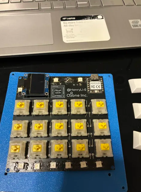
yeah, so we gotta go fast, before i start to grind on mosim, speaking of which, heres why LEDs are great!
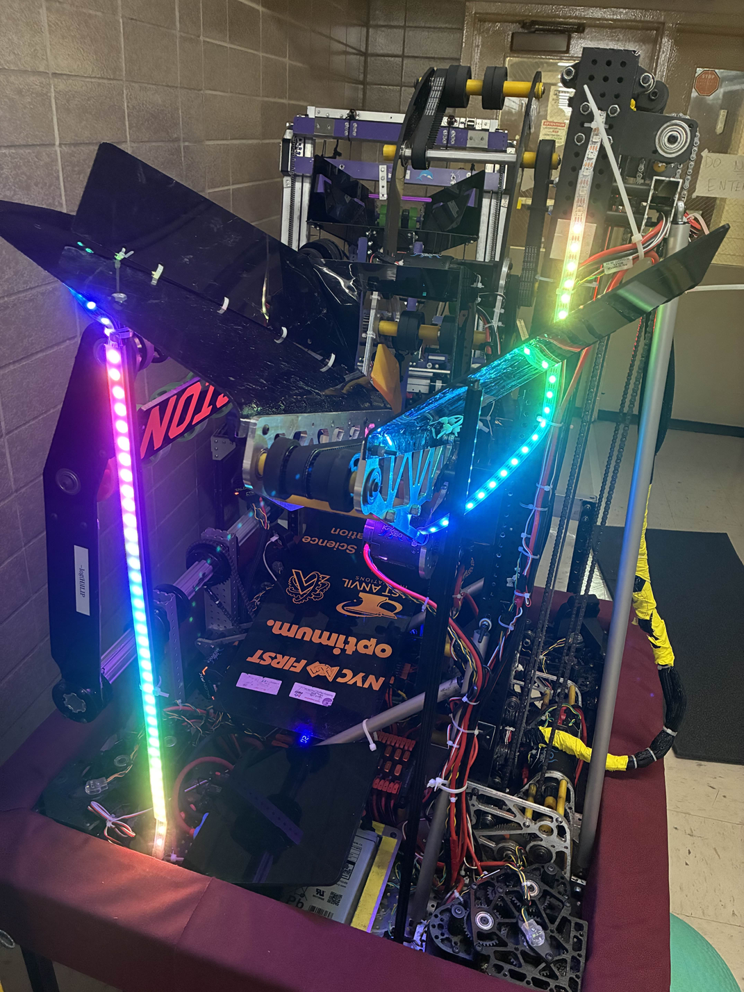
yep, we got some drive team practice today! also got the robot up and running again, so that nice! anyways, LOOK AT THOSE LEDS! LOOK AT THAT GLOW! (why are there like 5 or 6 LEDs off at the end... probably a code thing) anyways, back to the PCB! yeah i guess we just keep the core PCB around for now for reference! ok, quick commit!
no way, kicad is on v9.0.3 already? im still on kicad v8.0.8... have i been putting off updates that long? i guess ill update after finishing this project! anyways, back to PCB-ing? CADing? PCBing? idk (PC Bing? like, a search engine on a personal computer?)
why does the internet randomly implode wait, its like 10:40 PM right now, imma brb!
yeah i got distracted by mosim oopsie, its 12:01 PM now...
ok, just finished making the schematics for both of them! gonna start working on the actual PCB tomorrow! (can we do a record of two PCBs in one day? who knows...)
so yeah, pretty short day today, hopefully can spend the entirety of tomorrow on this! ok, good night!
Time Spent: 0.75 hrs
07-12-2025: Day 18: Firmware Ideas and PCBs
no way is that code?
ok, so its 4:00 PM now, yes i woke up at 1:00 PM, i had like the most insane dream
anyways, last night, spent a couple minutes (like 15-ish?) thinking up of how we should do the programming side of things (which i seem to have forgot to include inside the schedule plan?) control wise I think I got it, PID and getting interval timings based on code execution time compared with the internal clock synced with the device. basically/specifically, im wondering about how we would represent LED patterns in the instructions so that it runs any combination we like
so a light value
can be represented by 5 numbers: the individual RGB values, start angle, ending angle! 0 degrees could be wherever the magnet is for the hall effect sensor (since, its a good reference point for the LED logic itself and for us). but how would someone represent a light moving to the right at 10 degrees/second? maybe with some form of action keywords? like:
// create new light
NEW LIGHT “name”
// set light angle speed (derivative of 1) by 10
SET “name” ANGLE 1 10
// pause until the 10 second mark
FOR 10
// set light angle speed to 0
SET “name” ANGLE 1 0
// delete the light
DEL LIGHT “name”
// variables
NEW VAR “deg”
however, when you start going to mega complex stuff, things get confusing, like we're planning on some form of compiler for this, but what if there are 10 lights moving left and right? how would one encode that? or a bit with rapid flashing lights everywhere? probably gonna have different modes
such as scatter
or something that just defines the stuff, i guess a GUI and compiler would be good for this.
additionally, i realized that the spinning bit also makes the machine a display, so i think it would be cool for the initial display to display some rotating text, like RAVEN
spin spin V1
spin spin spin or something, idk, just control over every line of LEDs would be pretty cool! anyways, back to the PCB! we got two PCBs to try to complete today!
yeah, 5:07 PM now, pcb design does take a while... ok, 5:41 PM, design mostly good, working on silkscreen now!
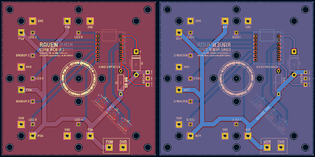
ok, 6:18 PM, and the first PCB is done!
gonna quickly commit, then update something on the LED panel, then do the motor PCB!
ok, gonna go to eat dinner now, just updated the LED panel fill so that it now has a solid conenction to the correct pads! (so, the ground pad is fully connected to the ground fill pour!) ok, its 6:26 PM now, see ya! (motor PCB next!)
ok whose linting the LICENSE file.
ok, its 8:30 PM now! time to start working on the motor subsystem PCB... (does this mean JLCPCB is gonna send a total of 15 pieces of copper to me (3 different PCBs)) also, forgot to say, the LED subsystem PCB actually now has 3 LEDs on it! this is to create 3 rings
that can be used for various purposes! speaking of which, i just realized i need to update the firmware folder to have two different firmwares, one for the led sybsystem and one for the motors!
anyways, 20A! yeah its 9:10 PM now and still connecting stuff! looking at it now, this 1N5822 looks rather small to handle 20A, lemme just double check that its rated for it... oh its not, guess i need to find another diode!
ok, here's one, the 30SQ045! it also has a datasheet! ok, updated the PCB and stuff (couldnt find a symbol or footprint online so i just put in some placeholder diodes and some big diode footprint that should work!) ok, time for measuring the motor size and stuff! hey, looks like they restocked their 150W motors? anyways, the datasheet on the site doesnt exactly provide very useful measurements, as far as distance between the motor bits go, so i guess im gonna do... idk, the diameter of the motor decreased by a bit? ill look around for more data first
yeah so i cant really find good info about the distance between the two prongs
of the motor, i guess ill just make a reasonably sized hole and just connect it with a wire in the future?
yeah so i actually forgot to add the hall effect sensor on the motor pcb... oops, gonna fix that right now
so these traces are so so so large, that trying to fit the mosfet on it is getting weird
ok, once again, i got jumpscared that we might not be able to power the STP55NF06L, theres a chance we might not be, since the max gate threshold voltage (for it to be fully open) isnt specified, and that graph is confusing as heck to read, so here's a IRLZ44N with the max gate threshold voltage being 2V, so it should be fully open! here's the datasheet!
ok, 11:32 PM update, been staring at this datasheet for quite a while, we might need some mini heatsink or something for the MOSFET, just really worried about it being too much for it
ok, so it should be good now? wirings super cursed, and tried to do the triangle thing as best as i could, guess someone should look over that?
ok, its 12:25 AM now, and here's the current (haha get it amps) (im going crazy) state of things:
yeah, so those are some very big traces. somethings bothering me, the ESP32-C3 isnt centered... also, we current are using the STP55NF06L footprint right now, while we're supposed to get the IRLZ44N. they have the same shape/footprint, but i should probably add some text on the silkscreen or something... actually i'll do that right now
ok, stuff updated! feels a little empty on the bottom, but we should maximize the support we get (10cm x 10cm boards are $2 on JLCPCB, so might as well maximize on how much PCB space we get) we should also find some way to add mounting holes, but that's for tomorrow! that also depends on the CAD, so we'll see! ok, good night!
Time Spent: 6.5 hrs
07-13-2025: Day 19: Finishing PCBs and Doing CAD Stuff
back to CAD i see...
ok, so today is the day of the yearly charging of the mouse! the battery lasts like a year on a charge for some reason, but yeah! also, while eating breakfast (at 1 PM since my sleep schedule isnt cursed), i remembered that we forgot to add the hall effect sensor on the motor subsystem PCB! so yeah, thats what we're doing first! (yeah i wrote i was gonna do it yesterday and just forgot)
since my mouse is charging, im gonna try to do this with my trackpad, what could possibly go wrong?
ok so turns out i just forgot to add the holes and stuff for the hall effect sensor
ok, should be good now? tried to keep it as far from the motor as i could (also, just realized that the vanity on both boards both say core pcb, fixing that right now!)
ok, 1:44 PM now and it should be good! broke out another pin on the XIAO (pin D9) which happens to be right next to the MOSFET controlling pin, so it would be a nice backup in the event that D10 explodes! also shifted the MOSFET and ground stuff closer to each other to minimize heat thingy, along with making the pads ridicilously big for heat stuff. ok, off for lunch now!
ok, its 2:16 PM, just came back from lunch! ok, so, since i cant CAD right now (mouse still charging, ill just leave it alone for now, even though it probably already is at 100% or something), im gonna start doing some firmware stuff!
wait im gonna brb in like 15 minutes, ok im back
ok so just updated the LED pcb to breakout the D8 pin as a backup for the hall effect sensor, all that needs to be done is to destroy the previous traces and link up a couple other ones in order to swap pins!
ok its 2:48 PM, brb, ok we're back at 3:20-ish! just updated the LED pcb to fix a little missing trace thats been bothering me, mouse is at 85%, gonna wait for 100% to start CAD! (i did just use it for half an hour to do something, but whatever)
yeah imma make this object oriented... its 3:45 PM, brb, ok its 4:00 PM now! ok, just wrote some logic for the LED subsystem stuff! gonna quickly commit, then do some motor firmware!
uh how do i write a pid controller from the ground up
ok, back from a little quick mosim break, i think the pid controller is good? im gonna quickly test it after taking a bit away (its 5:40 PM right now and im kinda tired) (even though i woke up at 12 PM)
back at 6 PM, somethings definitely wrong (theres no I value)
ok, so the issue was that i put very high constants and that my testing setup was messed up (i used = instead of +=), but it seems to work now! now how to implement trapezoid profiles...
ok, its 6:52 PM now, just gonna commit (kinda tired, starting CAD next!) (firmware isnt close to done, but we have a start)
ok, 10:15 PM and mouse seems stuck at 93%? anyways, CAD time! im starting to question whether this is a safe idea, but, i mean, ive been next to a speedy ankle biting robot before and some very fast spinning wheels, so this should fine (i might regret saying this). all i have to do is not activate it around expensive stuff! and maybe plastic wrap it or something (bad idea, heat might get stuck), anyways, just wear safety goggles or something
ok yeah so we kinda have a problem, this cad is gonna need lots and lots of changes... (trying to flip this thing upside down)
slowly getting there
ok 11:15 PM, im gonna take a quick mosim break
ok back at 11:30 PM, its super hard to think of where to set things up since we dont have actual measurements on the big fat part of the motor, but im planning on trying to make a 3D printable hub or something to connect to the round shaft
no way, frc 1778 chill out reference
yeah so its 12:30 AM, cleaned up the features, pretty tired now, here it is! (gonna finish tomorrow ig)
ok, thats it, good night! also, considering mounting the stuff for the motor PCB facing the bottom? might protect the stuff from the spinning disc more? (the status LEDs are whatever, pretty noticable?) probably actually a pretty smart move
ok, good night!
Time Spent: 7 hrs
07-14-2025: Day 20: CAD CAD CAD
cad cad cad
started at 5:45 PM, just updated the journal with the last 3 days! calculating the time for some of them were ridiciously hard, but yeah, we're back! anyways CAD time!
so we have to make this shaft collar REALLY strong, since the entire weight of everything else is relying on it, so i guess we design it to be a bit smaller than the actual design, so that it has to squeeze
it in order to have a tight fasten? then the next question is how to attach everything else... i guess making vertical holes is alright? the shaft collar has to be printed sideways, since that would maximize grip strength (dont want the layer lines splitting). i guess ill coat it with something?
ok, 6:15 right now, gonna eat dinner real quick
ok, 7:15 now and im back! its raining pretty hard here in NYC right now
some progress on the shaft collar...
research says that PLA sucks for shaft collars (funny behavior under heat) but it'll probably be fine right... (famous last words). ill probably shove random stuff inbetween it when i tighten the thing, while blowing air on it, so itll hopefully have more pressure? oh yeah, forgot to mention, this is a two piece shaft collar! (yeah, i just realized that the entire mass of this thing is relying on the operation of two screws)
ok, searching through my pla 3d printing waste bag, im gonna see the effects of squishing pla together! yeah, dont know what i was expecting, but squishing pla together does NOT make it fuse. yeah dont know what i was thinking. anyways, i got some extra ideas incase out shaft collars dont work! ok, so just added one, its a little extension bit about the shaft collar to make sure it doesn't slide down (it can slide up though), so we can add a fan blade pointing upwards to push the top half down wards if we need. that's a pretty sus idea if you havent noticed.
yeah so we're cutting clearance verrrrrrryyyyy close here, but it'll be alright
hold on a second i just realized this is mechanically impossible to assemble, one second... never mind, it actually is possible to assemble. ok, so you can close the shaft collar, but you cant open it. well, if you're opening it, it probably means its broken, so i guess its unnecessary? or just get longer screws
ok the solution is to buy 35mm M4 screws. since they come in sets of 20, i guess that would be 30 for the big spacers and stuff, and 6 for the collar shaft, and 4 for the future support stuff, then 40 small screws for all the LED panels, and that should be it? idk, thats for BOM later
you know, i would love to CNC some of these parts, except i dont exactly have a cnc.
wait a second, those two things are probably gonna collide
ok, now we have a REALLY big shaft collar, but it shouldn't collide? might collide with the lower bit connection now, but we'll see
ok, all we have to do now is make the connection from lower pcb to mount the motor, then connect the shaft collar to the upper bit, then assemble the whole thing (in the assembly of course, not real life just yet)
ok, just moved some stuff on the PCB so that we have more space for these supports! just got an idea, instead of having vertical supports from each one, we can have two quarter shields
that provide more support than one skinny cursed spacer! also probably looks better. (wait let me DRC real quick)
ok, here it is!!!
yah looks ok, anyways, top mounting and bottom mounting now. since things are a little weird, i kinda need long rods in my BOM, as in, we dont exactly have space for a clean mounting solution (as in, more holes), so its probably better to shove a long rod in replacement of a screw there. that sounds like a horrible idea, lets not do that. oh wait, this is just silly, we just do the same thing we did on the top on the bottom, then make some triangle cone shape thing for support
ok, time to do good parametric cadding by using variables, time to update every feature! (we have 61)
actually, 0.42mm is probably good for a lot of stuff, so gonna just update the reallly necessary ones
wait i just realized, we're really covering up the motor's air cooling
intake
ok, bottom mount updated! might need to get 40mm screws now, but looks good! now we just need to do the little bottom support triangles. also, we forgot the place to put the battery and other electronics (oops). it's meant to be like a little thing that sticks out, but we'll see in COG analysis! (and real life, since the PLA parts aren't going to be 100% infill)
you know, sometimes its nice to show all sketches and hide all parts...
ok, its 10:16 PM now, im gonna brb (probably near 11:30 or something idk) (imma commit now)
ok, turns out i came back at 11:28 PM, so very close! ok, back to CADing... im not sure how to do these stands since we only have one point of attachement right now, probably something you can just screw mount it to on the other side? wait i just had a REALLY good idea! we just mount it to the same mounting holes as the top led subsystem plate! it's got all the silkscreens already, we just have a nice copper thing we can mount this all onto! and its already got pre-drilled holes and stuff! ok, we need 8 mounting things now...
just retaught myself how to use lofts again! (barely use them...) ok yeah lofts might not exactly be useful right now? actually they are, i change my mind once again. yah that does NOT look stable.
ok, its been a while now (12:14 AM), and i think we got something!
yeah, it looks kinda weird, but should work? also why does java say its ready. oops, forgot to clip the corners (it would awkwardly stick out on the pcb)
ah, there it is! ok, its 12:20 AM, gonna try to speedrun this top part
12:30 AM, and here it is!
it's not one piece (its actually three), and consists of the little spacer from the washer to the alignment disc
, which just gives the led subsystem PCB a place to actually connect to! i might consider moving the LED subsystem mounting holes a bit wider actually... maybe later? all we have to do is make sure its all balanced when we actually assemble this! ok, lastly, we'll just have an extra arm where we'll ziptie all the future electronics or something, so yeah, all that's left is making the assembly!
so im a little confused of how 0.5cm of height magically appeared from nowhere. however, on a more positive note, i just found out how to save some height! now that i look at it more, we somehow lost 0.3cm?
ok you know what, its 1 AM, ill work on this tomorrow! guess the finish date will be pushed to 7/16/2025? idk, CAD and firmware and wrapping things up sounds ok? alright, good night! (its 1 AM aaa)
Time Spent: 5 hrs
07-16-2025: Day 21: More CAD!
more cad. and some screws!
what happened to 7/15/2025? well, i kinda got distracted with YOLO (like, computer vision) and made a model that detected white toilet paper roll cardboard thingies. apparently im also one of them (there were no picture of people in the dataset so thats probably why). anyways, currently, forcing another laptop to train it off of a bunch of FRC game pieces, and its been running for like... 9 hours? epoch 22/50-ish (yeah i dont exactly have a beefy GPU laying around)
anyways, im back! its 5:41 PM, lets see how long my laptop lasts (its at 31%). ok, its actually now 6:00 PM and that other laptop is still going! ok, cad time!
6:17 PM update, here's how it looks! still need to add all the screws (theres gonna be a lot of them), and the electronics area, but so far so good! i also removed the extra spacer, bringing out lower clearance to 1.2cm!
its 7:21 PM and i think thats a couple screws
so uh i cant even count how many there are, so im just gonna measure the total volume and divide it by the volume of one of them! so there are $\frac{24.943163}{0.639568}$ (39-ish) M4 40mm screws and $\frac{31.44751}{0.388241}$ (81-ish) M4 20mm screws. whats funny is that they come in batchs of 20 (if i remember properly), so that kinda means that i should get rid of one screw somewhere... ok, removed the center one (this cant possibly go wrong right) so we now have $\frac{31.059269}{0.388241}$ (80-ish) M4 20mm screws! (wait so we have like 120-ish screws... wow)
i dont wanna add these bolts D:
ok its 7:40 PM, ill add those bolts later!
just kidding i updated the pcb with the mounting holes!
ok its dinner time (its 8:05 PM now), see ya!
its 1:48 AM and im kinda getting tired of running these YOLO models... anyways, its computing overnight and im kinda tired, so good night! (will try to finish tomorrow lol)
Time Spent: 2.5 hrs
07-17-2025: Day 22: That's Nuts!
thats nuts!
oops its 9:17 PM, adding nuts now (yep getting straight to work) (wait im gonna import the PCBs into onshape first)
onshape is very sad and slow when importing these pcbs...
huh onshapes geting a little faster?
ok, holes cadded, that took surprisingly long to import, time to add the nuts!
no way, square nuts are a thing?
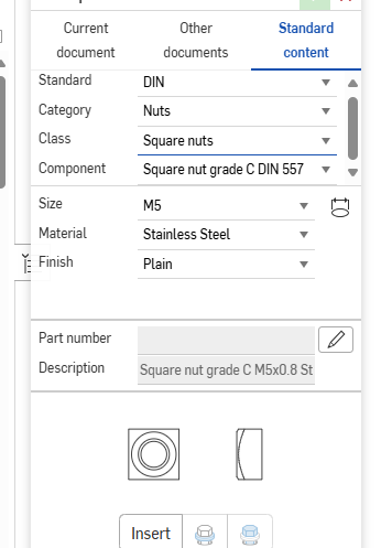
so turns out i should make it 0.82mm spacing or something (greater than 0.808) instead of 0.7mm spacing. whoops. also, wow, that means that these screws and nuts are SMALL! anyways, 10:24 PM now, most nuts added, just gotta update the spacing of lots of stuff... (benefits of parametric cad!)
wait im gonna go watch a movie (its 10:45 PM right now)
its now 12:12 AM. before i went to watch a movie, i updated a couple of the spacings of stuff, so now its time to update the cad. again! ok, exporting from kicad now... ok, importing into onshape now... ok, onshape doing its thing now...
why is it -0.790000 cm instead of 0.8. ok, silly mistake fixed, importing again...
ok, updated the collar shaft! ok, screws updated, assembly repaired, doing some final checks now!
ok, CAD looks good! just a little note, seems like the holes on the PCB can be a bit further away from each other! might actually connect the inner vertical screws on the lower motor support plate to the ones on the motor top mount... (i will need to steal 4 screws from somewhere)
oh i actually just found where! the 4 screws we have for the outer spacers for one of the arms are kinda unnecessarily long (they literally collide with each other) so i guess we replace those with some shorter screws
ok its 1am now and im going up to school tomorrow, so i guess im finishing this tomorrow? (please)
here's the current state of things! (currently doing the changes with the mounting, so thats why theres a couple missing screws and nuts on the lower motor support plate)
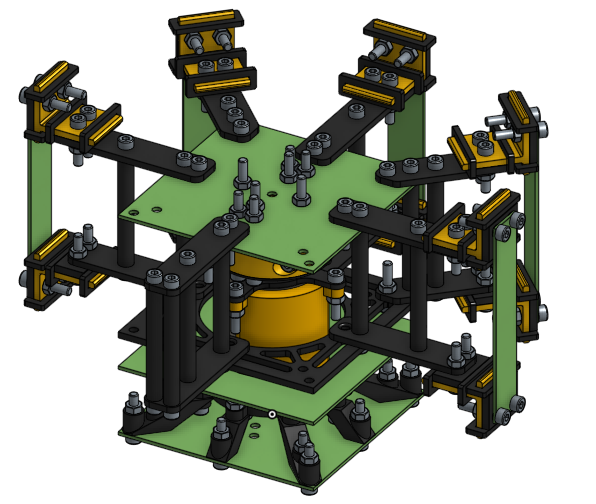
ok, good night!
Time Spent: 2.25 hrs
07-18-2025: Day 23: CAD and Safety
ouch
hey! its 6 PM now, kinda tired (i got a giant cut from a piece of polycarb today), but we're so so so close to finishing CAD! found 20 zipties from a random box today, so that'll probably be enough to mount the electronics
ok, just updated the PCB, why does the mounting area remind me of the Limelight 2 design
ok, its 6:30 PM, updated the CAD and stuff, just need to add a couple bolts and it should be good! after this, we go to firmware! (but dinner first)
ok, its 8:45 PM and im back (had some meeting)! turns out i did a silly, and i just realized i did more silly. basically, we removed the middle mounting holes to the straight right of the center of the led subsystem, so theres nothing there (meaning, we have to move some stuff to the side). additionally, 40mm screws are kinda way too long for these spacers (shouldve noticed this yesterday, but they dig into each other on every long spacer. oops.)
solutions? fix the arm mounting (also figure out where we put this hall effect sensor) and replace all 40mm screws with 30mm. or something. (we still need 10 40mm screws though, 4 for the motor mount, 4 for the connection to the top, and 2 for the shaft collar)
it might be smarter for me to just add the holes back onto the led subsystem, since we're gonna have to wire this hall effect sensor anyways (theres nothing non-moving for the magnet to be on, if the hall effect sensor is soldered directly onto the board)
also, just realized the center text still says CORE PCB
here's a before and after! (left is before, right is after)
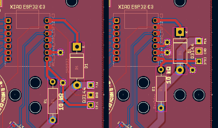
updating that silkscreen now... so uh im trying to remember how i did this. i remember my steps, but i dont remember the settings... ok, just finished updating it! text is a bit smaller, but still is there! (all text on the PCB will probably be kinda super small)
you know, i think this is a bit obvious, but that idea from yesterday to connect the two bits? turns out thats connecting the inner motor part (doesnt move) to the outside spinning part (that does move). yeah, i really shouldve seen this one
ok, working on fixing it, currently 10:30 PM, ill be back in a bit!
back at 11:46 PM! currently going through the CAD to see how many screws each (20mm just got updated to 16mm) we need, trying to aim for multiples (or just below) of 20, since we dont want to buy a bunch of extra screws we dont end up using
also, quick side note, i do NOT remember the keycaps on the macropad being this smooth (maybe i finish hackboard now? i did finish it back in march, maybe ill redesign it)
list because paragraph form is unreadable: - M4 40mm screws - $\frac{6.395683}{0.639568}$ - 10 screws - M4 30mm screws - $\frac{12.33371}{0.513905}$ - 24 screws - M4 16mm screws - $\frac{28.389932}{0.337975}$ - 84 screws
yeah so while calulating the screw counts, M4 16mm screws had a suspicious decimal. turns out a couple M4 30mm screws snuck into that folder. anyways, those are very sad not multiples of 20. ideally, it seems that the fastest solution is turning 4x 16mm screws into 40mm, and 4x 30mm screws into 40mm.
yeah i dont know which screws to change out. but on a side note, just fixed a couple spacer issues!
im gonna write up a quick essay on what everything is so far, so we get a general idea of what this is! (its probably gonna sound so robotic)
i just realized the journal has the wrong project on it. whoops.
Introducing Raven, an open source spinning LED light display! The system can be seperated into three parts: the motor subsystem, the LED control subsystem, and the LED panels. But first, what exactly is the idea behind Raven? Inspired by the light effects done at BattleCry 2025 at WPI (2025BC), along with really liking LEDs for some reason, I wanted to create a LED display that lights up an entire room. But a stationary system wouldn't create the desired effect, the effect to slice up the room into different colors. For example, imagine the left side of the room being red and the right being blue.

This is accomplished by having 5 LED panels, each with 10 LEDs each, vertically stacked, pointing outwards. These 5 panels form a 180 degree circle, each panel spaced 45 degrees off the next. Arms connecting to the top and bottom of the LED panels attach to a center. Spacers keep these top and bottom arms in position. In the center, the top arms connect to the LED control PCB, which contains a XIAO ESP32-C3. This board is also equipped with a Hall Effect Sensor, used to be a simple way to measure RPM without an expensive encoder. This entire section spins on a shaft collar connected to a 775 motor. Additionally, a 18650 Li-ion battery is on this section, powering the whole thing without need for a power wire.

In order to save on costs, a slip ring was strongly avoided during design. Instead, the motor subsystem powers the motor with 4 Li-ion batteries, supplying a total of 14.8-16.8V @20A to the motor. 4 Li-ion batteries was choosen as a solution to the problem with finding suitable boost converters, which were either incapable of handling 20A, or are just really expensive. In fact, it is actually cheaper to use 4 Li-ion batteries than a single one of these boost converters. This solution also gave the benefit of having additional battery time, which was a nice side bonus. The motor subsystem is stationary, with the base being a copy of the LED control subsystem's PCB. This empty PCB is used as the FR-4 material of the PCB is likely stronger than PLA parts, while also being a smart way to reuse the multiple PCBs sent by JLCPCB. This is also the reason why there are 5 LED panels, as to minimize waste. The motor subsystem is also powered with a XIAO ESP32-C3, and has its own Hall Effect Sensor to measure the RPM of the LED subsystem.

The control system starts at the stationary motor subsystem microcontroller, which sends a constant ping to the LED subsystem's microcontroller. The LED subsystem reads this ping through the ESP32's bluetooth capabilities, and also sends a ping back. Both systems need to listen to each other in order to think they are operating properly. In the event that a ping isn't heard in a long time, the LED subsystem will stop operating and the motor subsystem will attempt to bring the motor to a stop. While operating properly, the LED subsystem uses a mix of data from the motor subsystem's Hall Effect Sensor and the LED subsystem's Hall Effect Sensor to calculate its speed and position, utilizing a model of the motor's speed. The motor subsystem will use PID control with a MOSFET to ensure that the LED subsystem reaches the proper spin.

This entire system is packaged inside a cylinderical shape with diameter of roughly 24 cm and a height of roughly 15 cm. The LED subsystem, weighing less than 2 pounds, plans to spin at anywhere from 1k-2k RPM, in order to achieve a speed where the LEDs essentially blend into a blur. The LED subsytem is loaded with almost 120 screws, in order to ensure that the LED subsystem stays in place. Additionally, all batteries are protected inside an over-discharge protection board and charged with a TP4056 module with protection (the TP4056 does NOT provide power to the system, it is only used for charging.).

And that's Raven, an open source spinning light display!
that took 20 minutes... i think i touched on all the points? ok, gonna write a quick checklist of things we need to test before actual trusting it!
Post-Build Test Checklist: - Mechanical - All screws tightened, loctite applied (or other things) - No bends anywhere (especially the arms) - Shaft can spin freely by hand without power - All wires secured - Battery securely mounted - Initial test (100-200 RPM) - Powered on in a safe enclosure - System can spin without wobble/vibration - No expensive noises - Hall Effect Senssors read the correct RPM - Failsafes work properly (with simulated ping loss) - Tuned motor PID controller - Electrical and Thermal - Battery voltage before/after test recorded - Motor MOSFET not overheating (using tools, not your finger) - All LEDs operate properly (no flicker/signal loss) Bluetooth connection stable under spin - Safety System Checks - Failsafe shuts motor and LED subsystems off - Manual kill switch tested - System shutdown behavior is controlled (no violent stopping, etc.) - Additional tests - INSIDE A SAFETY CAGE - Start at 250 RPM - Increment until 1500-2000 RPM - For each speed: - No vibration increase - No parts shifting/shaking - RPM proper readings - LED visuals appear as expected - No excessive heat - Post-Test inspections - Check and retighten all screws - Check all mounting points for cracks - Check any logs - Check all wires, boards, and solder joints - Endurance test - Aim for 3 days of total running with no issues - Several cycles per day, at different speeds - Check temperatures and operation for all cycles - Save logs - Look at logs for any strange stuff!
ok, its 1 AM now, good night! so we just have to assume a BOM, change some screws, and yeah! also, quick note, might want to make the spacers have smaller holes near the ends in order to force the screws to grab onto the spacer (so that it, you know, actually does something) but yeah, that and some firmware! (probably better to have it, but whatever, we'll make a thorough editor sometime in the future!)
ok, good night! (uh oh gotta update journal for a lot of days...)
Time Spent: 3.5 hrs
07-19-2025: Day 24: BOM (again)
and the zoo
so today i went to the zoo. for like the entire day. was pretty fun, but that was a LOT of walking. why is hackatime say that i spent 2 minutes ai coding. what does that mean (i removed all the copilot extensions and disabled the features a while ago?). anyways, back to CAD! currently have mc open in the background just clearing out a large area automatically (if only we could achieve such good pathfinding in frc...), so yeah, time to fix some CAD and write firmware! (9:00 PM right now!)
thinking back to yesterday, i think that its probably better if we just make the entire spacer have a smaller inner diameter, instead of a just a bit on the top and bottom, since we'd want the entire length of the screw inside material (it will be a pain to thread it though)
the entire assembly, in fact, did not explode! thats shocking... mightve said that too early, all the M4 30mm screw replicates contain errors
9:30 PM now, gonna quickly do something and be back, back at 9:45 PM!
so i cant really solve this screw problem. yeah. so i guess ill figure that out in the future? ok, BOM time! ill assemble this into a chart, but im just gonna toss over some links and stuff for now
Structure: $20.83
- M4 Screws: $12.23
- Note: only allows M4 sizes in groups of 20
- ALSO REQUIRES SOLVING THE SCREW ISSUE
- $2.62 for x20 40mm
- $2.29 for x20 30mm
- $7.32 for x80 16mm
- M4 Nuts: $8.60
- Note: only allows M4 in 25 pieces
- $8.60 for x125 M4
- 3D Printer Parts
- $0 (will use my own filament!) (im guessing i might run out of yellow/black filament, might get more)
- M4 Screws: $12.23
Electronics:
- PCBs (using JLCPCB): $19
- Note: I think 10cm x 10cm boards are $2, but I'm just setting them as the undiscounted price just in case
- $4 for motor subsystem
- $4 for led subsystem
- $4 for all LED panels
- $7 for shipping (might change)
- Electronic bits:
- $10 for x2 XIAO ESP32-C3
- $9 for shipping? looking for better solutions...
- $1.12 for x5 A3144 (hall effect sensor) (min of 5)
- $1.42 for x5 IRLZ44N (MOSFET) (min of 5)
- $1.06 for x2 30SQ045 (motor diodes)
- $4.28 for x65 WS2812B (multiples of 5)
- $0 for solder (will use whats left from the hackpad thing) (it would be nice if you could send some :D)
- x2 1N4148
- x2 10 kΩ resistor
- x1 100 Ω resistor
- x2 DIODE FOR XIAO
- $10 for x2 XIAO ESP32-C3
- Motor: $16.77 (assuming no welcome deal)
- $16.77 for x1 775 Motor (288W, 12k RPM)
- Note: I'll try to use the welcome deal to get this down to $0.99, but this isn't certain
- $16.77 for x1 775 Motor (288W, 12k RPM)
- Batteries: $25.45 - $41.20 ($41.20 being the absolute MAX)
- $30 for x5 Samsung 25R 18650 2500mAh 20A Battery
- NOTE: THERES CURRENTLY A SALE WHERE IT ONLY COSTS $14.25 IN TOTAL AS OF 7/19/2025
- $9.13 shipping
- $2.07 taxes
- $30 for x5 Samsung 25R 18650 2500mAh 20A Battery
- Overdischarge Protection
- $1.16 for x1 1S 16A Overdischarge Protection
- 4S 20A not found yet
- PCBs (using JLCPCB): $19
why is digikey loading so slowly
ok, still writing the BOM (yes, these messages will not be in order for you, but whatever), and its 11:20 PM. im feeling kinda tired so ill be back in like 10 minutes or so.
comes back at 1 AM
ok time to continue
im tired, list almost complete, just some electronic bits for the board and finding the 4S 20A overdischarge protection and assembling the list! good night!
Time Spent: 1.75 hrs
07-20-2025: Day 25: Code and MOSFET Nightmares
there must be one out there...
ok, got some motivation today, its 1 PM, and ive decided that today shall be the last day to work on this! i really need to get started on other stuff, and this has simply taken almost a month (which is kinda crazy long, given that we thought we could finish this in like 1-2 weeks). anyways, after this, ill be working on IVO v3, until i get some update on what will come of this project! (then parts should ship by august 4th or someting, then building by august 8th).
ok, first things first, i decided last night to look at yet another MOSFET, since im absolutely terrified if the MSOFET we choose isnt able to fully turn on at 3.3V. this time, i already memorized its name, the IRLB8721PBF. its lead free too, which i guess is a neat bonus. just check the datasheet and im not sure if this works. basically, the issue is that the graphs are confusing as heck, and that 3.3V GPIO pins seem to just turn on
the MOSFET, but not all the way. really considering just having another switch just control the MOSFET at this point, connected to the 5V line and having that output feed into the logic pin of the motor MOSFET.
ive been looking at a lot of MOSFETs. oh wow its already lunch time (i just ate breakfast), i have an idea for the screw solution, but i requires me removing two LEDs on the motor subsystem (which im alright doing)
ok, 1:30 PM now, gonna look at some MOSFETs while eating lunch, back at 2:15 PM, ive looked at way too many datsheets and videos. its been a bit and just watched this video for how MOSFETs work, and i think ive confused myself (how do you wire it???)
ok so i need to find a heat sink or something (im just gonna find some big piece of metal somewhere)
yeah so our wiring for the mosfet is kinda sus
its 3PM and i feel like falling asleep so im gonna take a break
its 5:15 PM and i think im gonna pause the MOSFET thing until later. worst comes to worst, i grab a BJT and use that on the 5V to output 5V into the MOSFET and that should do the trick. for now, im gonna work on mounting, then work on the programming side!
yes i just spent the last 15 minutes redrawing a qr code image into a 29x29 image in microsoft paint.
just realized i was doing all my work in the wrong assembly. anyways, had some fun with vanity, added the hc inside sticker and a qr code to the repository on the PCB! 6:45 PM now, heading off to dinner.
its 12:00 AM and im back (no i did not spend 5.25 hours eating, i was forced to touch grass and do other stuff). so we didnt exactly finish today, but let's keep going!
CAD updated, here's a quick picture (notice the changes at the base)
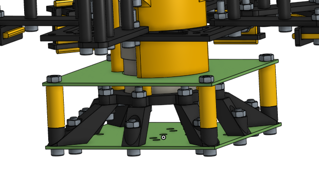
ok, quick commit, then some coding!
yeah so im pretty sure we aren't hitting 62499999987.267075 FPS.
ok, updated the motor subsystem firmware, its 1:15 AM, gonna head to bed now. got a couple things done (PWM, clock, docs), i guess finishing everything today was a bit ambitious, hopefully ill wake up earlier tomorrow? (wow these docs are way too formal but whatever) ok good night!
Time Spent: 4 hrs
07-21-2025: Day 26: Code!
programming stuff!
today does not exist (as in, shouldnt have). anyways, its 11:23 AM (my sleep schedule is horrible), time to continue writing code! ok its 11:29 AM and now its lunch time.
ok its 6:23 PM, came home a bit ago, but back to programming!
ok, lots of work going on in the led firmware, currently thinking of the equation to measure the rotation position, at least mathematically wise. ok, this markdown file shall be my rubber duck.
so we need to find the rotation position in a given timestamp (now). so, using the hall effect sensor, we can estimate the RPM, which is good. say, we are currently at 1k RPM, we can tell how long each rotation takes by taking the reciprocal (so, 1/1k = 0.001 seconds). however, we need to find our position, so we can take our timestamp and modulus it by the length of time per rotation, so we can find out how much time into
the rotation we are. for instance, (0.0015 % 0.001 = 0.0005), meaning we are 0.0005 seconds into the rotation. then, we have to divide by the length of time per rotation to get how much of the rotation is complete (0.0005/0.001 = 0.5). therefore, we are 50% into the rotation!
so therefore, our calculation is (TIME % (1/RPM))/(1/RPM). we might as well store 1/RPM into a variable to make it more compact, say (TIME % n)/n. looking back, this logic is a little flawed when we consider that rapidly changing hall effect sensor number will confuse the heck out of the system (since, modulus doesn't fit exactly
into everything), so we might need to implement something with a counter and time difference if this appears broken. we also need to take care of when RPM = 0, i guess just add 1e-6 or something there
now thinking about how to implement the color data stuff (for now)...
ok 7:17 PM now, gonna commit and eat dinner!
got distracted by mosim and its now 9:14 PM (oops). anyways, more led work time! for now, i guess we'll just have a simple scripting system that just has a rainbow swirling around (more advanced stuff if we can find out how to do this).
so ngl, every time i want a smooth LED rainbow, i always go back to the LED subsystem from our 2024 robot and copy that function (since, it worked really well, imo)
well, that seems to be working! gonna quickly make a visual testing setup (no we are not bringing in IVO... yet)
ok, got the matplotlib thing working, seems good so far!

i think the LED subsystem code is good for now? i mean, sure, needs testing irl, but i think the logic works ok for now? added some docs too! ok, time to finish the motor subsystem firmware...
still need to implement the bluetooth stuff, but its probably better to figure that out before soldering anything
ok its 10:05 PM, im gonna go check mc quickly
my internet just blew up again. anyways, im gonna watch a movie
ok, back at 12:06 AM! i think the motor subsystem is pretty much good (only thing for now could be feedforward?), so im gonna commit it! we're gonna need to figure out the bluetooth stuff before writing more control code, but im gonna have to have the microcontroller in hand to test it with! ok, quick commit, then back to cad, hope that i dream up some solution to the MOSFET issue tonight (it would be really funny if i magically had a lucid dream tonight (ive been trying here and there for like 2 years at this point, maybe i actually try in august? oh wow a third of summer is over already))
ok, we have x80 ($\frac{27.038031}{0.337975}$) 16mm screws! first part of the problem solved... hmm x24 30mm screws, gotta change 4... you know, i cant actually do this without messing up some stuff, since those 24 are used for the 2 layer x 2 screws x 6 arms? wait i just got a good idea, we can just add some spacer to the top or bottom and call it an expansion
thingy, since we'll have to mount electronics on the extra arm anyway.
yay! the screw issue is solved! we have x80 ($\frac{27.038031}{0.337975}$) 16mm screws, x20 ($\frac{10.278091}{0.513905}$) 30mm screws, and x20 ($\frac{12.791366}{0.639568}$) 40mm screws! and some 86 nuts! in the assembly, there's 100 total instances and 57 mate features!
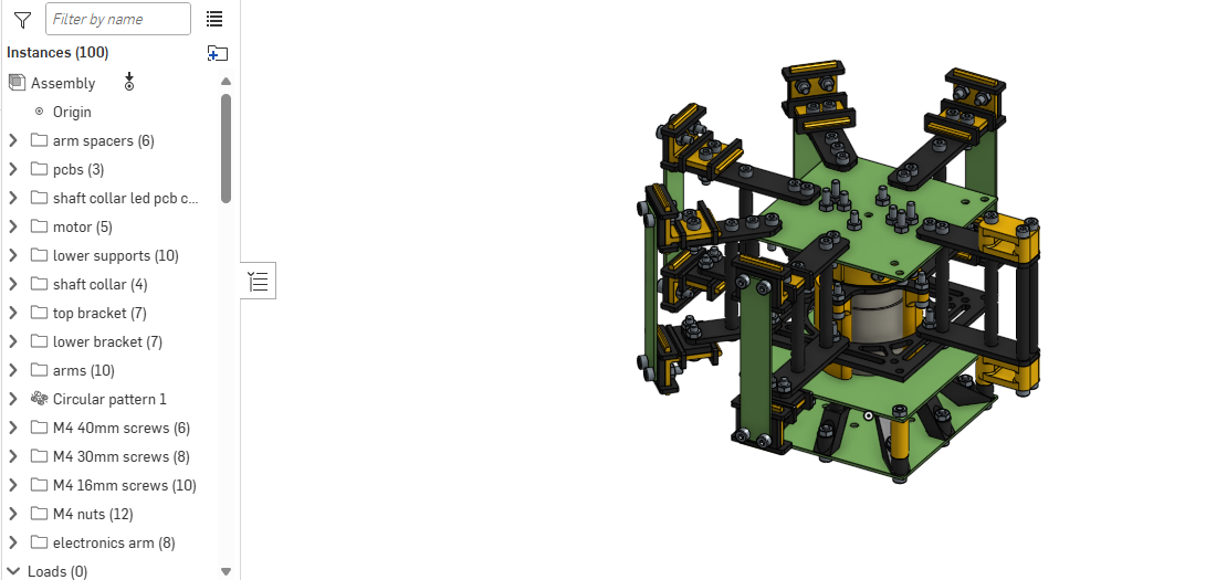
ok, its 1 am now, CAD needs a little bit of clean up, but its presentable now! good night, hopefully can assemble a complete BOM and start preparing this repository for presenting tomorrow! (and whatevers left for submitting). ok, good night!
ok quick update, i was about to commit, then i remembered we still need to sort out the MOSFET thing and check for electronics to CAD collisions. but anyways, good night!
Time Spent: 3 hr
07-22-2025: Day 27: The One MOSFET!
found the one!
idk why are started reading the rust book. but looks pretty interesting, its like python, java, and javascript made a new language together, but this language is kinda on something (read the first three chapters, probably gonna re-read it, guess that another thing for this summer). anyways, found an overdischarge protection thing today too! just gotta move the link over (havent looked over the specs just yet). also, last night, i also started reading some art book. (huh maybe i should start reading some of my summer reading book)
also, ill REALLY try, but hopefully if we finish fast enough, i have time to draw some banner art (i have silly idea). anyways, 5:07 PM, here in NYC, time to get started!
here it is! (choose 4S 20A Standard). unfortunately, its kinda super sketchy (not too too many buyers, also specs seem a little suboptimal)
ok its 5:48 PM now and im gonna be right back. so its 5:54 PM, and im back, so i just licked a couple crumbs of a snack off my table, then remembered this is the same table i left little microplastics on, soldered on, accidentally dripped super glue on, and opened some cursed keyboard on. yeah, might not have been my best move. anyways, back to aliexpress
hmm heres another one (why do the links look so similar) (choose 4S 20A Standard)! i do not understand what this chart is saying. seems good though, not sure how 20A fits on those traces, but reviews and reviews look real!
ok, gonna check that CAD is good, gotta figure out the MOSFET thing, then BOM!
just updated some mates being a tiny bit off, should be centered now!
ok, CAD looks good! also, last night, i had an idea, what if we use like those little adapter or whatever they're called, but the things that you screw that squish a wire and creates a connection? i think its called a set screw terminal? soldering is probably ok, not gonna lie
ok, electronics updated, its 7:08 PM, im going off to dinner, gonna think about the MOSFET stuff!
back at 9:46 PM, time to look at MOSFETs again! gonna double check on the IRLZ8721PBF datasheet again, yep probably not. turns out digikey has a nice thing that says Drive Voltage (Max Rds On, Min Rds On)
.
i am now in a reddit rabbit hole
ive found the digikey
thank you digikey! (here's the search) even though im gonna look if lcsc has it! thank you digikey!
what is texas instruments doing, just searched up CSD25310Q2T and theres no way that 0.2cm x 0.2cm thing handles 20A. anyways, that would be quite the pain to solder on. ok, gotta keep search, filters might be too small
ok, played around with the filters a bit more, here's the new search!
im just gonna make a list at this point (so many of these arent available on LCSC)
i think i mightve just found the one! the AOS AOD424, with specs of: - 20V N-Channel MOSFET - VDS 20V, ID (at VGS=4.5V) 45A - RDS(ON) (at VGS=4.5V) < 4.4mΩ - RDS(ON) (at VGS=2.5V) < 5.7mΩ - Drive Voltage (Max Rds On, Min Rds On) 2.5V, 4.5V - Rds On (Max) @ Id Vgs 4.4mOhm @ 20A 4.5V
here's the page! ok, so it seems to able to be driven at 3.3V? if VGS=4.5V allows 45A nicely, then 3.3V should be able to fit 20A?
ok, being told to go to sleep already (its 12 AM), guess ill try to wake up earlier and finish the electronic tomorrow? glad the MOSFET situation is ok now? (we need a heatsink though)
ok, good night!
Time Spent: 4.25 hrs
07-23-2025: Day 28: Adding That MOSFET!
more mosfet stuff!
yeah so i woke up at 8 AM, then fell asleep and woke up like three times, but now its 11:22 AM. i have like, maybe 10 minutes before i gotta eat lunch and head out, so lets make this super quick!
hunting down the AOD424 footprint thingy (snapeda time). uh theres no symbol but there is a footprint. hmm, imma just, send a request
so it seems like the STP55NF06L has a similar symbol (except... is that a squiggly?) also, we have to pull down this line too (i think? saw something like that somewhere, gotta look into that), so i guess we're making symbols today?
ok, 11:36 AM now, gonna look into how to make kicad symbols (gotta go eat lunch and go outside now) (and read more of that rust book)
ok, back at 6:12 PM, just realized we have a lot of stuff to update in the journal... anyways, think im ready to try making this symbol! just gonna check if snapeda did it yet... nope, they just released some bot or something. anyways, to kicad!
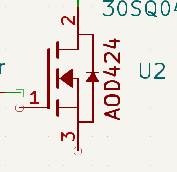
woo! added made my first symbol! i think it looks pretty similar to the datasheet! couldnt figure out how to make another symbol field, but whatever, yay! now gotta figure out how to wire this... ok, so to my understanding, we shove power down the gain of the N mosfet gain, and that creates a connection between source and drain, so more power, more speed, but the capcitor stays loaded, so you have to connect the capciator to gnd, or else gate stays too open?
ok, i think i got the wiring down, i just need to recalculate the heat thing to make sure we dont get a fire
its 6:48 PM, currently trying to find what footprint i used for the 10kΩ resistor last time, and yeah, updating the PCB! (off to dinner now!)
ok, back at 8:30 PM! so for later, im thinking about the reveal video for this (yeah theres gonna be one!). i was thinking of the background music, and i have two choices, gotta decide on it! anyways, back to kicad! im now confused on how to wire it and im watching the video again
just watched that video and another one, seems like the wiring is ok! moved around a couple resistor positions, then renamed the A3144E stuff to just HALL, PCB time!
ok, 10:26 PM, watched lots of MOSFET videos, looked at chart 1 of the datasheet a couple times, i think it looks ok? (side note: it seems that asking the omniscient ai does not work very well for this, since it cant exactly convey the information very well. its also lots of times wrong.)
also, broke symmetry on the motor power pads in order to all for more space for the MOSFET stuff, hopefully thats a good enough space? ok, added back symettry, should still function though (dont worry, mosfet still has the same amount of space!) DRC seems ok, time to do BOM! gonna actually do this in another file...
huh internet blew up again, why is it always at 10:40 PM ish, im gonna watch a movie now (its 10:48 PM now)
ok, back at 12:12 AM, seems like the internet blew up from my side (internet adapter or whatever sometimes does this i think?)

wow thats crazy, i dont have an ethernet port, and the wifi works perfectly fine! idk what the issue is but i guess this model of computers just breaks the wifi stuff side of things whenever put into sleep? ok, restarted, and we're back! BOM time!
ok, just need to find some links tomorrow, and we should be almost there! phew, cant believe its been 28 updates already... also, note to the first update log, doing three projects at once isn't a good idea since youll only end up doing one of them at a time (and its this one!)! ok, its 1 AM, i think i put a couple too many notices about the BOM being the worst possible case that could happen to you (like the theoretical max price, as in, no deals or promotions), but yeah, hopefully nothing bad happens that raises the prices (no, do not say subtle foreshadowing.)
ok, good night! (wow, i have 5 update logs for the journal...) good night!
Time Spent: 3.75 hrs
07-24-2025: Day 29: More BOM Stuff!
and parts finding!
ok, 11:49 AM right now! last night i remembered something about flyback diodes, so imma look into that in a bit. also, i forgot to add magnets to the BOM... wait is copper magnetic? oh ok it isnt, gotta double check that out crews and nuts arent magnetic either... so the screws are magentic (they arent magnets, they would just be attracted to them if brought near though) and the nuts shouldnt be. thats alright, just gotta position these things well (depends on when we actually get these parts!)
well, i went to lunch after that at 12:00 PM...
back at the 5:55 PM timing circuit (get it the 555 timing circuit, anyways), gonna watch a couple videoes.. big thanks to this video for speedy info, and this video for more deeper stuff!
wait, just remembered that i wanted to calculate the tangental velocity or whatever its called in the even that an LED or something detaches and flies off... so for a 2k RPM at 12.5cm radius, we have a tangential velocity of 26-ish m/s, according to this calculator, or 58.6-ish mph. 1000 rpm does 13-ish m/s, or 29-ish mph. ok, so theoretically not too bad if it hits (well, an LED, if the entire 2-ish pound disc slammed into your face, you probably wont feel so good). still gonna first test this from a different room lol
anyways, back to looking at flyback diodes! hate to sound like one of those youtube bot comments, but the second video really pulled the whole idea together (i recommend if you're also doing a motor mosfet setup thingy). anyways, time to implement it! (java reference?) (java reference reference?)
wait i just did a big silly, i did not need to leave that much clearance since the top of the board is the bottom on the actual thing.
this might be one of the most cursed things ive done in a while but ok, we're gonna have to mark which ways the diodes are supposed to go. its 6:48 PM, off to dinner!
8:00 PM and back, just had an idea for a bit more vanity on the PCB! actual, on second thought, probably not too good of an idea, lots of it gets clipped by the pads! gotta update the position of a couple stuff since screws are coming way too close for comfort for some of them
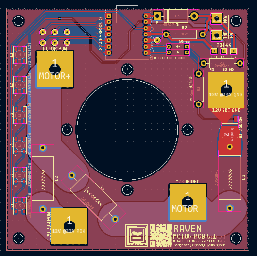
there it is! moved the MOSFET a bit more to the right, (also probably a good idea anyways, since it makes things a bit closer), broke the symettry of the motor pads, but its fine (close enough
). wait, if we move the vanity (i really dont wanna do this), we could theoretically get better traces (i really dont want a fire/overheating issues you see) on the MOTOR-... yeah i guess its a good idea for performance.
currently 8:47 PM, adding a bit of silkscreen art for fun
moved the motor trace to be more straight (should hopefully not create excess heat), shifted the bottom text to the middle (still looks good!), and added some art
ok back to BOM time! gonna do a quick commit first...
mfw i remember i have 5 or 6 journal updates to do
$9 shipping is crazy
i can not find these resistors. oh, turns out only 2 are in stock for the ones im looking for (i guess its way too specific?) the Through Hole,D9xL36.5mm package is crazy. ok, 10W is NOT flowing through this (as in, our load will not need that much), so we do NOT need these mega sized resistors
ok, found some better resistors (cheaper too!), this time not gigantic. its rated for 1W, which should be more than enough headroom. they might be a bit small for the PCB, but it should be fine? now, time to find some diodes for the xiao...
ok, sent them a help quesiton about it (imo the docs are a bit confusing on this), trying to understand what it means (cant be too careful), got hit with this:

spoiler: i cant really read chinese. i do know what the last character is (i know like a few characters from years ago), but all i know is that its likely a question. which doesnt help because theres already question marks. (luckily, these days we can just translate this, no, i did not give my phone number)
reading the docs, turns out that pin D6 gets possesed by a demon on boot up, so im just gonna change a couple traces real quick... ok, updated now! backup pin has been moved to D6!
just looked at some video with the XIAO ESP32-C3, cool thing, but im just here to note how you're wiring it. seems like it got it ok? just need to find a diode! oh its 10:47 PM and the internet blew up again. oh its back now.
ok, 10:51 PM, brb! ok so its 12:00 AM now. i have no idea what these parameters mean. (i mean, a guess, sure, but never heard of some of these parameters) ok, got a couple 1N5819 for the XIAO, should be rated well for this use case! shipping is terrifying, on the other hand.
we forgot the boost converters. ok, so for the LEDs , we need something that goes 3.7-4.2V -> 5V, and for the motor, something that goes 14.8-16.8V -> 5V (i should update the PCB info, it is NOT 12V.). so one step down, one step up.
ok, just updated the PCB!
hmm 60mA*50 LEDs, worst case, 3000 mA, which is 3A, yeah 2A isnt enough... found one for step down, not yet for step up... the reviews on this one is super sus.
we also forgot TP4056 modules oops
looked in the updatelogs or JOURNAL.md and found a link to this step up! limited to 5A on either end if im reading this right, some math tells me that 5V 4A on load worst case means 4.2V @4.7A and 3.7V @5.4A. eh, from what i can tell from WS2812Bs is that they dont seem to gobble up too much power (we arent setting the LEDs to pure white all the way round... maybe a future test though), so it should be fine!
i just noticed the little text under the big price that says $0.17 in extra taxes. uh i didnt account for that... i should really put all the stuff in a cart and actually see what aliexpress says.
uh we really are hitting the roof (as in, self imposed $150 limit) here.
ok, we're nearing 1AM now! ignore the little edit in the README.md, nothing to see here... (yay cant wait to calculate times for 6 updatelogs tomorrow...) anyways, going to school tomorrow, hopefully gonna finally clean stuff up by the end of tomorrow! (so finish BOM, calculate times, update CAD, and polish things up!)
what is this. (random pop up)

gonna investigate this, but, for now, good night!
Time Spent: 5 hrs
07-25-2025: Day 30: Almost There!
so close!
update 30! started at like 4:45 PM, and just updated all the journals! if i put in those numbers correctly, i've spent 96.75 hours on this so far (thats actually insane!). hopefully today's the last day, since it's been, quite literally a month since we started! (6/25/2025 was the first update log!)
stuff to do:
- complete BOM!
- add stuff
- wiring
- magnets (maybe? check LCSC first)
- solder? (maybe? might run out, gotta make sure its safe)
- aliexpress and orders
- figure out shipping prices and deals!
- double check PCB wiring
- (for all!)
- update CAD
- with most updated PCBs
- double check collisions again
- clean up repository
- double check docs
- update journal
- finish the main README.md
- submit
- ??? (check the website again)
ok, time to get going! as in, start working on stuff, im not leaving just yet! little note to anyone looking for AWG numbers, there's a great chart on Wikipedia! for example, here, 12AWG supports 20A at 60C! 22AWG supports 3A at 60C! ok, so now we got our wires!
yeah so i actually just touched my bed at 5:30 PM, and then just... fell asleep? did a couple other things, back at 8:47 PM! ok, so BOM stuff, need some 12AWG wire, got some!
ok, gonna try optimizing the BOM now (we're reaaaaaly hitting the roof now), quick commit first!
ok, found this on aliexpress for the XIAO. not sure if its certainly legit, since one of the reviews say its never arrived. gonna do a bit more digging (what does Selected item with premium quality
actually mean?) (oh it means nothing)
doing some math, it appears that using aliexpress to get the microcontrollers is more expensive than seeedstudio? on seeedstudio, its $19-ish total, while its $19.30 + $4.65 on aliexpress? maybe poking around amazon? turns out you can get three for $19.99 on amazon. huh. might be strategic to try to get some more stuff from there in order to get the free shipping from amazon.
nope definitely not the batteries, IMR is definitely cheaper. just noticed a downside with amazon, it says Or fastest delivery August 14 - September 1
. uh that means it comes like, really late (like after all the other stuff, plus like a week).
ok, just updated some code on both stuff to prepare for bluetooth! basically all the shutdown and stuff. unfortunately, cant exactly try this out yet, gotta wait to actually have them to quickly iterate and test code!
ok, doesnt seem like we can really optimize this? (i really dont want to move away from IMR batteries because its likely cheaper and more legit, since random aliexpress battery exploding would not be good.) time to double check the PCBs! (export gerbers too, and STEP files!) quick commit first!
swapped out the 1N5819 diodes for 1N5822, cheaper (and was the original idea, it seems)
oops forgot the gerbers...
huh what did i do to the leds (they vanished, as in the 3d viewer in kicad)
so fixed an issue with a random pad (probably a copy paste mistake) on the led panel! still dont know where all the LEDs went... updating the CAD now! huh leds exported? 10:07 PM, updating the detailed assembly!
ok, so that 45 degree angle flyback diode actually cuts into one of the bottom mounts. the clear solution here, is to act like it's not like that, and just leave the screw a teeny bit loose (i really cant care about symmetry at this point :/) but other than that, no other collision, it seems! but other than that, it's good! time to clean up the repo!
right, we also need the BOM in csv format!
wrote the whole thing, recalculated a BUNCH of stuff! no magnets or solder though... (i know where to find both, so it should be alright! zipties too, got 20 sitting on the other table). almost time to update the README.md!
ok, 11:20 PM now, gonna watch a movie!
back at 12:33 AM! add a buffer (oh no chemistry flashbacks) in case of miscalculations (dont think there are any, but just in case). rest of funds after buying are going to be returned anyways so yeah! ok, just writing the readme!
its 1:08 AM, and i just exported 26 different STEP files (waa)
ok, since im being forced to go to sleep right now, lots of things are going on, almost done, very likely submitting tomorrow (probably afternoon, since im probably not gonna wake up in the morning) (does the image markdown thingy work inside vscode, at least inside an HTML block? i know plain markdown works, but does it work in a html thingy inside markdown? idk)
yeah im really being forced to go to sleep right now. ok good night! (oh right, need to get rid of unused files, guess that'll be part of cleanup tomorrow.) ok, good night!
Time Spent: 4 hrs
07-26-2025: Day 31: There!
...and back again!
aaaaa almost there! ok, so its 7:57 PM, updated the journal and some other stuff from like 6:30 PM to 6:45 PM, but yeah, time to continue! what did i do today? i watched some movie in the theater, which was pretty interesting (it was free, since it was meant to be some event
from some organization). anyways, i got to watch the movie at a very cursed angle (front row, second seat from the very very left).
anyways, just remembered that we need to update the pin info on the firmwares for both since we moved the pins for the led subsystem and never added it for the motor subsystem.
ok, everything has been listed, was gonna change all the A3144E
names on the led subsystem to just HALL
(like the motor subsystem), but turns out i do NOT want to deal with the nets and stuff and updating it (doesnt raelly matter either way, it'll be the same board)
i really want to get a blender render of this stuff! (i forgot everything from the donut tutorials)
so, images and wiring diagram is on the todo!
ok, for the blender stuff just watched this video, gonna also watch a longer one. yeah, couldn't pay attention very well, but here it is if you're interested! (im just gonna try the first one now)
i... i have no clue how to use blender. dont know what i clicked, but its just frozen now.
yeah so i have to be careful on every button i press in blender, since i dont think i have the supercomputer computing for this. huh, guess its working a bit?
oh. oh, you gotta change your renderer, did a couple extra stuff, blenders telling me cycles is gonna take more than an hour, after eating up all my ram and cpu, but heres what 35 samples looks like!
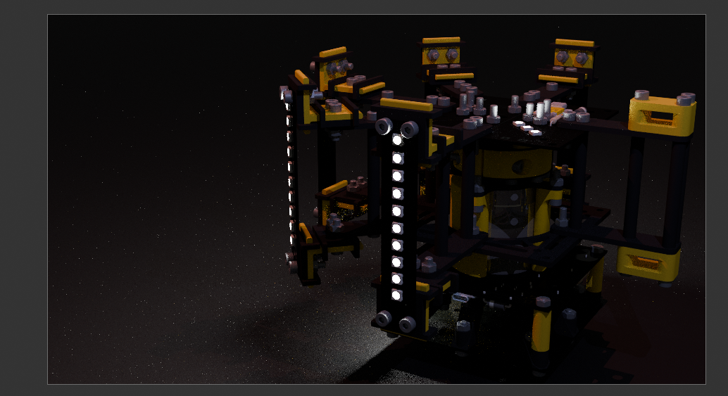
ok, gotta find out how to get some GPU to run this, since my tables getting really hot. pretty happy with the image already though! here's the full image...
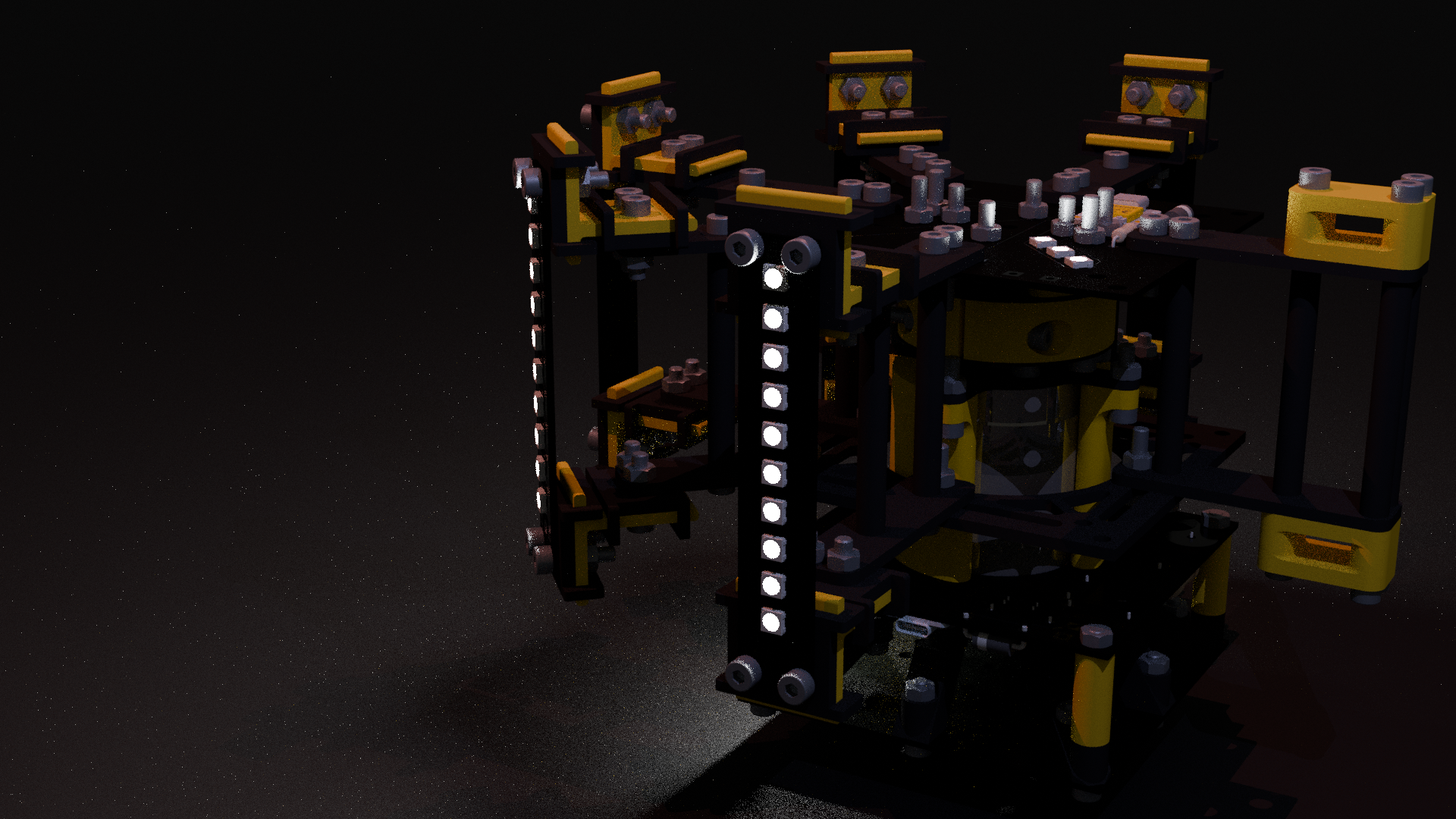
huh i guess google colab is the solution
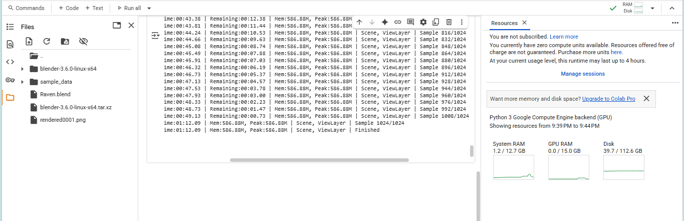
kinda upset that i didnt change the color of the XIAO (its yellow oops), but looks good! gonna commit to see if this works on github...
oh, it doesn't guess this might fix it? oh it did! ok, time to update the wiring diagram! (on paper, of course)
just read over the 4S overdischarge protection specs and it has a upper limit working current
of 10A, with bursts of 20A, but does that mean we can draw the full 20A? idk. not sure if we have to switch from our 288W to 150? i mean, it should have enough torque (in theory) to only require that much power intially (to ramp up?), which should really be the only draw spike? we range from 148-168W on 10A with 4 cells, and 296-336W on 20A with 4 cells. basically, should be fine? (if not, we can just make the mosfet pulse it)
ok, how do i wire the 4S 20A BMS now. uh it does not say. it does not (the 4S 20A version seems to be the only one thats square and weird, so i think i might need to find another one?) guess what, turns out 4S 20A on aliexpress is very unfindable (other sites exist, but for aliexpress, where where where). however, while searching for it, i stumbled upon this youtube video out of nowhere, and it looks fairly similar (same markings on the silkscreen), so it should be alright!
ok, 10:38 PM, wiring diagram done! just kidding, fixed some stuff, 10:47 PM, and the internets exploded, oh look its back
also, very important, i need to add little battery contacts/cases to the BOM!
woo! lots of writing, almost there! a bit more writing, need to remember to do cleanup! oh right, battery cases! whys aliexpress in spanish now. oh, found some!
ok, battery cases added, gonna commit and start cleaning stuff up! ok, deleted lots of stuff! also copied the gerbers from inside each PCB and pasted them in /PCB/GERBERS/!
well, almost there! gonna check the requirements once more! seems good! planning on releasing in a couple minutes! (once i update the journal, not gonna update in this file!) ok, just gonna reread all submissions stuff, this is gonna be released at 11:59 PM on 7/26/2025 to the public!
wow, what a journey! gotta tally up the hours... but yeah, learned a bunch, just kinda nervous for submitting (this was 100+ hours of work across 31 days, so its a lot!), but yeah! probably gonna go back to programming for the rest of summer (well, other than building this), so that was fun! ok, good night, and the next update log will contain stuff about building!
see ya!
Time Spent: 4.25 hrs
07-27-2025: Day 32: Submitting!
not really much!
surprise! didnt expect to see this huh? well, not really much today. basically, spent my morning looking through everything again, updating stuff, added another battery holder to the BOM (for the charger), compressed some stuff, and really just working on submitting and fixing stuff. overall, not too much work today, just a bunch of checking!
but yeah, havent really done anything for the rest of today (i guess thats what happens when you spend 107 hours on something and now are done
), so yeah, pretty sort update today, good night!
Time Spent: 2 hrs
07-28-2025: Day 33: Shopping
too many reciepts
dang, hack club is FAST! currently 5:45 PM, but the project got approved at like 8:32 AM this morning (as in NYC time) (yes, i was still sleeping at this time.)

(thanks cyao!)
anyways, just wanted to take a moment to see how far we've come! 31 days of work, research, and all, leading up to this moment. we're definitely not done yet, we still have ordering (gonna try doing that today), but we've done A LOT. redoing the PCB like three times, hunting down MOSFETs, and lots and lots of CAD. looking back, i dont feel like it was that much, but hey, i guess i dont see the progress so far? itll be pretty obivious when i see a giant thing in front of my face. (hopefully no one snatches the package off my porch.) ive decided what songs i want to do for the first tests. for testing (as in, the systems), i want to use the song thats meant for rainbow LEDs. yep, it's Caramelldansen (speedycake remix). then, for our first full test, we're gonna use the song that started it all, back in BattleCry 2025, I Slay. yeah, interesting choices, but that's gonna be it!
needless to say, im very excited right now, time to start ordering! surprise surprise, turns out we got a $20 JLCPCB coupon (thanks Hack Club!), so the PCBs are only $0.75 (wow!).
hmm do i want the order number on it? i guess ill just leave it as is, might look cool (i mean, looking at my hackpad, doesnt seem to be too big)
ok, checkout, here we go!
ew sales tax and stuff has made it $1.64. still crazy good though!

one down! gonna start working on a spreadsheet... ok, got a ordering list ready! next up, the microcontrollers!
so uh i have no idea if they ship with headers, i hope they do?
two done! lcsc next! uh is lcsc ok, everything adds to $8.99 but jlcpcb is saying $9.23? oh wait thats because its counting the discount later.
ok, LCSC done! $41.15 spent so far, off to dinner! (its 6:53 PM right now!)
back at 8:34 PM! next step is imr batteries! (im gonna do aliexpress last) ok, its 8:47 PM, and that's good! ok, four transactions so far, now for the final one! aliexpress! spent $66.60 so far!
just poked onto youtube to find something to listen to while working and suddenly got recommended a 13 year old GTX 680 video. huh. ok, aliexpress time (im terrified)
ok, we should use the welcome deal on the motor now! since its the most expensive component on our BOM!
ok, $17.65 motor dropped down to $3.59 ($0.82 added to both numbers since thats the little number below or whatever), selected the 288W 12000 RPM motor!
buddy.

seems like the solution (according to reddit) is to make a new account? HOW AM I SUPPOSED TO ADD A BILLING ADDRESS WHEN YOU DONT LET ME AAAAA
so had to reload page like three times, entered card info so much that ive kinda memorized it, in fact here it is, just kidding, not gonna leak the card info!
ok, aliexpress motor done, time for the rest... thats a lot...
uh oh theres only one set of 20pc 16mm screws left... i think i need to find another batch? gonna split the other aliexpress orders into batches of 5, just for safety
whys getting reciepts for aliexpress so hard, i just had to upload 8 files
looking for DIN912 screws... ok, heres some that have M4 16mm screws! a bit more expensive than the other ones, but at least we have them! ok, BOM would be $1.28 more, but we've been using so many of these deals, it isnt too much anymore
so uh. i seriously goofed up. i uh. forgot to add the AOD424 to the BOM. which is kinda silly, given the fact that its one of the most important parts in the entire system. (im very sorry)
ok, almost done with aliexpress. gonna wait until cyao wakes up or something, since i need to let my reviewer know about the BOM change (the screws). other than that, we're almost done ordering!
ok, prepared it for ordering tomorrow, gonna freeze the cards overnight (just so no one, you know, yoinks)
$239.94 remaining! here's what the transactions look like:
currently on track to have the entire BOM be $124.07! (assuming deal still applies tomorrow morning, and that i didnt forget anything else)
ok, so that's about it for today, what else is there? gonna go draw some art until midnight (its 11:32 PM right now), so yeah, gonna update the journal, good night!
Time Spent: 4 hrs