Macpad Keyboard
Total Hours: 23
Initial layout (2 hours)
I have researched Apple and apple clone keyboards.
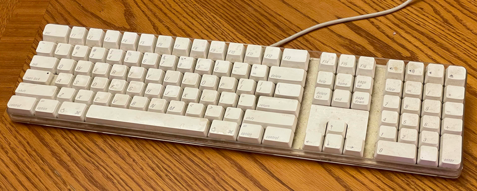
I will be baseing my keyboard off of this design with a few added features.
New features:
- USB-C power
- Mechanical switches
- Rotary encoders
- volume fader
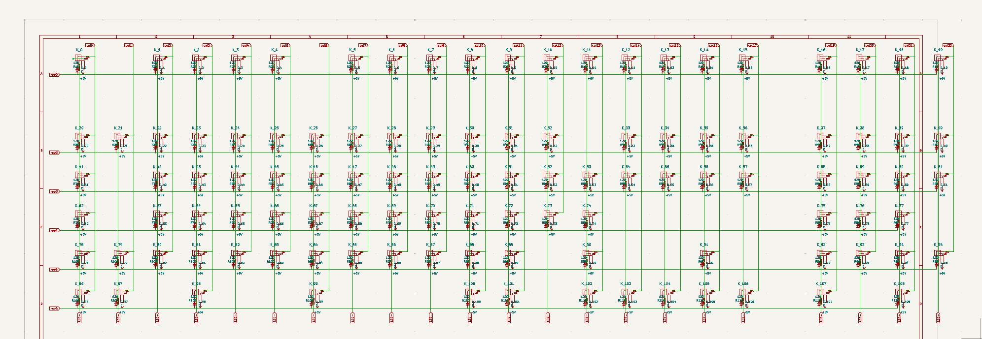
I started by mapping my keyboard matrix. I am using MX alps hybrid footprints to give a wider range of options for switches.
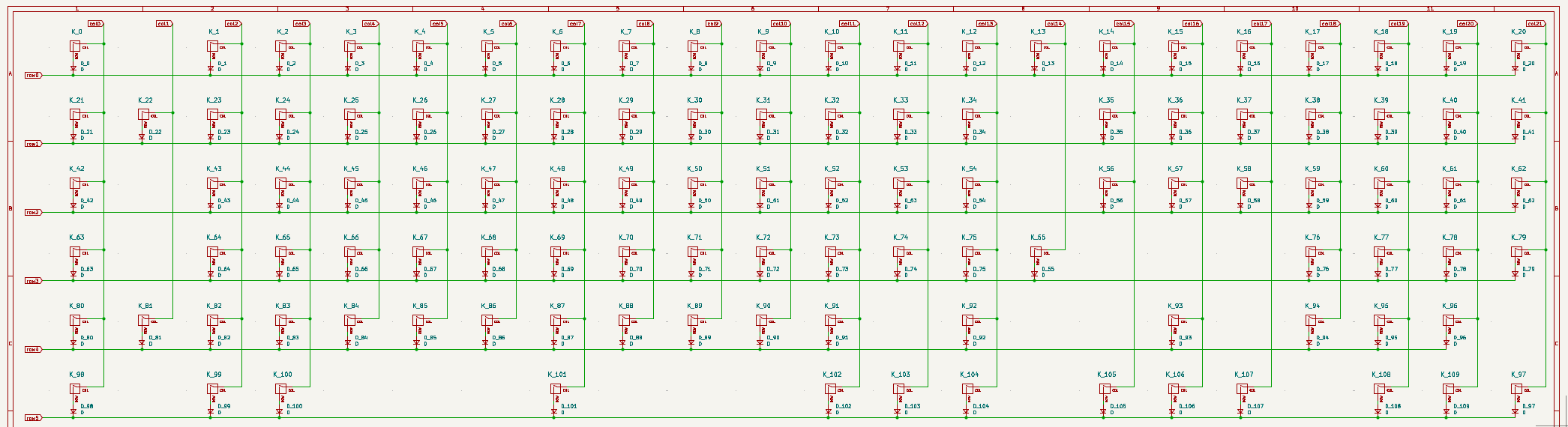
This layout closely mimics the original layout with few changes. Having that finished, I have begun to research QMK compatible controllers for the next step.
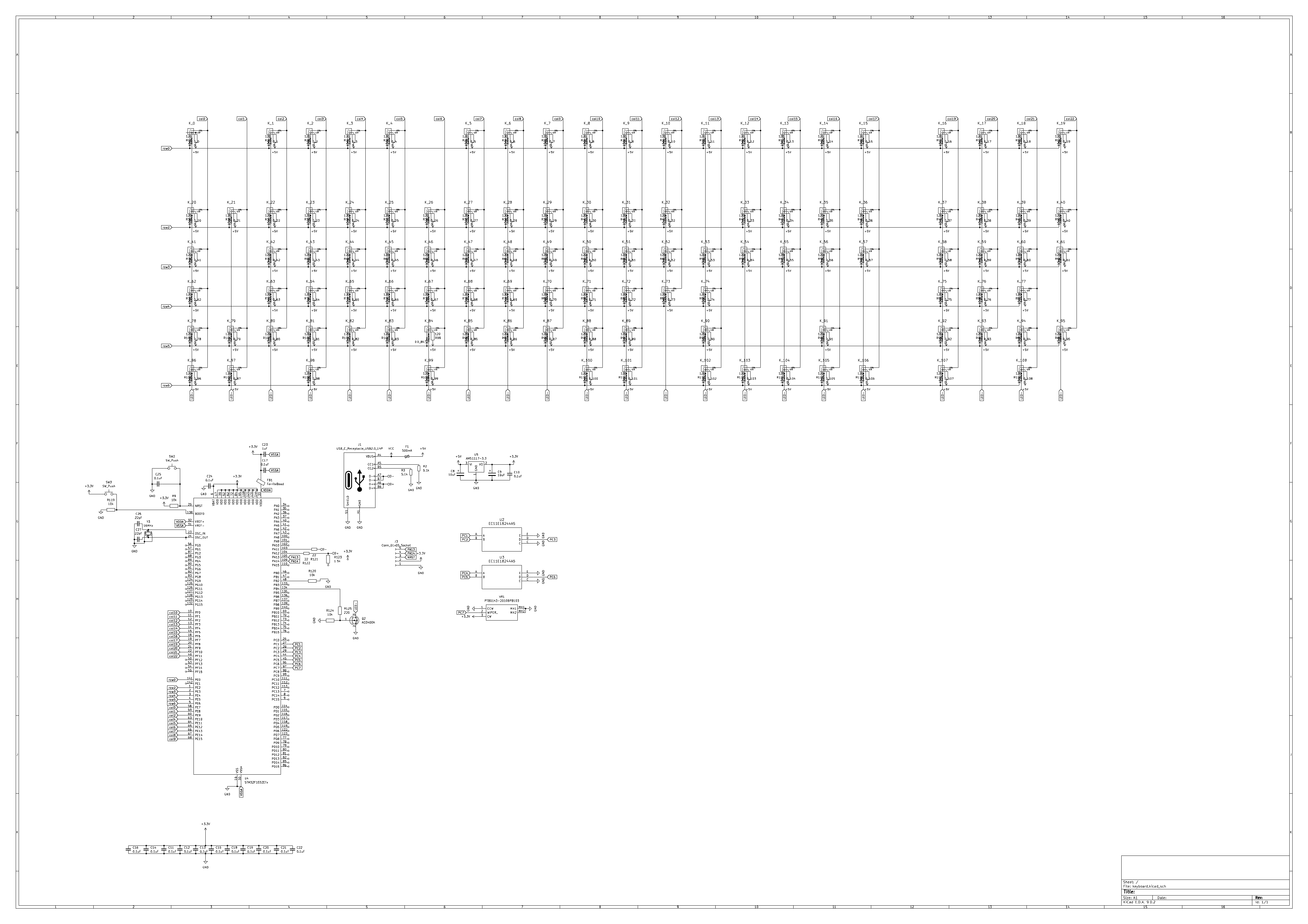
Microcontroller (2 hours)
I am using an AT90USB1286 controller (due to its USB functionality and QMK compatibility). The controller is connected to a 16mhz crystal for timing. The CC pins on the USB-C port are pulled down to ground via 5.1k resistors to follow the USB-C specification. I have 2 rotary encoders (EC11) and the special feature of my project, a fader for volume control. Capacitors 1 to 7 are used for decoupling and filtering.
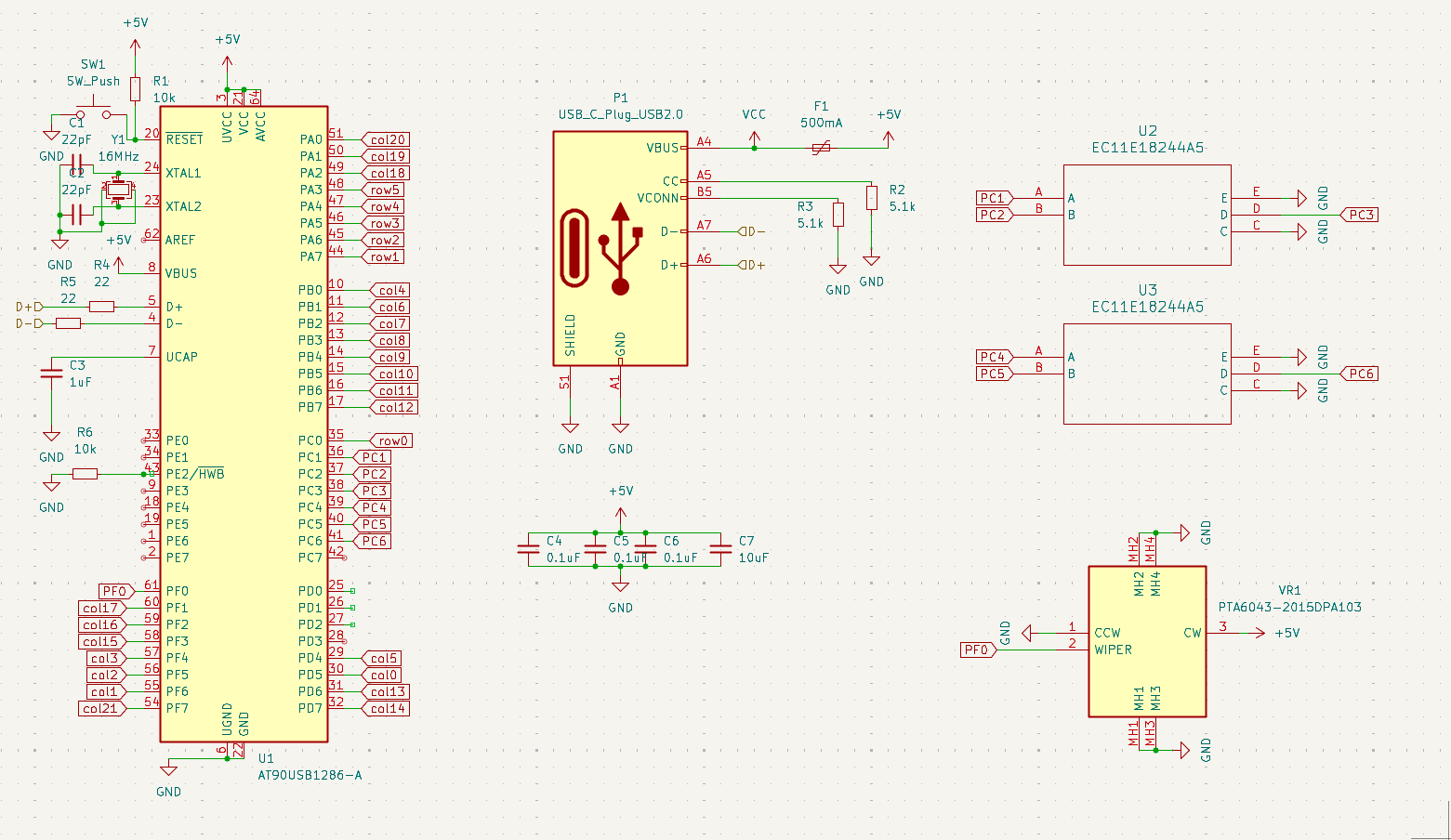
The columns from the layout have been connected here to the matrix above. I have also conencted up the two rotary encoders and the slider fader.
Layout (2 hours)
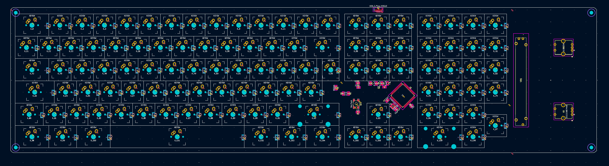
Next i laid out the keyboard in the most optimal format for the space. This format allows me to make versions with and without the fader + rotary encoders. I also rounded the PCB edges and added 3.2mm screw holes for mounting inside a case. I have ensured the pcb is less than 50cm long to ensure it can be assembled with many assembly services.
Back to the drawing board (2 hours)
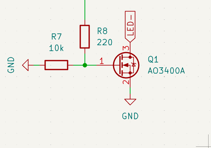
Due to using a non standard layout, I found it would be impossible to get keycaps for some keys (such as my thin iso key). I am instead using a more standard layout. Because of the saved money from doing this, I can now add LEDs. I have added a backlight led matrix that can be controlled via the MCU. I have created my new layout, connected it to the MCU schematic and added LEDS with a driver.
New Layout (2 hours)
I laid out the PCB again with the new logic for the LEDs.
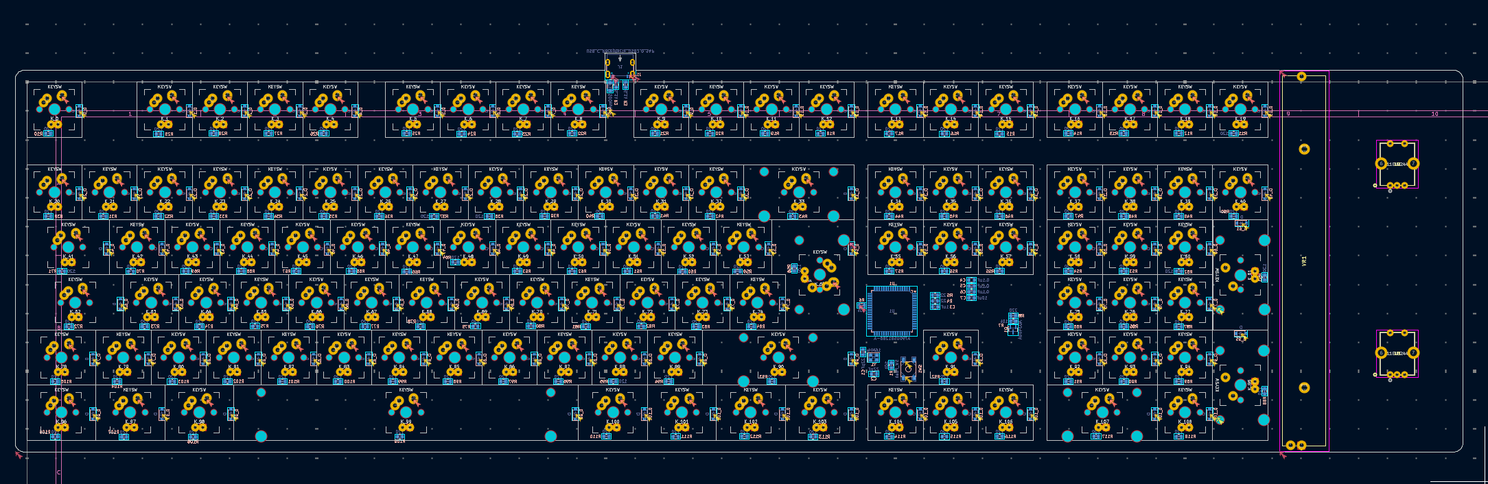
I have added a resistor to 5v for each led and laid the pcb out similar to before.
Routing (2 hours)
I routed the PCB and added a ground plane.
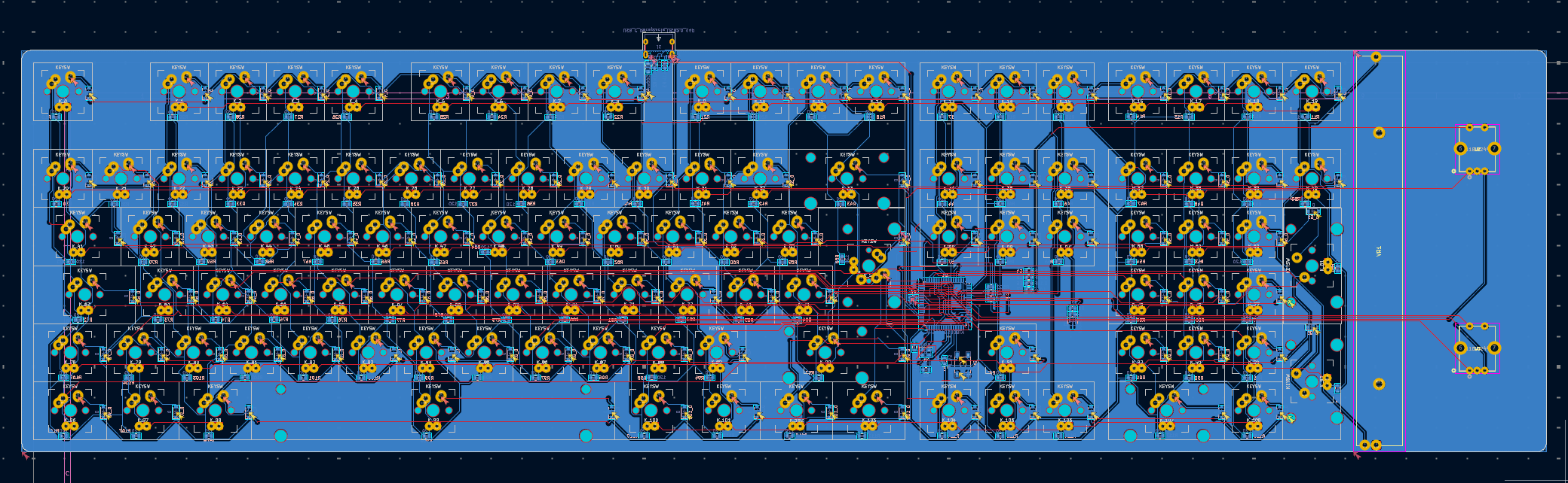
Although my ground plane is missing from a large part of the PCB, it still links all ground traces together well. I also added 4x m3 screw holes for mounting.
Plate (1 hour)
Next I created a plate for my keyboard. First I created my schematic in KLE and used a tool to convert KLE to SVG for the plate. I then matched this up with a plotted version of my pcb silkscreen. I then drew the full border, added holes for mounting and added holes for my special components.
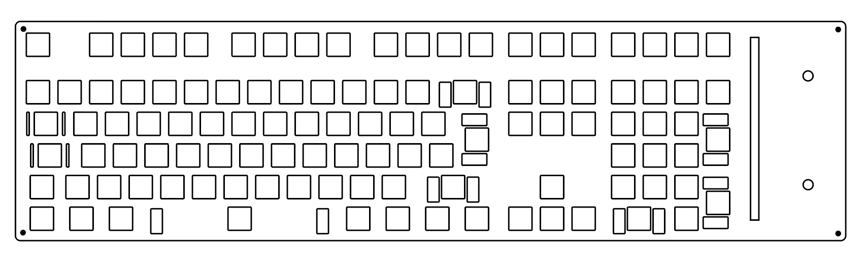
Next I will begin to design a case for my PCB.
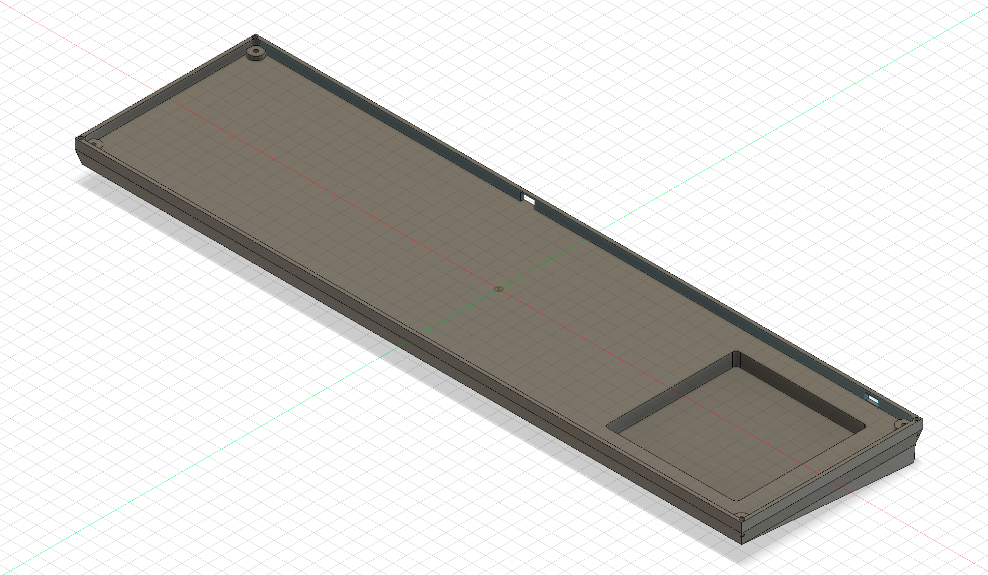
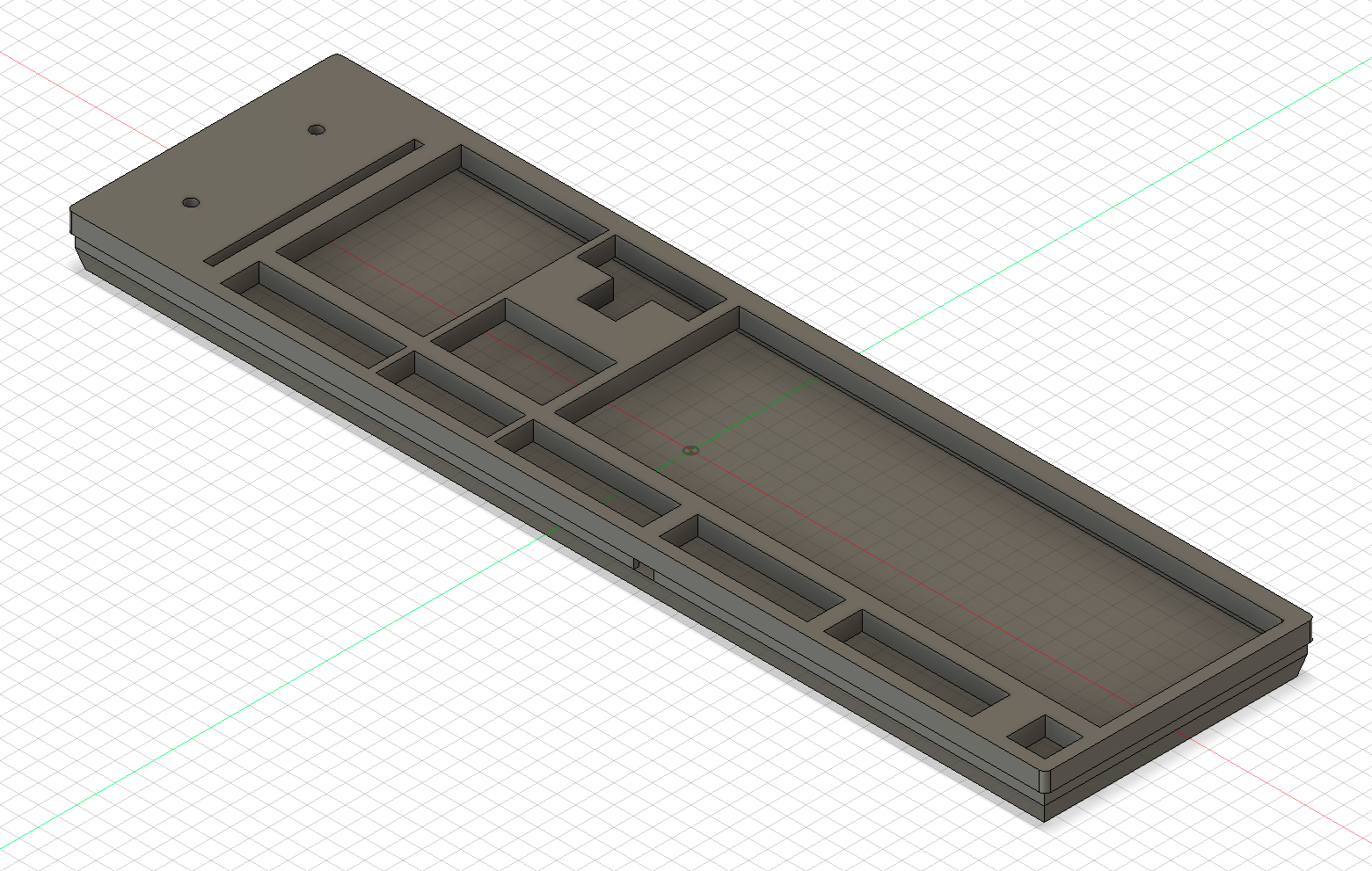
Case (1.5 hours)
I designed a case for my PCB My case fully fits my USBc port and will fit my PCB with plate. This case can be 3d printed in 2 parts and is assembled with m3 screws.
Firmware (1 hour)
I mapped the keyboard in QMK and added the hex file for flashing. I also swapped the backlight and a column pin to have them on the correct pins.
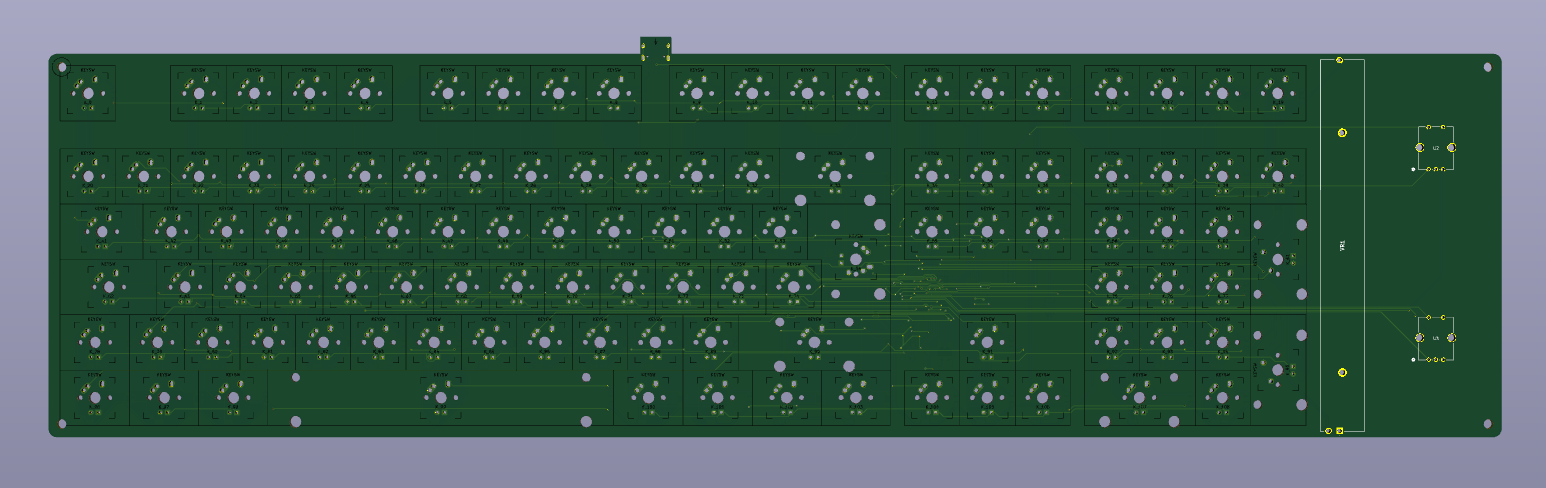
Polishing (1 hour)
Added a render of the PCB and case together. Rounded some edges on the case. Added holes for rubber feet.
New controller (1 hour)
I have replaced the controller with the more readily available STM32F103ZETx due to cost.
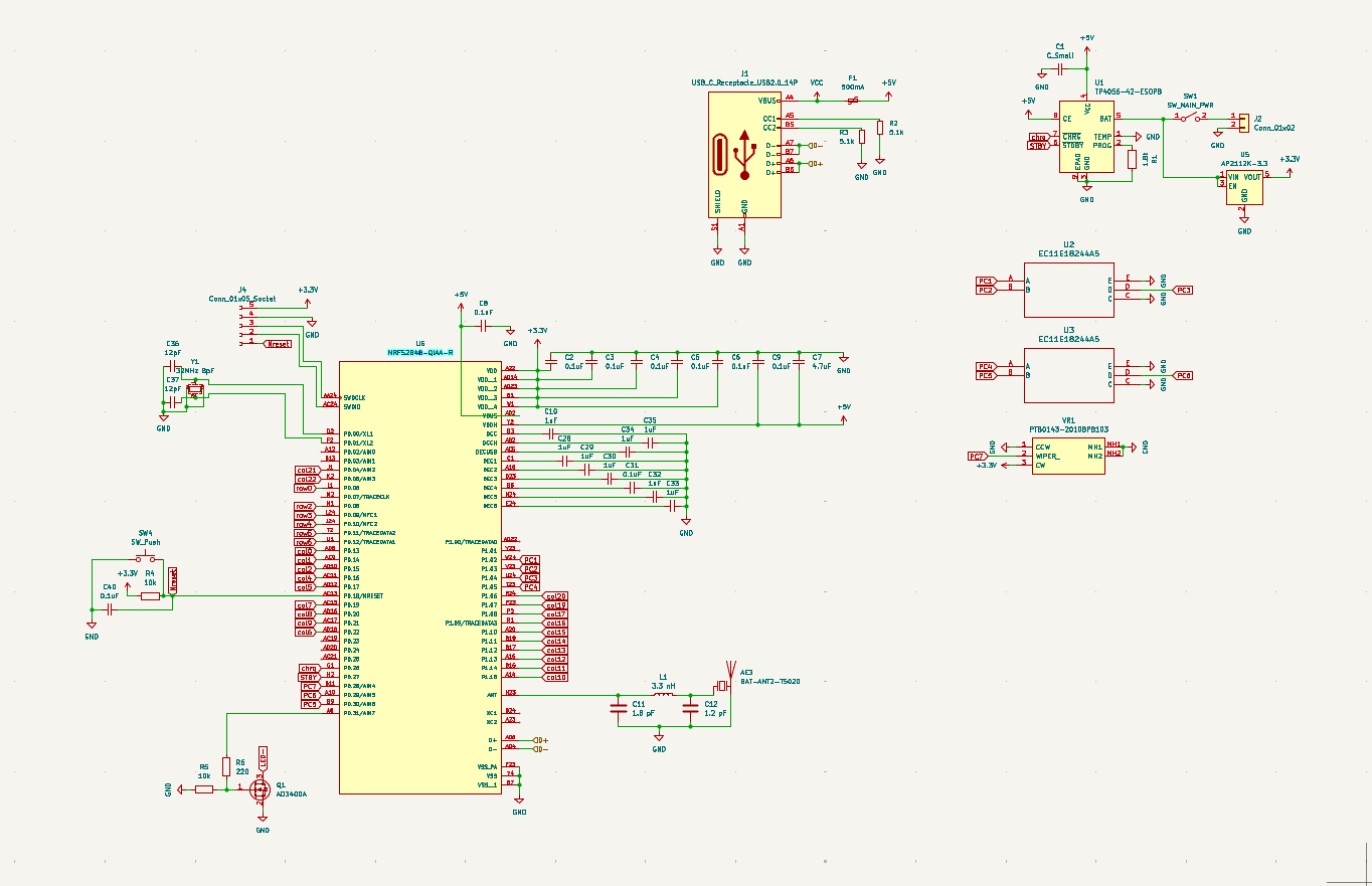
Bluetooth and Battery (2 hours)
This involved finding a ZMK compatible bluetooth chip. I chose the NRF52840-QIAA-R as it is a commonly used chip. I then wired this int he same way as my previous STM32. I am using a 3MHz crystal and have designed a Pi network for my antenna using (in theory) optimal values based on the data sheet.
I have also added a TP4056 battery controller and a 3.3v regulator for battery power to allow wireless use.
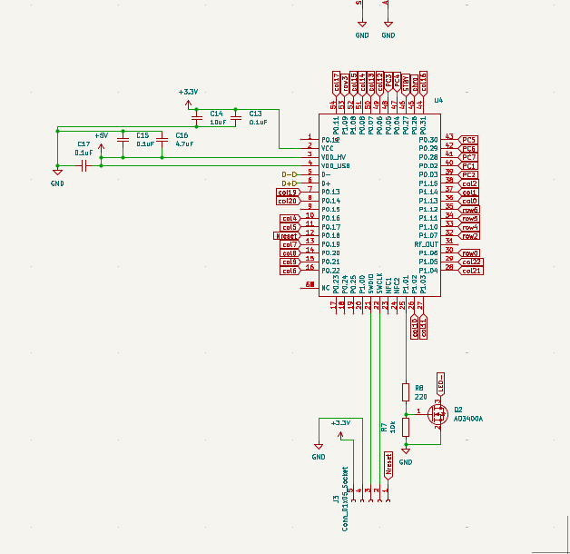
Attempt 3 (2 hours)
Unfortunately i was unable to route the antenna circuitry without printing the board to perform initial tests so i am instead using a RF-BM-ND06 System on board. This makes my design more simple and more reliable. My schamtic now has bluetooth and battery power implimented.
Routing (1 hour)
Routed the PCB after laying out the components again.

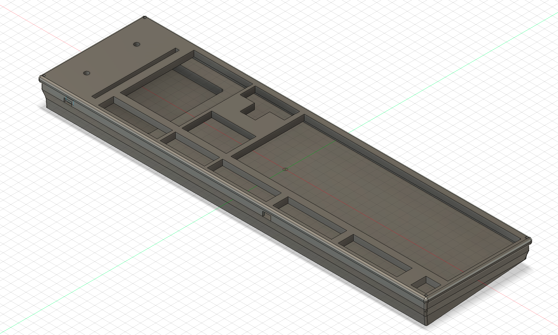
Case (0.5 hours)
I extended the depth of the case and added a lot to make room for the battery. I then added a hole for the SPST power switch. The battery hole is of sufficient size for any size of battery and an adhesive backing to be chosen.
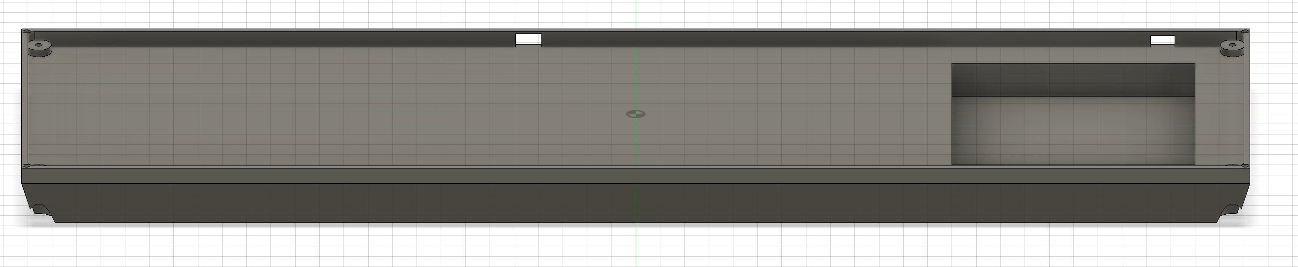
Case (0.5 hours)
I fixed the issue where the screw holes come out the bottom, I also added a slanted base to allow it to sit at a 5* angle. The case is also thinner now to make it easier to print. I also rounded the internal angles in the battery comparentment corners for fun. I have added the inserts for 10mm rubber feet onto the slanted bottom again. I also rounded the outer corners to make the keyboard easier to carry.