
Aluminum CNC Mill
Fixed gantry style CNC mill that's designed to mill aluminum and small steel parts!
Day 1 - Brainstorming
On the very first day, I set out defining the goals I wanted for this project and actually learning about the pain of making a CNC I'm going to go through.
Here's the main criteria I wanted for the machine: - At least a 40cm x 40cm workspace, perfect to machine literally 99% of things - Cost around 300 USD, so it's affordable for me and others - Be able to mill aluminum, plastic, wood and mdf - Be decently small and contained - Easily repeatable for others - Easily assemblable because I had very minimal tools
The 300 USD budget is very ambitious but it's something I thought was really important, because I feel like the whole point of making a CNC machine is to make it budget friendly for anyone anywhere.
I found a lot of really good resources like the Infill page which details how to make a 3D printer and I feel like 3D printers are directly relatable to CNC machines.
This taught me about the basics of a CNC machine: - Having a frame - Rails to guide the axes - Something to move the axes like ball screws or something - Spindle
I had a good idea of what a CNC machine was actually made with by the end of first day.
This day probably actually took like 4 days but I'm just simplifying the days down to each like section. I know it doesn't look like much was done, but it's very complicating just jumping into it. Total time: 8 hours.
Day 2 - Defining my CNC machine
On the second day I needed to define what I was actually going to build, I had already created my main constraints but now I needed to think about actual parts.
From a bit of searching around, I found that Nema 23 or higher were needed for a much bigger, rigid machine that could mill aluminum. I found a steal of a deal on facebook marketplace: 3, Nema 23's for just $50!! I quickly copped these steppers because I knew these were what I had to use for budget and rigidity purposes.
The next part of this day was figuring out how to build a strong frame but for cheap. I quickly realized that I didn't have many tools to cut steel or anything, so it was important that it was easily assemblable. This led me to Aluminum Extrusions which were cheap, rigid, and could be used to easily assembly the frame and add rails and whatnot.
I was still very confused about what type of extrusions, 30mm, 40mm, 80mm, I had absolutely no clue and no idea what style to make them.
Something I did decide on though was a fixed gantry style CNC mill. I made this decision for quite a few reasons: - The Y axis can be controlled by one stepper motor and uses less material because a fixed style needs to have decently long, very rigid steppers on both sides of the machine with longer ball screws and more expensive parts used to make it work. - It's a very rigid and efficient design that will maintain strength but also be decently cheap still
Using all this information I created my first drawing. Drawings REALLY helped define what I was building and were probably one of the most important aspects of building such a crazy machine. This is a basic drawing I did in Krita:
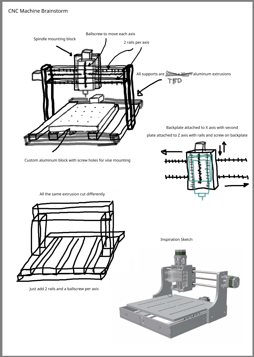
You can see that the frame is purely made out of aluminum extrusions and bolts which make the frame pretty cheap and easy to assembly because I can just order the extrusions to size and with the specs I want.
Total time: 12 hours
Day 3 - Collecting my thoughts
The big thing I wanted to do on day 3 was to get my thoughts down and actually to start working on a CAD design.
I knew I wanted to create the frame out of aluminum extrusions but I still wasn't sure what type of aluminum extrusions to use. This is where Tom Stanton came in clutch. His series on building a CNC mill/router was a massive help to me, because he showed the full general process of building exactly what I wanted to do.
I noticed that Tom Stanton used extrusions that had 2 slots in them like this.
 This gives lots of space to add rails and connect segments, while maintaining a very high level of rigidity. I still didn't know where to order them from though, so a quick google search later and I come across Misumi. I couldn't believe that I could get 4040 extrusions that were 400mm long for just 10 USD and I could fully customize them!!!
At this point, I'm pretty sure these are the extrusions I'm going to go with, but I still want to keep the price cheaper so if I somehow come across something cheaper and as high quality I might go with that.
Now I still wanted to actually get something on paper, so it was time to do a bit of CAD work. I've decided to use Onshape for my CAD because it works in the cloud so I can still work on this in school and I'm used to using it for other projects. I might switch to Fusion360 though if it gets too laggy, but we'll see.
I'm not used to creating huge assemblies like this in onshape, more designing parts so I referred to ChatGPT really quickly on how to create an organized workspace. I figured out the easiest way would be to add in the DXF's of things like extrusions, then create part studio's for all the sub-assemblies like the aluminum extrusions. Each sub-assembly would have like the different sized of extrusions like 400mm long, 800mm long, ect. And I will probably end up doing this for all the different parts like linear rails, ballscrews, etc.
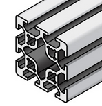
For the end of this day, I finally got something into my CAD workspace and it's so cool to actually get something on paper though after 10's of hours of brainstorming.
Just 2 simple aluminum extrusions but it's really exciting to see something actually on paper.
Total time: 16 hours
Day 4 - working on the frame and revisions
I knew this day would be a bit slow because I was starting to put some stuff on paper and making many revisions to my vision.
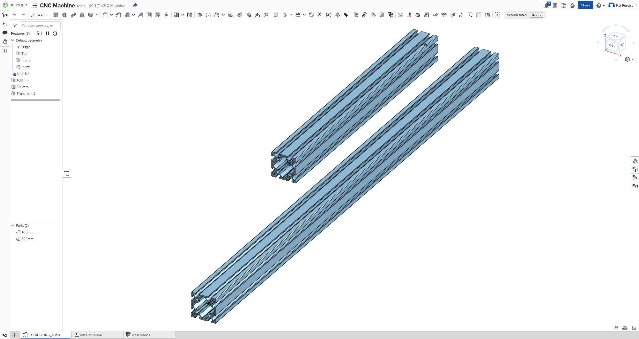
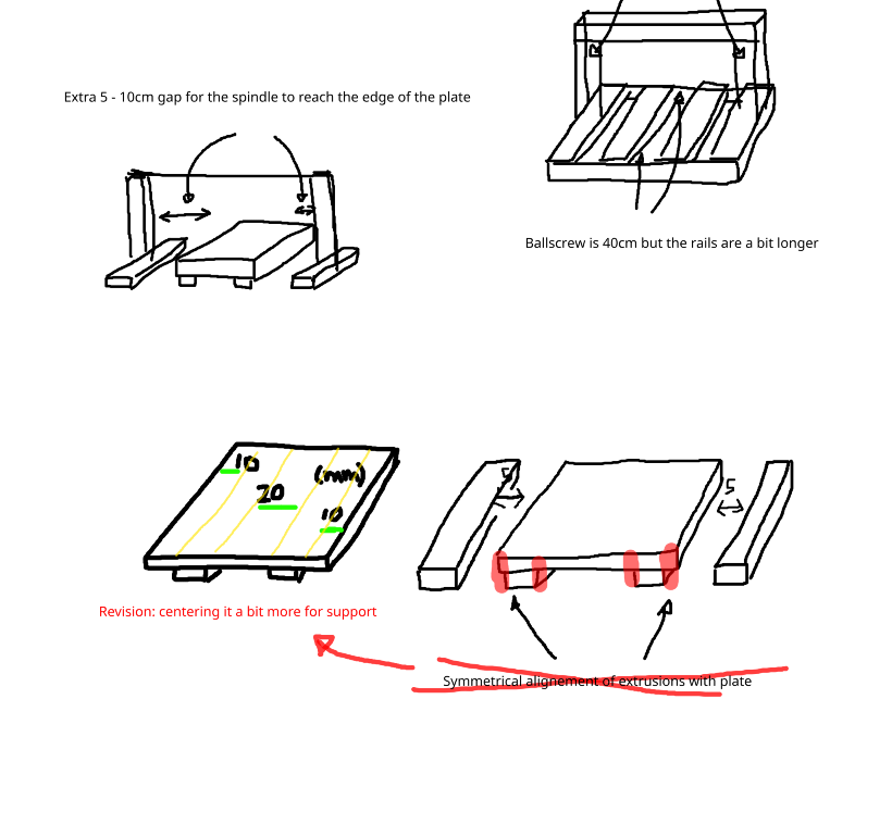
The first thing I wanted to get down was some of the base frame calculations. I needed enough space for the fixed gantry for the spindle to be able to get every part of the 40cm plate. This means that I would need 20cm of space on each side of the plate, so I decided I could probably leave the ball screw at 40cm leave (which I feel like I'll regret late) and make the rails longer for support. If the ball screw attaches to the plate at the center, this should give it a full 20cm in each direction.
I also knew that the spindle couldn't reach the farthest side of the plate because it's a big chonkier so I needed to have a little bit of space on the sides. I decided that about 5 - 10cm would suffice.
With this in mind, I started to design the base of the frame. I decided that 500mm extrusions for the sides and 400mm extrusions for the supports would work nicely and give me enough space.
But while putting together the extrusions, I noticed that putting the center extrusions flush with the side of the plates reduced the rigidity because there was less space in the center which was where a lot of the weight was, so I decided that fixed the inner extrusions more towards the center would increase rigidity.
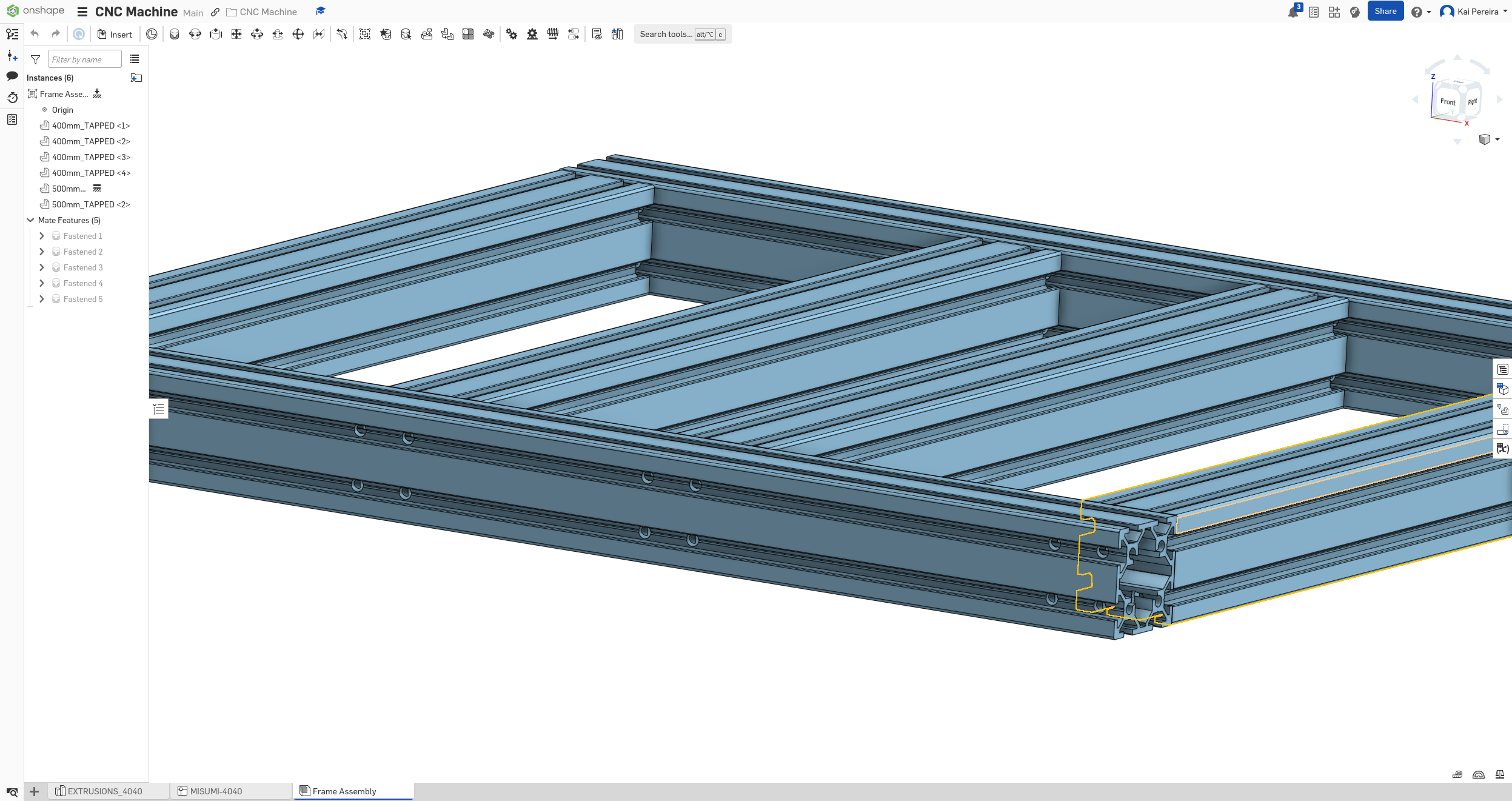
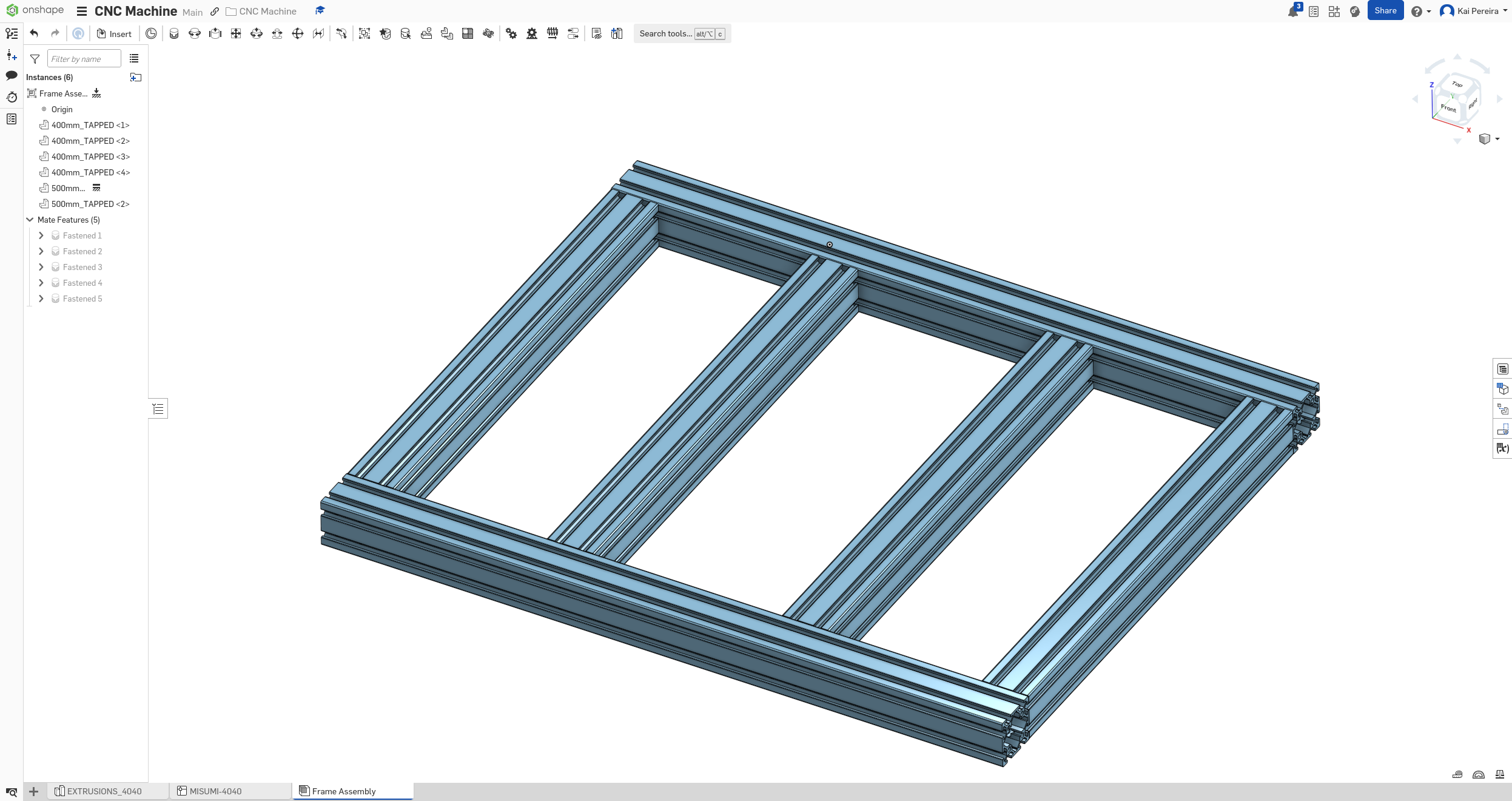
 Now I modeled everything into Onshape using these revisions and calculations, and created a basic base frame.

This base will be rigid yet compact and leaves enough space for spindle to hit everywhere on the plate. I still feel like I need to center the extrusions a bit more, but I'll see when I put the plate actually in the CAD design.
I want my CAD file to feel like literal instructions for building this so I might turn away from the frame for a day or two so I can actually CAD the bolts and stuff that will connect the extrusions.
Time total: 18 hours
Day 5 - Disaster and Progress
This day made me some reality checks and I also made a lot of progress. The main focus initially of this day was to get fastening of the joints down into CAD.
I had absolutely no clue how to fasten aluminum extrusions and the internet actually wasn't that helpful. So I did some deep research and decided that a bolting with T-Nuts would be the easiest option.
This process is a bit complicated to understand at first, but it's fairly simple: - Tap both ends of the 400mm extrusions - Screw in bolts and T-Nuts into the tapped ends - Cutting holes that match up with the T-Nuts into the 500mm mounting extrusion - Slide the T-Nuts into the 500mm mounting extrusion - Tighten the bolt to create a very solid mount
So I added the holes on the mounting extrusion and this is where some things started to go downhill.
I've realized that I want to make the machine mill 40cm x 40cm but my extrusions are only 4cm. I thought 4cm was a decent amount but I took a quick look at a measuring tape and realized it was pretty tiny.
I also realized I completely messed up my frame calculations, just how big the mounting extrusion is going to be and how much extra space I'm going to have on the sides. So this means tomorrow I'm going to have to spend a lot of time doing re-calculations and more research.
I really want to be able to mill aluminum, so that means the design needs to be RIGID, but I also want to be able to mill 40cm x 40cm, so I feel like I either have to make the working area of the CNC mill to be smaller, or make the extrusions bigger.
I still want this to be very budget friendly though, and making the extrusions bigger, increases the cost quite a bit (nearly double), so I'm going to have to think of a smart way of solving this.
I could use 4080 extrusions, or maybe use like mounting brackets to make it stronger, but I'm not too sure.
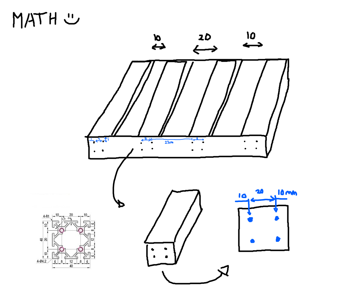
Now time to make some more revisions. First off, I redid the calculations (this is probably my favorite drawing so far):
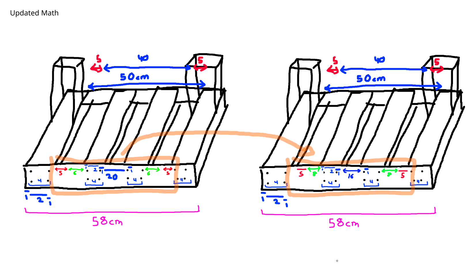 I now have an accurate frame with 5mm of error on each side, and keeping maximum rigidity in the center of it (which is the second revision of the drawing)
Now time to put update my CAD design! I keep on messing up my calculations because my drawings are from the edges of the extrusions instead of the middle of the holes, but after a couple tries I got it down. much more rigid now!
Now I still might actually put them closer together, but I'll take a look at it once the rails are actually on it. For now, I want to research if I need larger extrusions and I want to get the T-Nuts and bolts into the design.
Total time: 22 hours
Day 6 - Rails and T-Nuts
I know I wanted to use T-Nuts/Bolts to bolt together the extrusions but I wasn't quite sure exactly what T-Nut to use. I'm not an engineer, so I assumed all T-Nuts were the same... But I never realized the insane variety I could get.
T-Nuts come in tons of different forms: - Drop in spring balls - Drops in after assembly and have a ball bearing - Double or triple T-Nut plates - multiple threaded holes - Threaded Rod T-Nuts - have an actual like long thread that can tighten internally - T-Nuts with stud - which come with a threaded stud - Slide in/Preload T-nuts - insert before closing off
Here, you can be apart of the pain it is to find out what nut I need to use for this project:
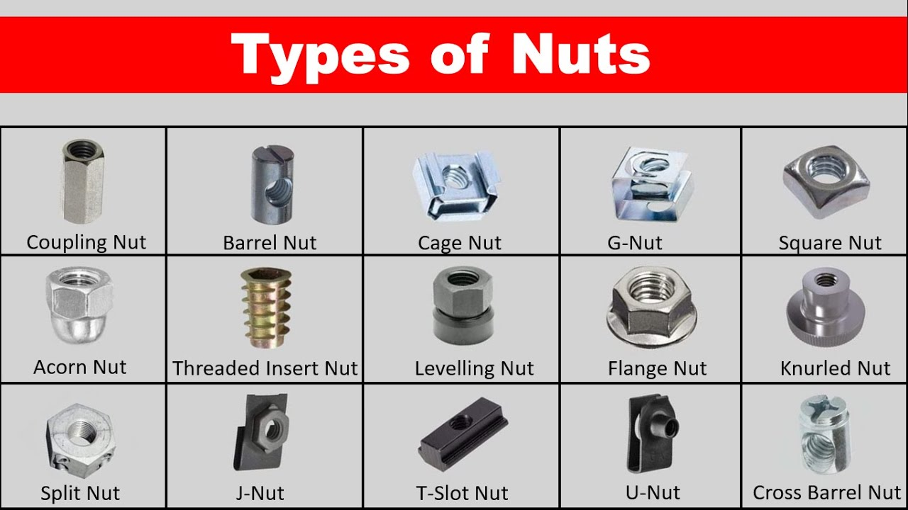
I'm not an engineer so I had NO CLUE what to use, but T-Slot is the move!
I decided on using the slide in T-Nuts because I can attach them to the bolts and then just thread them through the extrusion and they're the cheapest ones while being extremely rigid.
But I actually might re-consider this decision because of how many T-Nuts I actually need. Tom Stanton has been a big help to visually see how to make a CNC mill, and I noticed he just uses threads to hold the extrusions together. This approach might actually be cheapest because you can just buy a threaded bolt and it would probably be cheaper. I definitely need to research this even more!
Because I started to go insane, looking at the pro's and con's of T-Nuts, bolts, etc. I decided to start looking at linear rails. Boy did I underestimate the pain this would be. Again, this CNC mill needs to be around the $300 range, but I did not think that a long piece of metal, with a rail attached would cost me $50!!!! for ONE. I needed 2 for each axis, so 6 of these.
This was a huge problem and I need to get my prices down. But thank god aliexpress is alive, I could easily get 500mm long rails for $25. But I still didn't know what type of linear rails i needed.
I thought there was only 1 type of linear rail, but nope, there's 3 major ones for CNC: - Mainstream linear rails - just a block of metal with a rail with bearings - Rods - a circular rod with bearings or bushings to move it along the rod - V-Slot wheels and rails - literal wheels to travel the extrusion allowing motion
I knew that V-Slot wheels were probably out of the equation because they weren't rigid enough and it would be weird to fit them onto my extrusion that had 2 rails on each side.
So the decision was between rods and linear rails. While I feel like rods could work, I have seen next to no CNC Mill use them, and for a good reason: - Looser fit - Wear down pretty fast - a bit bulkier/larger - Noisy and flex quite a bit - Low point of contact
So I'm probably going to use linear rails because on aliexpress, I've seen them for decent prices and I think I can get it down to maybe like $100 for all the linear rails. Costs are adding up FAST! With the stepper motors I've bought, that means I'm already at $150, but I would nearly have the frame completed, I would just need ballscrews really which I estimate are going to be like $75 or so.
But I still don't know what type of linear rails to use, the market is so flooded with chinese products, it's impossible to know what to use. A bit of a ChatGPT session later, I found out that the cheapest and most reliable rails are going to probably be MGN12's or higher (the 12 refers to the width of the rail). The thing is, the MGN's have lots of copycats on aliexpress that use the same specs, so I can get decently reliable rails for a good price on aliexpress!
The thing about ordering rails on aliexpress, is they come with anti-rust grease most of the time, so something I learned is soaking the rails in isopropyl-alchohol to remove the grease and then lubricating them so they work smoothly. This will ensure they have a long lifespan and are much more reliable, because lots of people think that the grease is actually lubricant.
Now that I kind of know what parts I want, I really want to research like the exact rail I need, because there's plenty of different lengths, widths, etc. Once I have this down, I really need to put the rails into my CAD drawing (I can probably find a good MGN rail model on grabcad) and add the T-Nuts in too.
I really want to make sure my CAD drawing is extremely precise, so I make little to no mistakes when building the actual thing irl and costing myself more money.
Total time: 25 hours
Day 7 - Rethinking rails and rigidity
After putting down my thoughts on day 6, I realized that maybe my frame wouldn't be rigid enough. This was kind of a fear of mine that I didn't want to face, because this would mean rising costs and rethinking some stuff. I really want to mill aluminum on a decent scale so I need a LOT of rigidity and I'm not sure if 4040's can provide that. I'll put this on the back burner a bit and do some rails and ball-screw stuff.
While looking into where to buy my MGN15 rails, I came across lots of resource that said that MGN rails will NOT CUT IT. I did a bit more deep diving, and turns out they're really only good for light CNC like plastic and 3D printing, so I definitely needed to change this out.
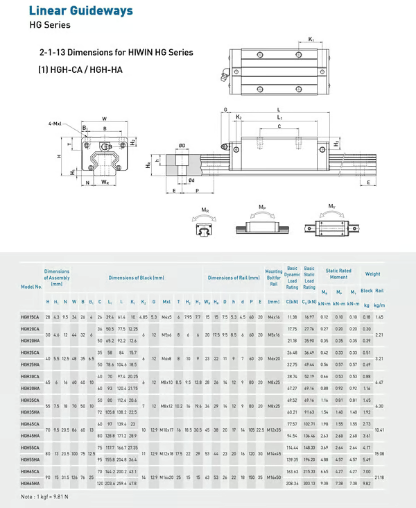
Taking a bit of inspiration from the PrintNC I think I'm going to use HGR15's instead. These provide WAY more rigidity and will definitely be strong enough and are even rated for steel. Not only that, but these will actually strengthen the frame even further which relieves some of my thoughts about rigidity. It's also pretty much the same price as MGN15's for some reason...
There are 4 different types of HG rails though, if you want to read about them, check out circuitist: - HGR is the rail only - HGW are carriages with flanges and wider hole spacing. - HGH are carriages without flanges, taller than HGW. - HGL are carriages without flanges, as tall as HGW.
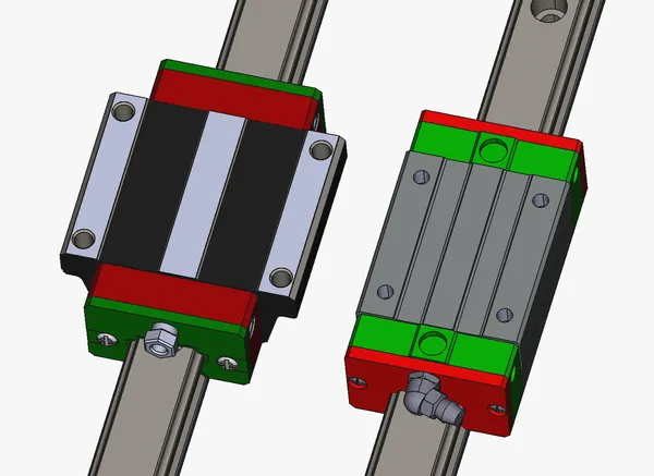
HGW vs HGH carriage
There's tons of weird naming conventions, but I found that Limo Bearings has some pretty good prices for them (but this is definitely still subject to change)!
Tomorrow, I'm pretty sure I can choose which rails I want to use and finally put them into my CAD design.
Now let's go back to talking about rigidity. I was browsing around in the PrintNC discord and I kept on seeing that people suggested using steel to mill aluminum, because it's nearly 4x AS RIGID in many cases!! While I definitely still want to use extrusion for ease of assembly, I'm definitely going to consider maybe some steel parts like panels on the side.
I also really want to consider using a mix of larger and smaller extrusions in weaker and stronger spots. This is a really cool DIY CNC mill design I found in the PrintNC discord (I forgot who it was from though).

The things I really like about this are they use larger extrusion on the sides and smaller extrusions for the rails which is very cool. They also use a steel frame around the whole thing, which I could imagine is EXTREMELY strong and combined with the steel side-panels, it could probably mill steel. But honestly, I could always consider building a CNC mill with only extrusion and then consider upgrading it with steel parts once it's finished.
Based off my current specs, it's definitely convincing to switch to a 30x30cm baseplate but I'm determined to make 40x40cm work. I really want to be able to mill things like keyboards at a max and 40x40 just seems perfect. I'm honestly probably going to use this idea of 2 larger extrusions on the side and 2 smaller ones inside with rails on them.
Tomorrow I feel like I'm going to get the rails in my CAD design, look into steel parts (and how easy they are to work with) and maybe re-do/think about the frame.
There's so much to think about when it comes to a CNC mill, and I really have to consider a multitude of things and just keep on re-iterating to make something incredible and affordable.
Total time: 27 hours
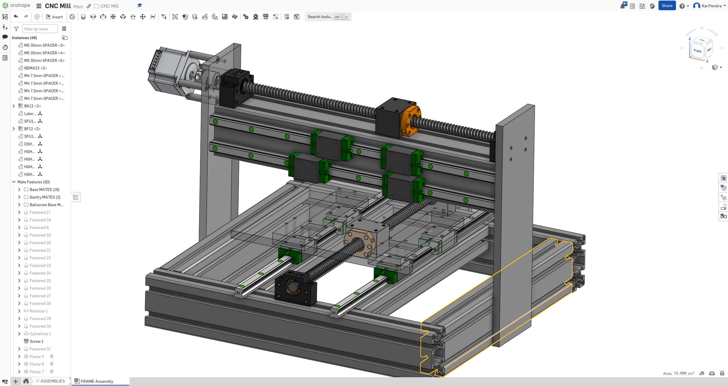
Day 8 - CAD, Math and rails
I really needed to get some stuff into my CAD design after doing so much research on T-Nuts and rails.
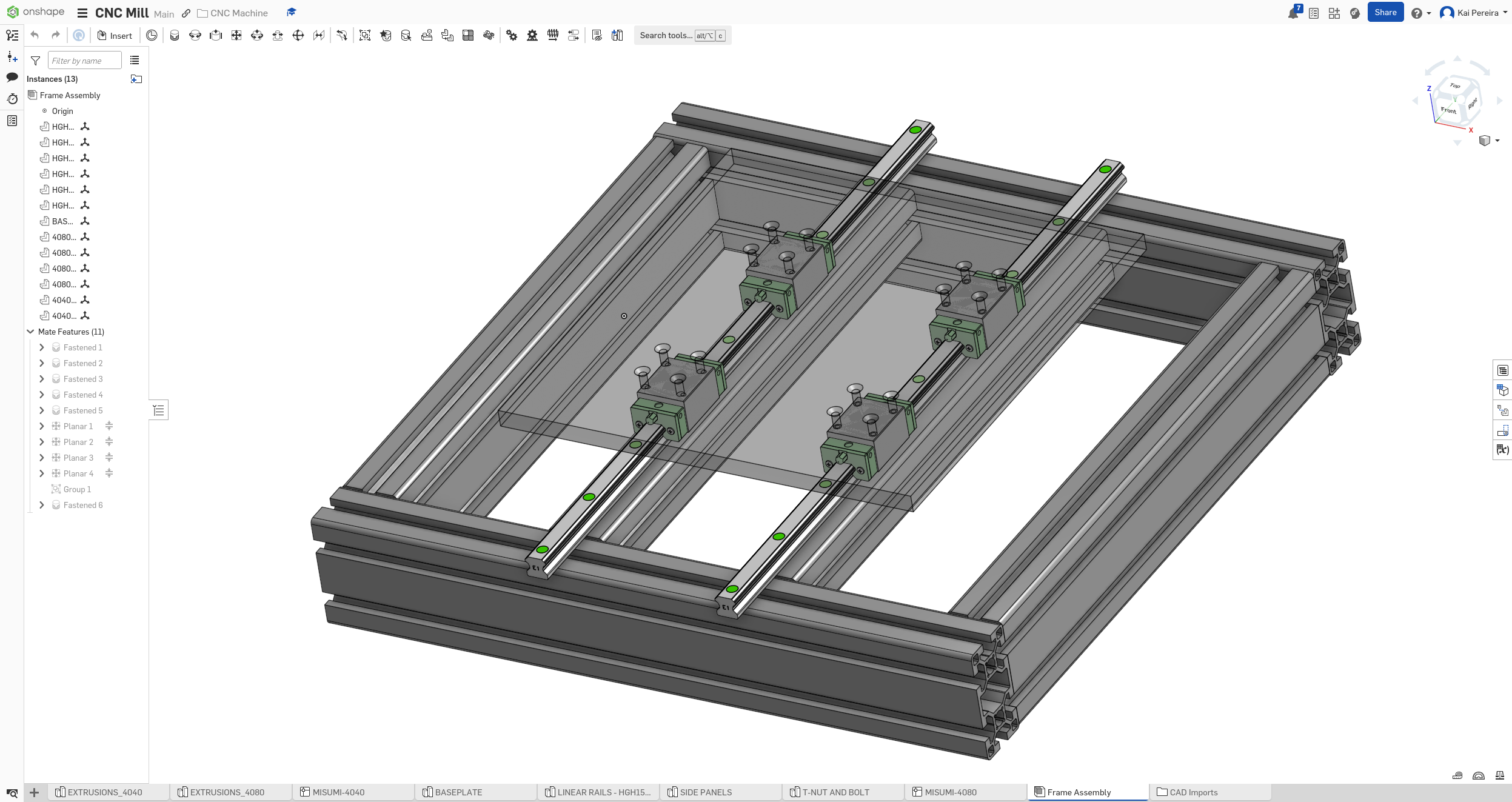
I decided to go with HGH rails because they have the highest price to rigidity ratio which is exactly what I needed. They're decently tall, very rigid and will definitely be good for this project. It's really easy to mount rails like these into the extrusion because I can just directly screw them in.
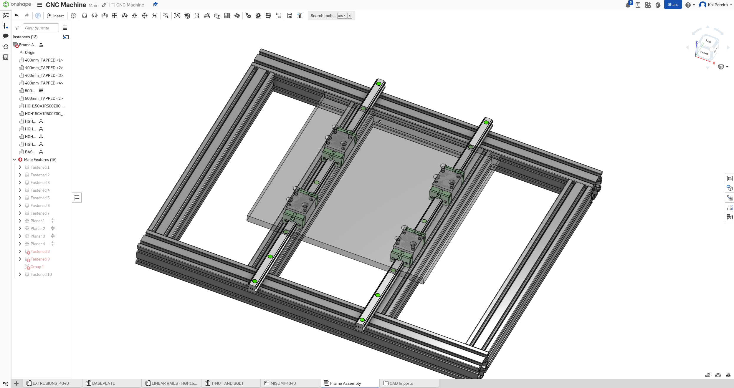
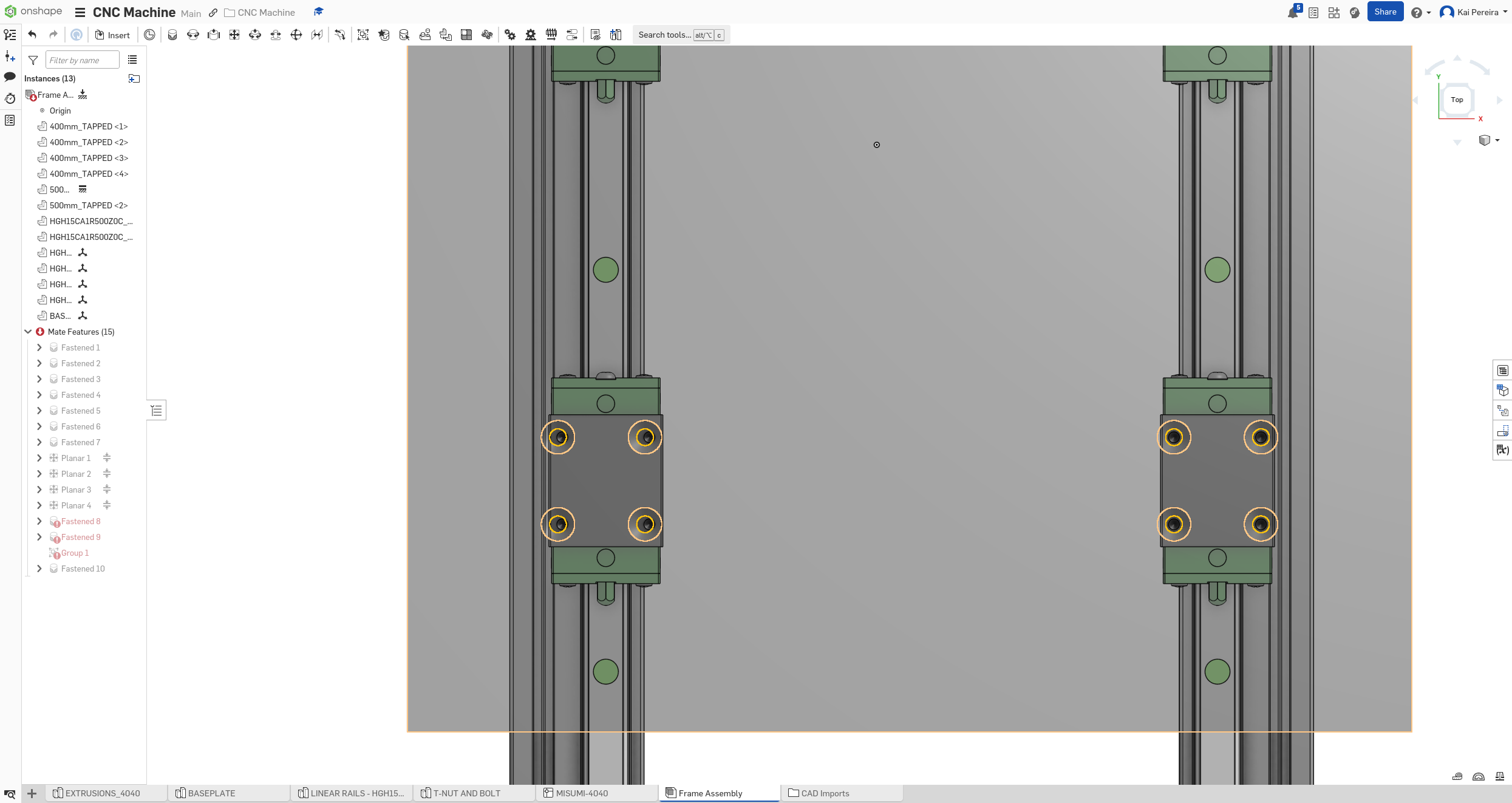
I'm really bad at CAD so it took a bit too long, but I got the rails into my design. I couldn't directly fasten into the extrusion slot because it was all at an angle, so I mounted the rails to the face and then offset them to be the center of the rails on the extrusion from looking at the specs on misumi for the 4040 extrusion.
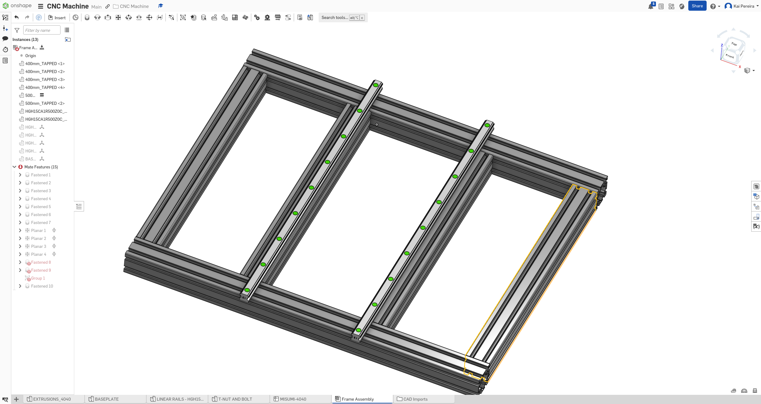
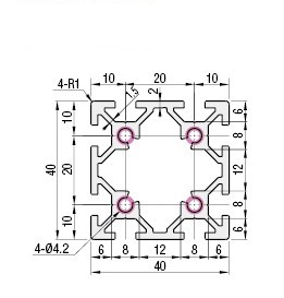 You can see that I chose to mount them to the inner rail of the extrusion, this is because I want to evenly spread out the weight along the plate to give maximum rigidity. I still feel like the rails could be even closer to the center, but instead, I might actually just increase the size of the bed to offset the inner weight.
I found the CAD design for the rails directly on Limo (which I'll probably end up using to buy the rails), and this included the rails and the carriages.
Because the CAD design included both the rail and carriage, I had to import them separately into the assembly from my document (they came as 2 separate different parts in my part studio).
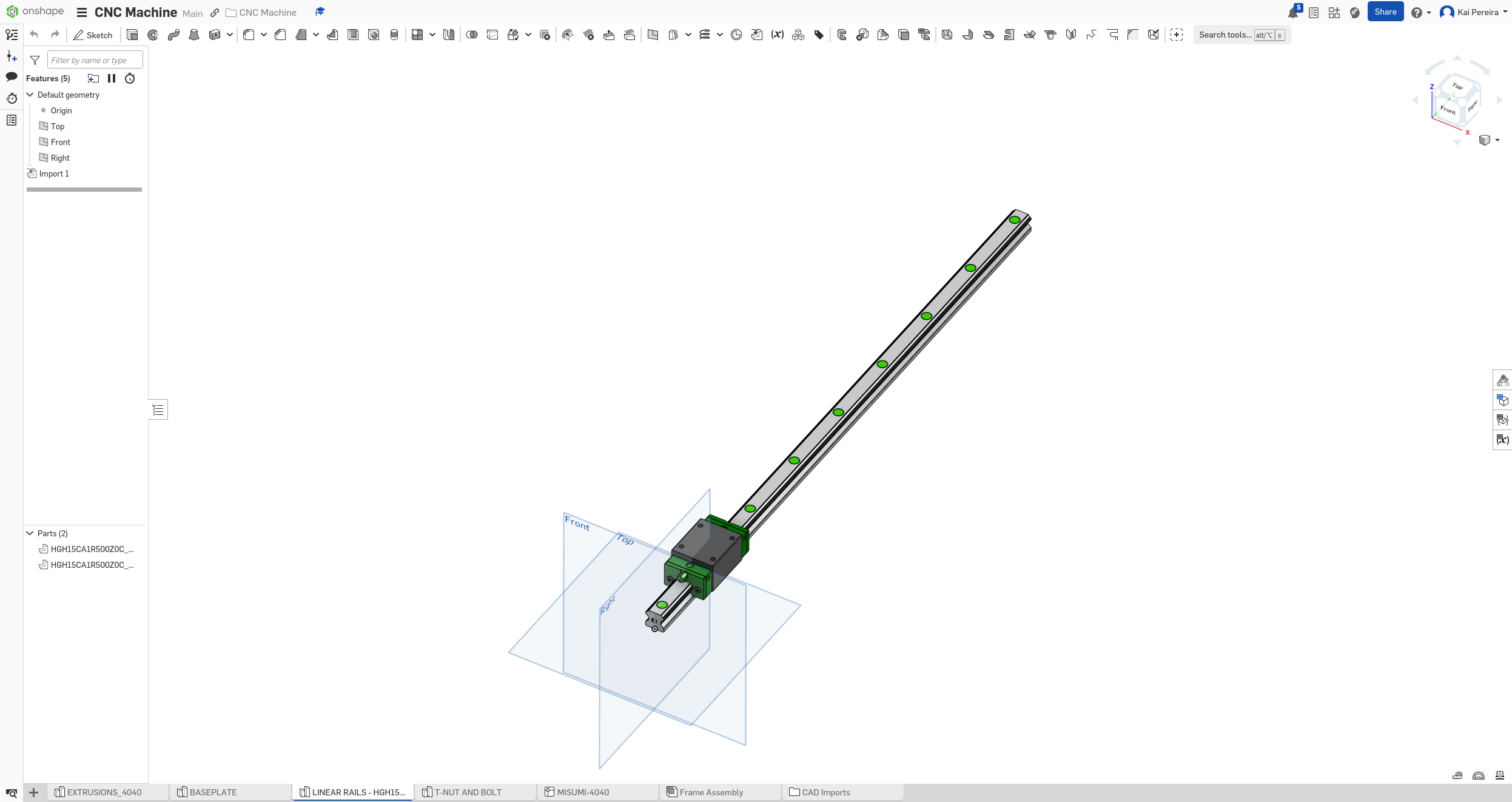
I then added them to the assembly by using a combination of planar mates to be able to move them along the Y, a fastened mate with an offset, to put the perfect distance between them, and then I grouped all 4 rails after offsetting them so they slide together.
I did some really annoying math using the carriage and the dimensions of the baseplate to properly align them.
Next I added the bed into the CAD design. I'm heavily considering switching to a 30x30cm work area for rigidity which I know wasn't my initial goal but I feel like it's for the best. It gives nearly 2x the rigidity and will have a way higher likelihood of milling aluminum at a good rate. I might be able to sneak in a couple cm too along the X or something but I'll see.
Because I'm really considering making it smaller, I designed the baseplate off 30x30cm dimensions. I did all the annoying math and put the screw holes so there's enough clearance for them to fasten to the rails. I also put a chamfer on the top of the holes for the screw head.
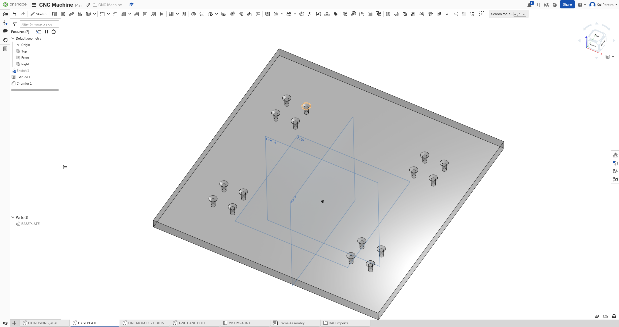
Then I simply mounted it using another hole for reference using a fastened mate and now we have a fixed gantry.
While this all looks pretty good, there's LOTS OF PROBLEMS, here's a couple: - Enough clearance for the screws and the proper space for a clean chamfer. - The rails probably need to be longer so the mil can touch the middle of the base-plate along the Y axis - Slight misalign of the screw holes for some weird reason (shown below) - Proper bed thickness and dimensions for maximum rigidity and screw depth - Proper frame dimensions to accompany the new bed size of 30x30cm
(weirdly aligned screws)
So tomorrow, I'll probably work on fixing all these issues, because I CANNOT have too many issues when I'm assembling the whole thing. Costs add up FAST. I also maybe want to do some sponsorship outreach (which might be better for the weekends). But aside from that, my CNC mill design is really coming together, it's definitely hard work, especially because of the fact that I'm not an engineer and in school for 6 hours a day :(.
Total time: 30 hours
Day 9 - Adjustments and research
I added a lot of stuff to the CAD design yesterday, but a lot of it was added in a sloppy way, so I really needed to clean up my design.
The main problems/errors I had were: - Screw clearance (which I thought was probably good, I'm probably going to come back to this later) - Too short of rails (which was definitely a problem) - Misaligned screw holes (another massive problem) - Proper bed thickness (definitely still an issue) - Frame dimensions for the new 30x30 bed (definitely an issue too)
I felt like I could comfortably ignore the screw clearance because I know I'll probably come back to it when researching all the proper screws, bolts, t-nuts I need and whatnot so I didn't want to worry about that right now. I definitely needed to get these other issues fixed though.
First I focused on the rails being too short. I had 2 options of fixing this: - Increase the length of the rails, affecting rigidity, possibly having to make the machine larger - Decrease the distance between the 2 carriages on each side, maybe affecting rigidity
I decided to go with the latter because the rails were only about 1cm too small in total (on both sides). This means, I'd only have to decrease the distance between the 2 rails, by 1cm which doesn't have a massive impact. I'll definitely be running simulations later to test how strong this will actually be though.
Because the center of gravity was a bit wack on the bed now, I decided to increase the side of the actual plate to offset some of the stress put on the center of the bed. So now the bed is 35x35cm which means the bed will be approximately 5kg, which will give the machine some more heft and rigidity.
Fixing the screw holes was pretty easy (but a bit annoying). I re-calculated the whole positions (with the new carriage placements too) and it seems work well. There still seems to be a tiny offset though which is a bit bizarre, I think it might be because of mistakes with the model, but I might revisit it, if I deem it a problem later on.
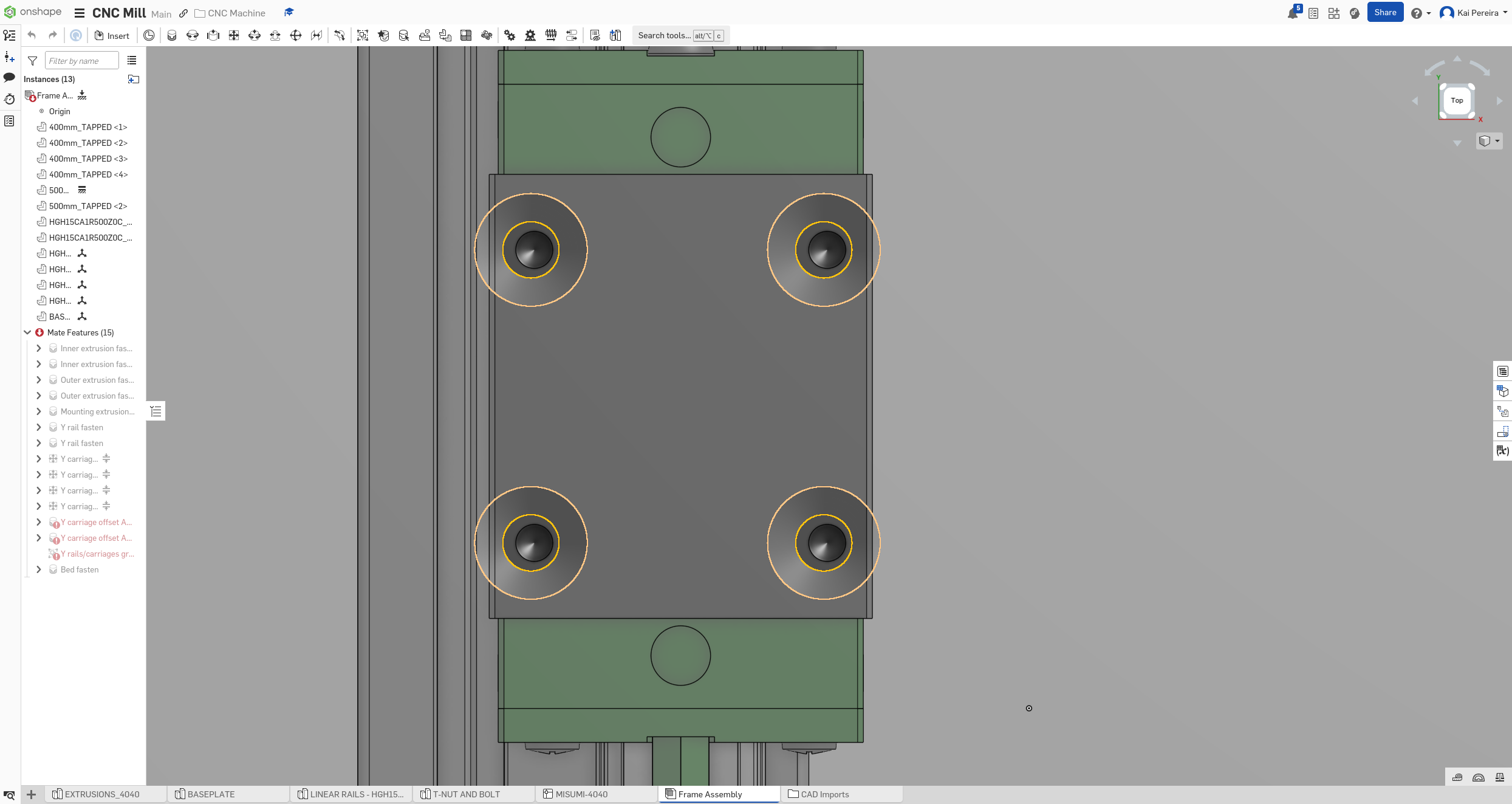
Straight on view of the weird holes
Because I was making the work area a full 10cm smaller, I could comfortably decrease the width of the frame from 580mm to 480mm, which will give a big boost to rigidity and make my mill much more capable of milling aluminum and giving it long-term strength. I honestly think this decision is for the better, and will probably save me time, money and pain.
Now the mill was looking much better and much stronger, I increased rigidity, fixed many small errors and made some good progress. I'm still really horrible at designing as this is my first major engineering project I've worked on.
But now, I needed to work on some pressing matters. The X and Z axis. I always wanted to do a fixed gantry style machine, because I knew that supporting the whole gantry on rails and ballscrews would need to be horribly rigid and cost lots of money in the process.
With a fixed gantry style, I could just mount sideplates and then attach the gantry, being very rigid. The thing is though, you can't create the side plate out of anything. Extrusion probably wouldn't cut it, being the gantry is a lot of weight, and the extrusions will probably bend underneath the sheer pressure of a mill.
So I have a few options for the side panels: - Multiple, rigidly mounted extrusions on the side - Solid aluminum plate with drilled holes (pretty thich) - Solid steel plate with drilled holes (maybe welded?) (less thick than aluminum)
I'm still debating what to do, and I need to look more at the pro's and con's of each, but I feel like extrusion might not be an option. I feel like it just doesn't have the rigidity to support the most important part of the CNC mill, and it'll probably be quite pricey to make it work.
A Chain Is Only as Strong as Its Weakest Link
The problem with working with aluminum and steel though is I'll probably need to drill custom holes, and have a custom sheet cut to what I need it to be probably like so:
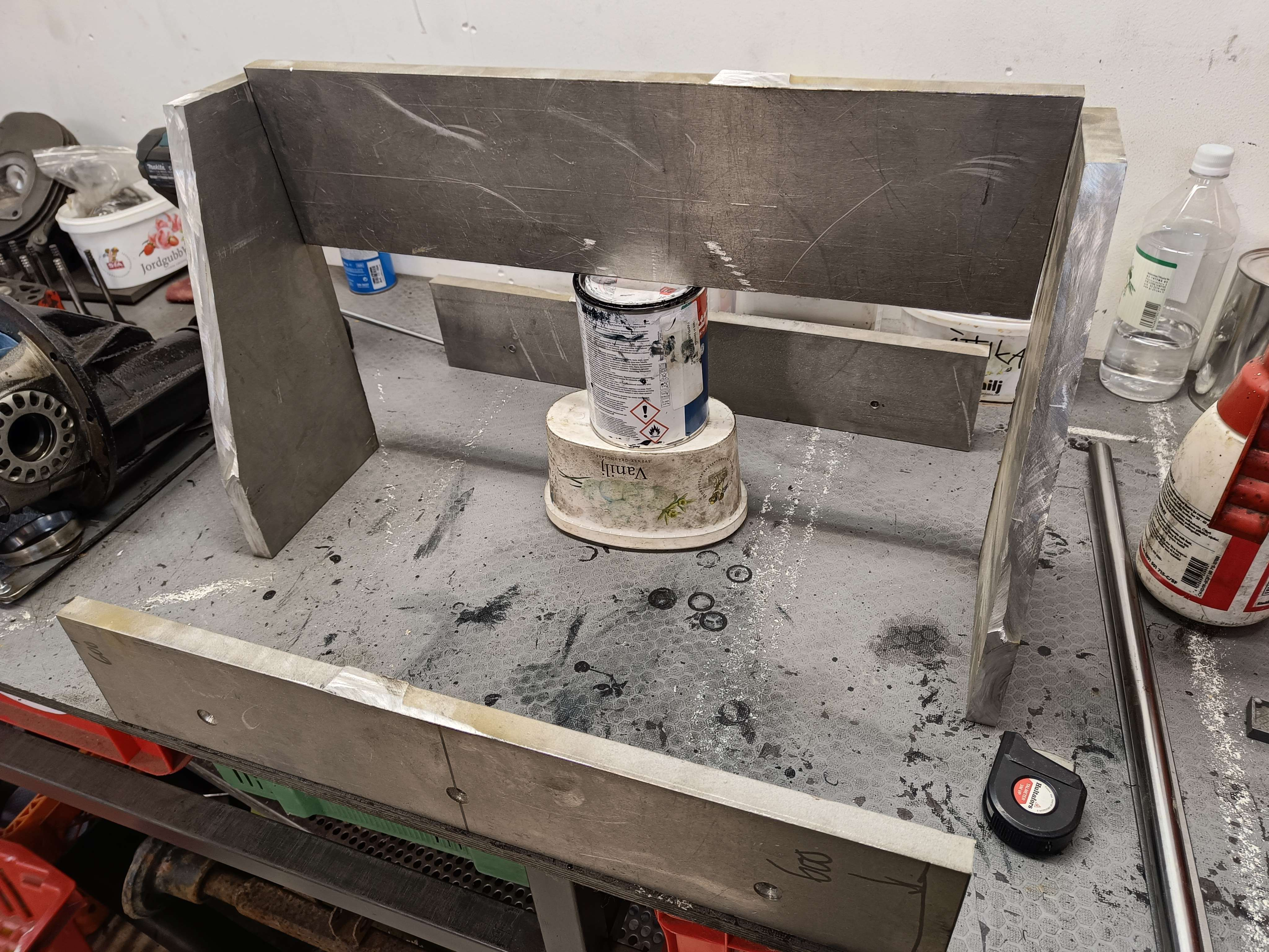
But this gives an insane level of rigidity, and I could definitely mount another slab on-top for the X axis. Tomorrow I'll look into more options for this, and I also want to take a look at BALL-SCREWS!!! I didn't get too much time to work on but I still got a solid amount done!
Total time: 32 hours
Day 10 - Reinforcements and side plates
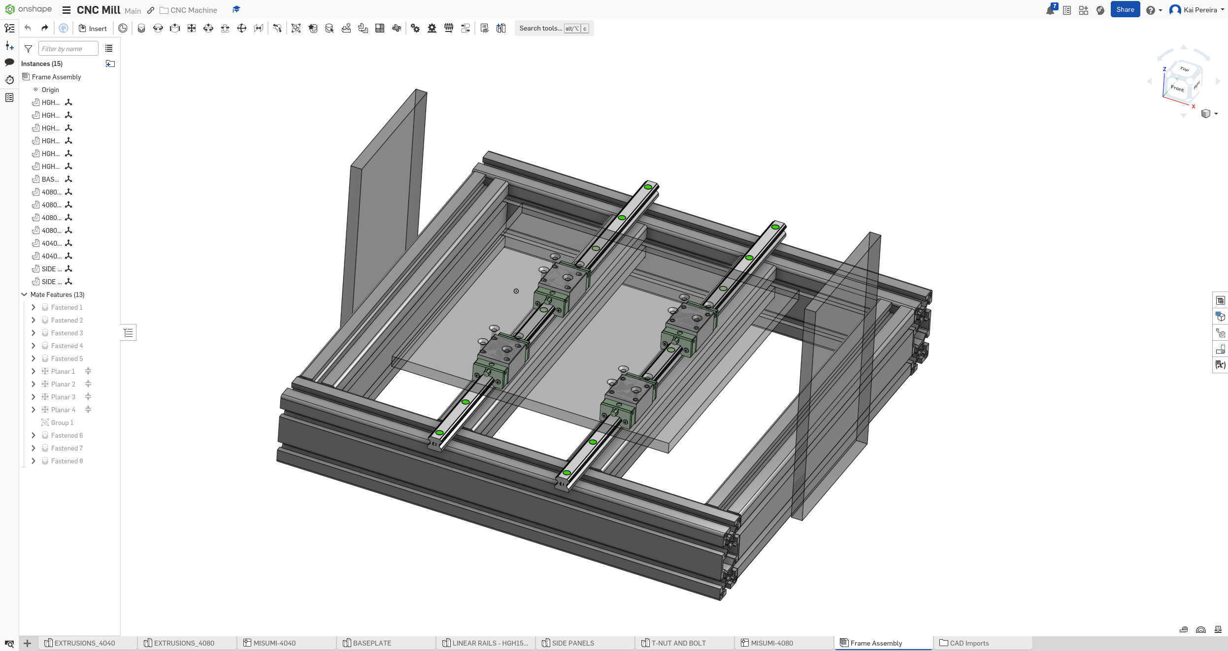
I've decided that it's definitely better to go with a 4080 frame vs a 4040 frame. I want to modify my layout so it uses 4080's on the outside, and then some 4040's in middle to support the rails.
I feel like this is honestly a necessity, because to be able to mount the side-plates, I need to have a strong enough mount which only the 4080 provides. I also definitely need some more rigidity to be able to be able to mill aluminum.
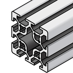
The 4040's I'm probably going to use for the center, will also be a different style from the ones I used before. Instead of having 2 rails, they'll just have 1, they look like this:
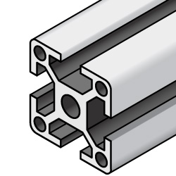
Instead of
These 4040's are a tad bit more expensive, but they're way more compatible with the 4080's than the 2 rail ones and are a bit more rigid.
Now I have to actually rebuild the frame in my design.
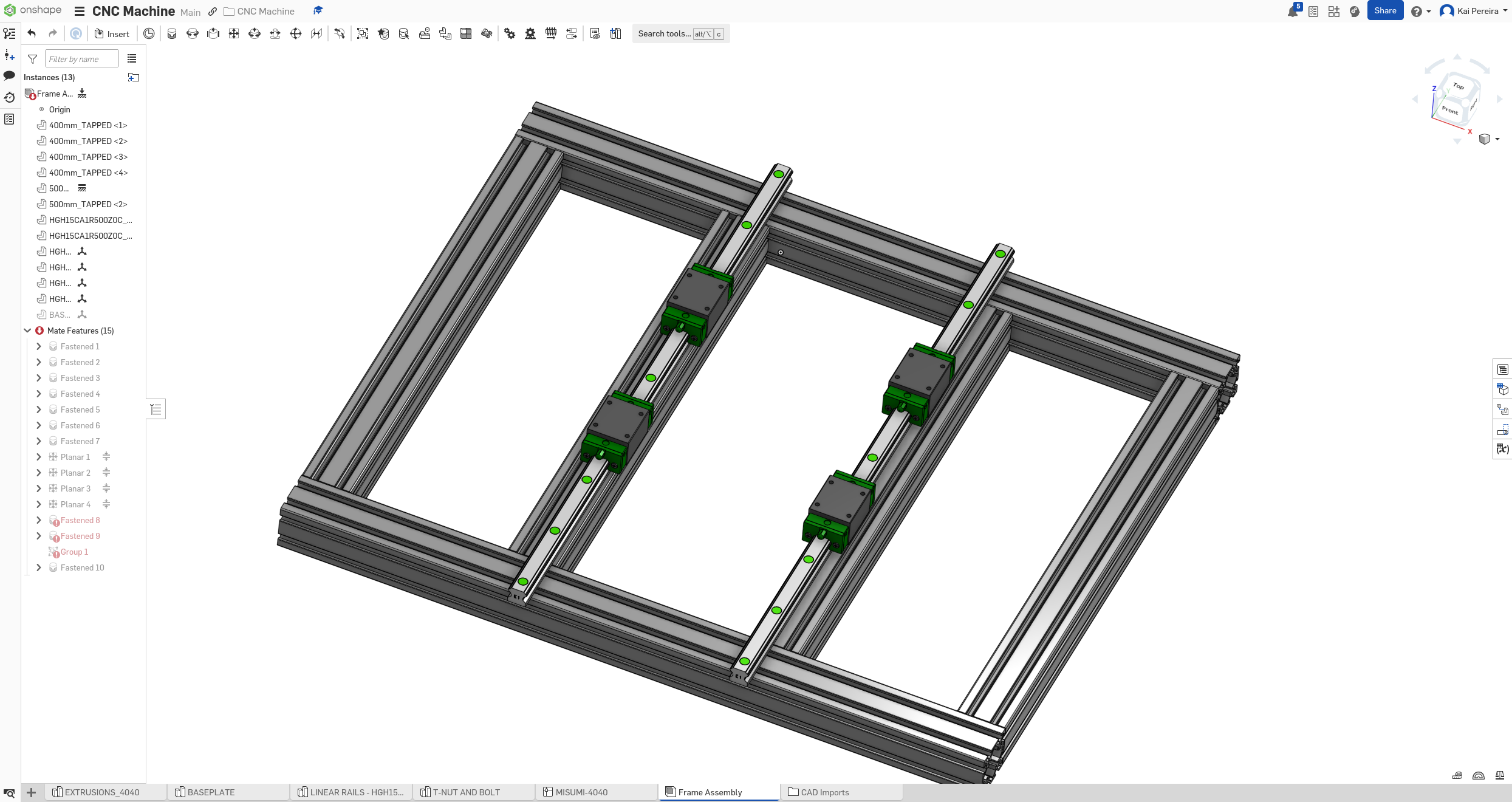
First off I got the basics of the frame down. The outside is 4080's and the 2 inner beams are 4040 (which I'll maybe turn into 4080's).
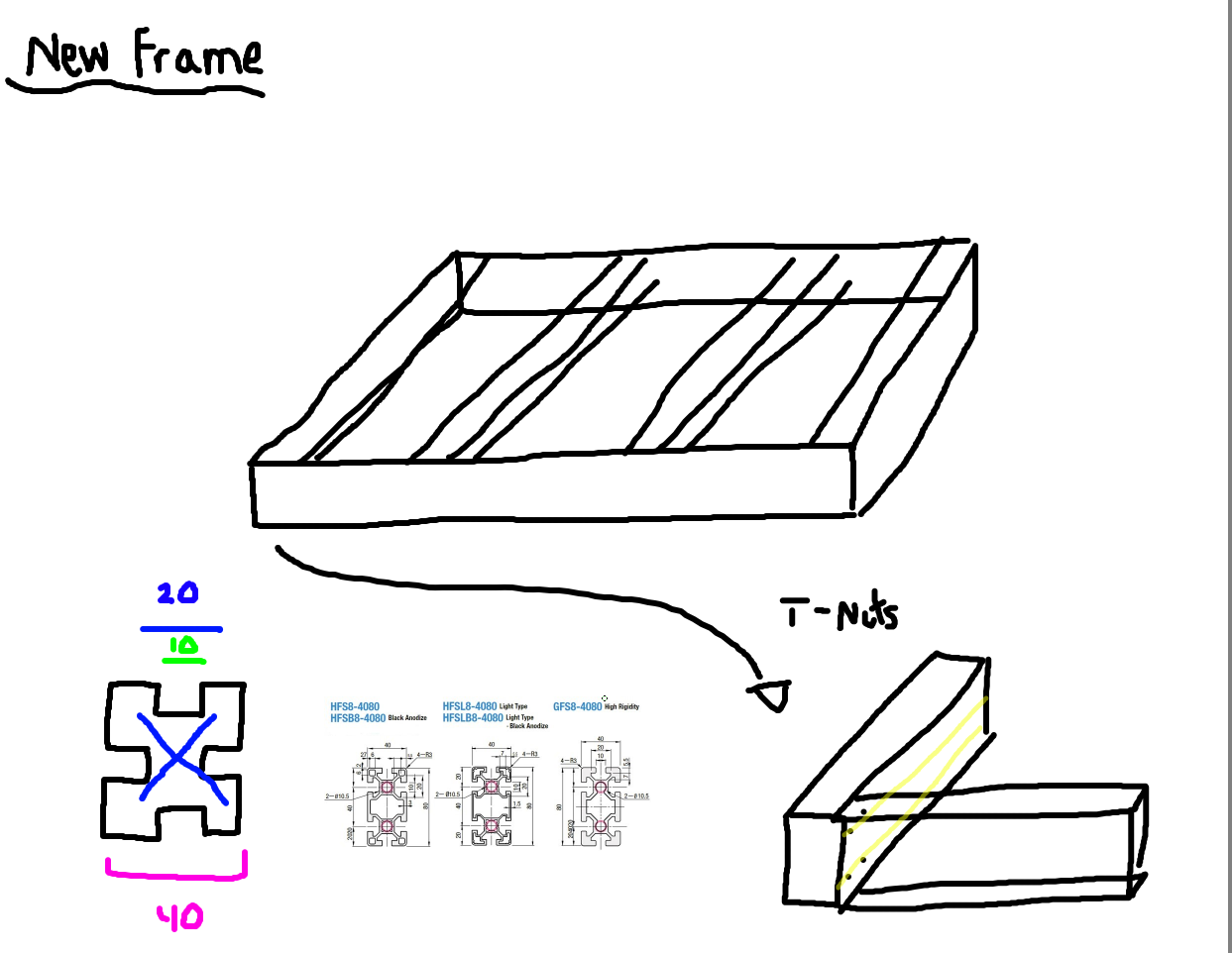
The beams are going to be attached by 4 T-Nuts on each beam and maybe some other supports on it too.
After a bit more research, using T-Nuts probably isn't feasible. Maybe using T-Nuts with something else could work, but probably not. I've been looking at a couple other options though: - Internal corner connectors (rigid and cheap, basic tools) - Diagonal bracing on some areas to make it stronger, like the side panels - Plate that attaches the corners - External connectors of some sorts - Maybe some T-Nut stuff, I'm not too sure
I'll have to look into this a bit more, but for now I wanted to fix my CAD drawing so that it included the 4080's and 4040's instead of the old 4040's with 2 rails.
It wasn't too complicated to change (though it probably took me too long because I kinda spent too long fixing really minor mistakes I was making), but I finally got it done, and it was looking RIGID. I feel like this is the perfect price/rigidity ratio, and I Feel like it will work perfectly, especially with the strong linear rails!
I'm planning on probably doing aluminum plate, maybe like 10 - 12mm thick, for the side panels, because they need to be one of the most rigid parts of the machine and I feel like plate is probably the cheapest way to get that.
I feel like my budget might be going a bit over, but luckily Hackclub is about to release their next event where I'll be able to get a $350 grant for my project, which will hopefully allow me to build this for little out of pocket! (I might even get to go to San Francisco too!). I'm estimating the project will probably come out to a bit over $400, more than the $300, but I like to set really hard goals and then fall short a bit, but still over-perform!
So for tomorrow, I really need to think about how I'm going to actually connect these extrusions and what I'm going to do for side panels. I haven't had much time in the past 3 days to work on this, so I'm glad I'm finally getting an update out. This update probably took me about 3 days, but I still got quite a bit done, and I can definitely feel like skills improving. I also still want to maybe reach out to some local companies about sponsoring, especially for the side panels, which would be a LIFESAVER!!
The CNC mill is coming along amazingly well, and it's really motivational to see a realistic frame come out, and I'm really excited to keep on working on this.
Total time: 36 hours
Day 1 - Fastening
I found this really cool build guide that shows all the steps in building an Avid CNC . It gives me a lot of cool ideas on fastening.
Personally I feel like I'm going to go with a mix of T-Nuts, internal connects and external brackets and now I'm also looking at anchor fasteners.
Anchor fasteners
I found this tutorial gives cool ways of attaching 4040 together. It's honestly pretty boring researching different ways of fastening stuff together, but now that I had a bit of an idea how to fasten stuff I wanted to do some side panel stuff and maybe work on the X axis a bit.
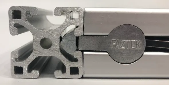
There weren't many resources on side panel dimensions so I kind of winged it, but I knew it had to be rigid, and that the Z height couldn't be too large or it would decrease rigidity and maybe move a bit. So I did a bit of calculations and decided I wanted a clearance of at least 10cm, so I kind of just arbitrarily set the Z height to be 250mm. This gave me 13cm of clearance and I think it's going to work. I feel like it's probably not hard to make it taller or shorter if I need, but this gives me a good amount of space while keeping rigidity in mind. I also just made the side panels 12mm thick, and 15mm wide, I'm honestly not too sure how big to make them, but it's easily changeable.
Next I wanted to work on something a bit new, the X axis. The X axis is going to be between the 2 side panels and needs to be long enough to clear the work area while maintaining rigidity. There's tons of different ways of attaching the X axis on: - Bolting extrusions to the side panels, and then mounting rails onto those - Bolting a beam or another extrusion to the top face of the side panels and then attaching the rails onto that. - Bolting an extrusion or another panel to the front or back face of the side panels - And there's probably a couple other ways but those are the main ones
I also recently found this site called open builds that literally just has like hundreds of hobby cnc mills, routers, lathes and so much more. This is going to be a massive spot for inspiration on design ideas and whatnot. Personally I feel like I probably want to just bolt some extrusion to the side panels and then mount the rails onto them.
I can either bolt 2 smaller 4040's or something to them, or one big extrusion panel to act as a face, and I feel like the price difference isn't actually huge so I'll just compare rigidity. I feel like maybe using some extrusions to support the beams in the dead-space beside the bed too would make it even more rigid.
Overall it was a really boring day of just researching and brainstorming. I know it probably looks like I didn't do much, but I'm spending a lot of time on the brainstorming so I can maximize the success of my project. I feel like people don't use enough thinking on their projects these days, but it's really what the key to a perfect product is.
It was also next to impossible to find resources on connecting 4080 for CNC mills, so I had to really dig to find information, they'res no good tutorial or overview on how to make a CNC mill so that's really what I'm trying to do. So now I have a really good idea on how to connect the extrusions, I also pretty much know how I'm going to do the side panels and also the beam between the side panels.
Tomorrow I really want to get the beams into the CAD design (along with the rails) or work on connections which I always like procrastinating.
If you got this far into the log so far, just remember:
Perfection in Details - Steve Jobs
Total time: 39 hours
Day 12 - Gantry and ballscrews
Alright so I've gotta work on the gantry bridge, that connects the 2 side panels, has 2 linear rails, and moves with a ball screw. This is a KEY part of the CNC mill, so it needs to be well made.
The 2 side panels are going to be 10 - 12mm thick aluminum plates (other dimensions are a bit unknown at this point) and now i just need the bridge. There's 3 main options I can go with for the bridge: - One wide piece of extrusion that will go from one to the other and will have both the rails on it (like 8080 or like 2080 I'm not too sure really) - 2 smaller pieces of extrusion like 4040 that will be separate bolted and separated, each carrying a linear rail, with the ball-screw probably in the center - 2 smaller extrusions like 4040, bolted together using joining plates and then fastened together to form a wide piece of extrusion that might be cheaper than just buying a wide extrusion.
I'm going to try using a piece of 8080 I think, because it's going to be really strong, and I don't think I'll have any problems with it! The problem is it's a bit expensive, but I think it is the most rigid option, and the easiest to just fasten on. Another problem I see with it though, is the rails are probably going to be pretty close to each other, but I could actually mount the linear rails to the top and bottom, which would probably be pretty effective, because it makes use of gravity to keep the rails on, making them more effective.
When I added the 8080 extrusion on though, I noticed that I didn't account for the lower clearance when there's something big up there, so I added 5cm to the side panel, to give 11cm of clearance on the Z.
Now the mill is looking pretty rigid, and I feel like this is the perfect size I need, and the panels just by change, makes it look like the spindle can be perfectly center on the work area with a bit of extra clearance for the rails and ballscrews:
Now I wanted to put the rails onto the gantry bridge just to see how much space I'm working with here, and because that was my original idea for mounting the rails onto it.
But when I added them in, I noticed that it doesn't seem like there's enough space for the Z axis mounting plate to be put on, and I feel like this is probably a rigidity issue.
I've decided at this point that's it's probably a good idea to get my ball-screws into the design, because it's actually going to impact a lot of my decision making. I know I can't fit the ball-screw in between the rails here, like I'm planning on doing with the bed, so I need to come up with a different way of putting the ball-screws or rails on. My 3 ideas are: - Mounting the rails on the top and bottom of the extrusion and then passing the ball-screw though the center, I'm worried about concerns of efficiency though when gravity starts pulling the z axis down onto the bottom rail - Making a larger extrusion and then mounting the rails onto that with the ball-screw in the center - Leaving the rails like this, but putting the ball-screw on the top - this feels a bit sketchy though so I don't really want to do this.
But now I kind of have to put this on the back burner and work on choosing my ball-screws and getting them into my design.
There's TONS of different types of ball-screws and screws alike, which all have their advantages and disadvantages, the problem is really choosing the ones I need for my CNC mill. The main criteria I have are rigid and decently cheap.
Here's the main types of screws I could use (if you want to take a look at the technical specs, this document is pretty good): - Rolled ball screws - budget and good rigidity - Ground ball screws - higher precision and more expensive - Ball re-circulation style ball screws - Some wacky expensive thing I don't know (I'm not worrying about these honestly)
and then there's grades for all these too, ranging from C0 (most precise) to C10 (least precise). C7 is kind of the mininum accuracy you want for a CNC Mill and everything above that works.
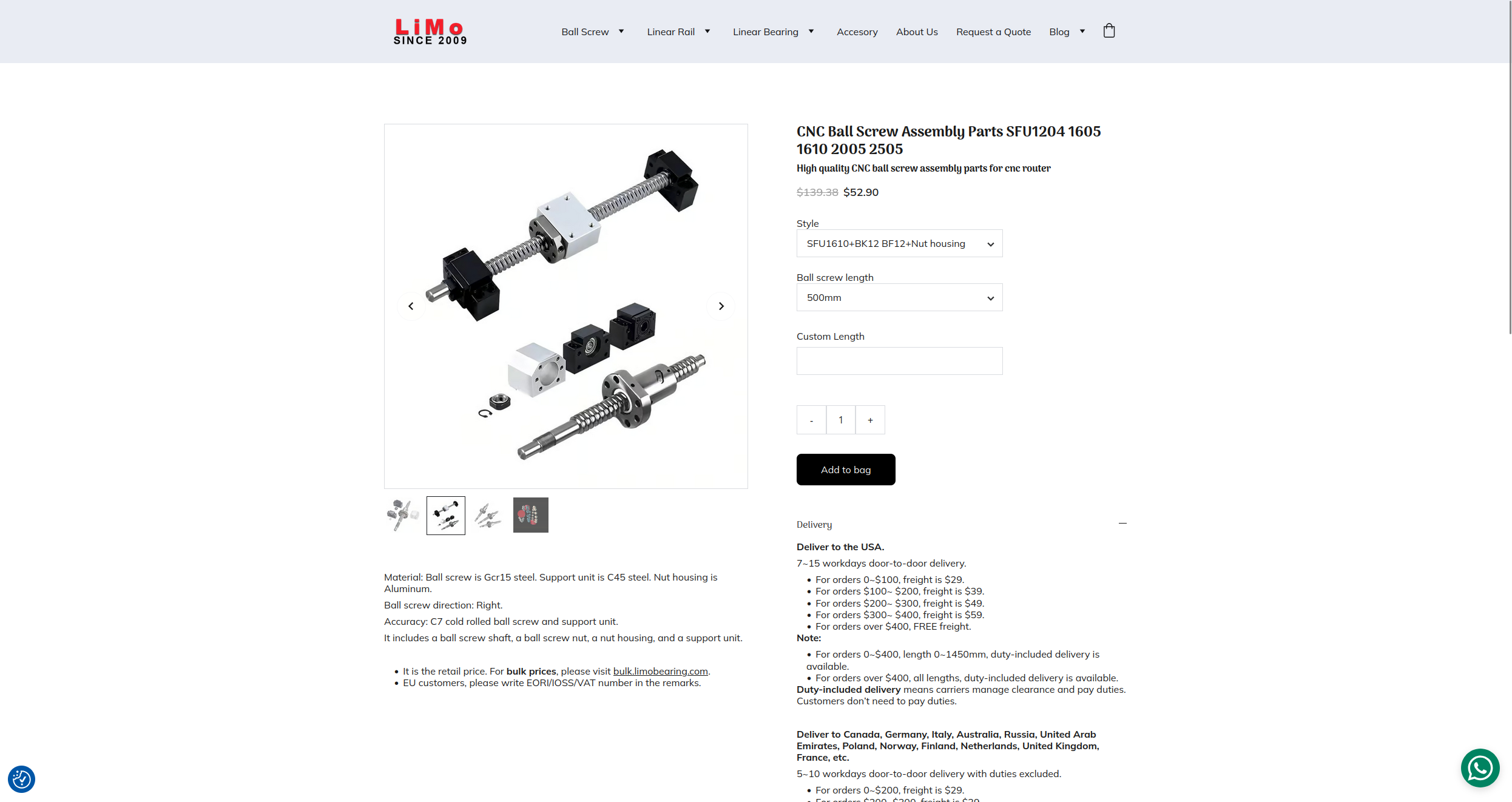
AND THEN, there's a bunch of identifying measurements for all of them. Let's take the SFU1605-600mm for example: - S - Shaft - F - Flange Nut - U - Preloaded single nut - 16 - 16mm screw diameter - 05 - 5mm lead - 600mm - overall length
So there's a lot that goes into choosing the ball-screw.
After doing a bit of research, and looking at the PrintNC BOM (for all you newbies out there, a BOM is a Bill of Materials, it's basically a list of all the machine parts), I found out that I can use 2 different types of ball-screws for different parts of the machine.
- The Z axis is going to have to work against gravity, so it needs to have more lifting power and less speed, this means I can go with a thinner ball-screw like an SFU1204.
- While the X and Y axis need more speed because they cover lots of distance, and less mechanical advantage and are also not fighting against gravity like the Z axis, this means we can use a thicker ball screw like the SFU1610 for the X and Y axis.
The SFU1610 is a bit more expensive though, but the price difference is only $10 so because I'm using only 2, I think it's a good trade-off to make.
Now I've decided what ball-screws I'm going to use, all I have to do is get them into the CAD design and then workout some spacing. I have a feeling, I might need to make the space between the extrusions below the bed a bit larger so that the ball screw can fit in and be nice and rigid, but we'll see when I'm designing this stuff.
I feel like I got quite a bit of stuff done today and tomorrow I'll probably work on the CAD and then probably work out the new headaches that arise from adding them in.
Total time: 41 hours
Day 13 - Everything Ball-Screw
Ball-screws are so complicated and I just keep on learning more and more about them. First of all, there's different types of ball NUTS: - Single nut - Compact not much backlash - Double nut - Precise - Flange type - Easiest to mount
Also a term I've been learning is backlash which is essentially if a part is loose or not and will degrade accuracy of your parts. It's important that ALL parts have minimal backlash to ensure a rigid machine that cuts nicely. That's why I've found it important to use high quality parts!
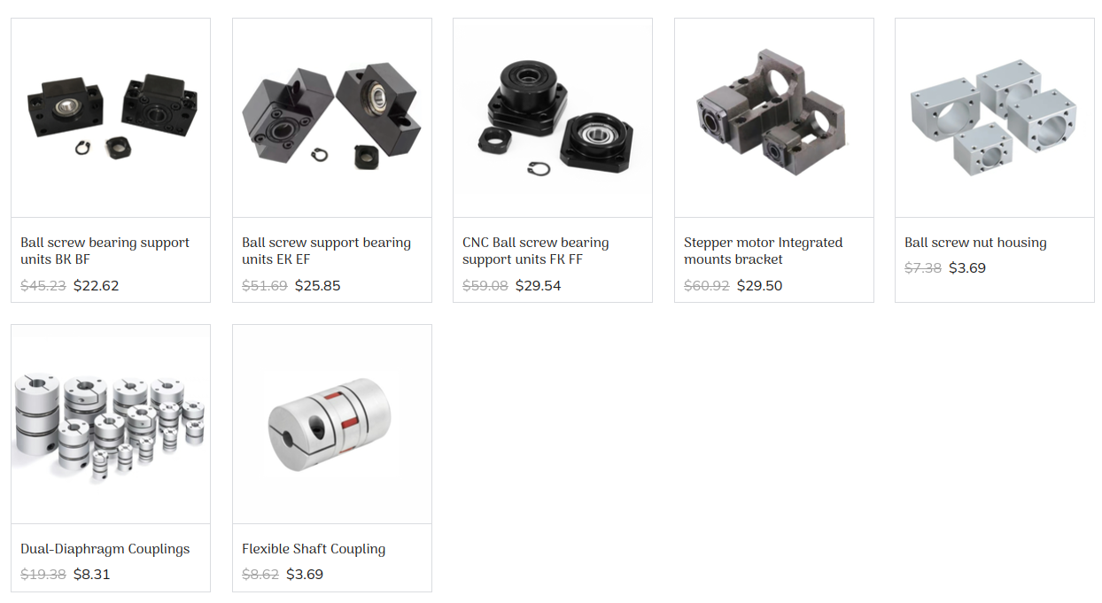
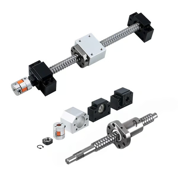
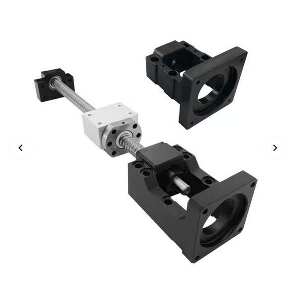
And then you actually need a couple things to go with your ball-screws. These are the end supports, couplings, ball nut housing, thrust bearings and a motor mount. Pretty much all of these I didn't realize you needed so hopefully they're cheap :)
Here's a bit of an overview of each: - End supports support the ball-screw on both sides, they come in 2 types: - Fixed support - Uses a radial ball bearing which supports the radial loads - Floating support - Uses an angular contact thrust bearing which takes axial/radial forces off the screw (I'll digest these down soon, but if you want to learn more, check out Kiwi Motion) - Couplings connect the stepper motors to the ball-screw shaft - The motor mount holds the motor in alignment with the screw - The thrust bearings are inside of the end supports and lets the screws rotate
All of these are next to essential (I think there's some cases where you don't need all) so I definitely need to include them, I'm just not quite sure which ones.
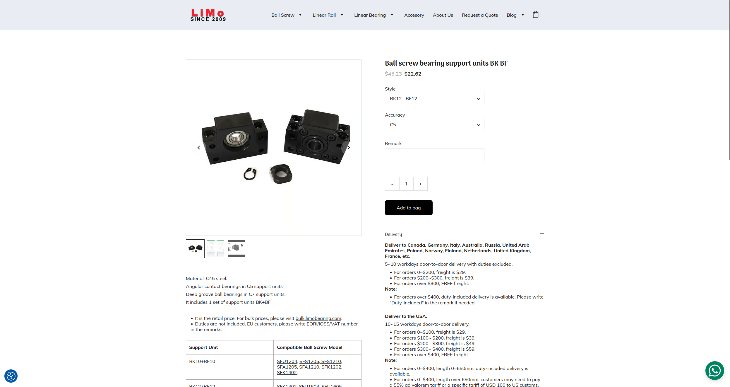
After doing a bit of research, I've found out that a combination of floating and fixed end supports are the only really viable option. Now I thought that these supports would maybe just cost like $4 a pop or something, but NOPE, they're like $22 for each set.
I'm definitely considering finding a better supplier of them, but I actually might be eligible for the free freight if I include these too, maybe I could also get free freight + a coupon code.
I also really want to send maybe a sponsorship email to LIMO bearings because they all-around have the best prices of the any place I've looked at so far. So that's definitely something on my TODO, although, they are chinese so it might be a bit harder!
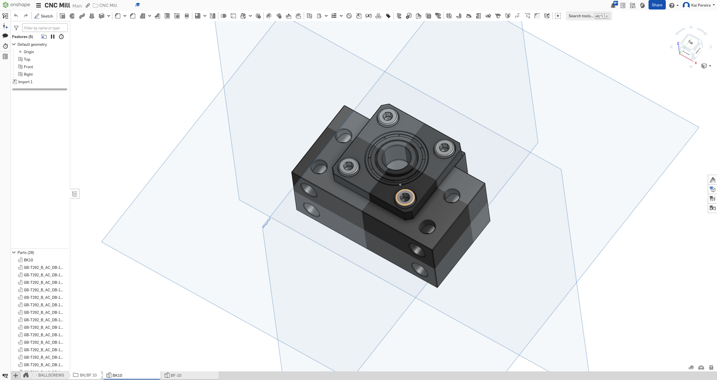
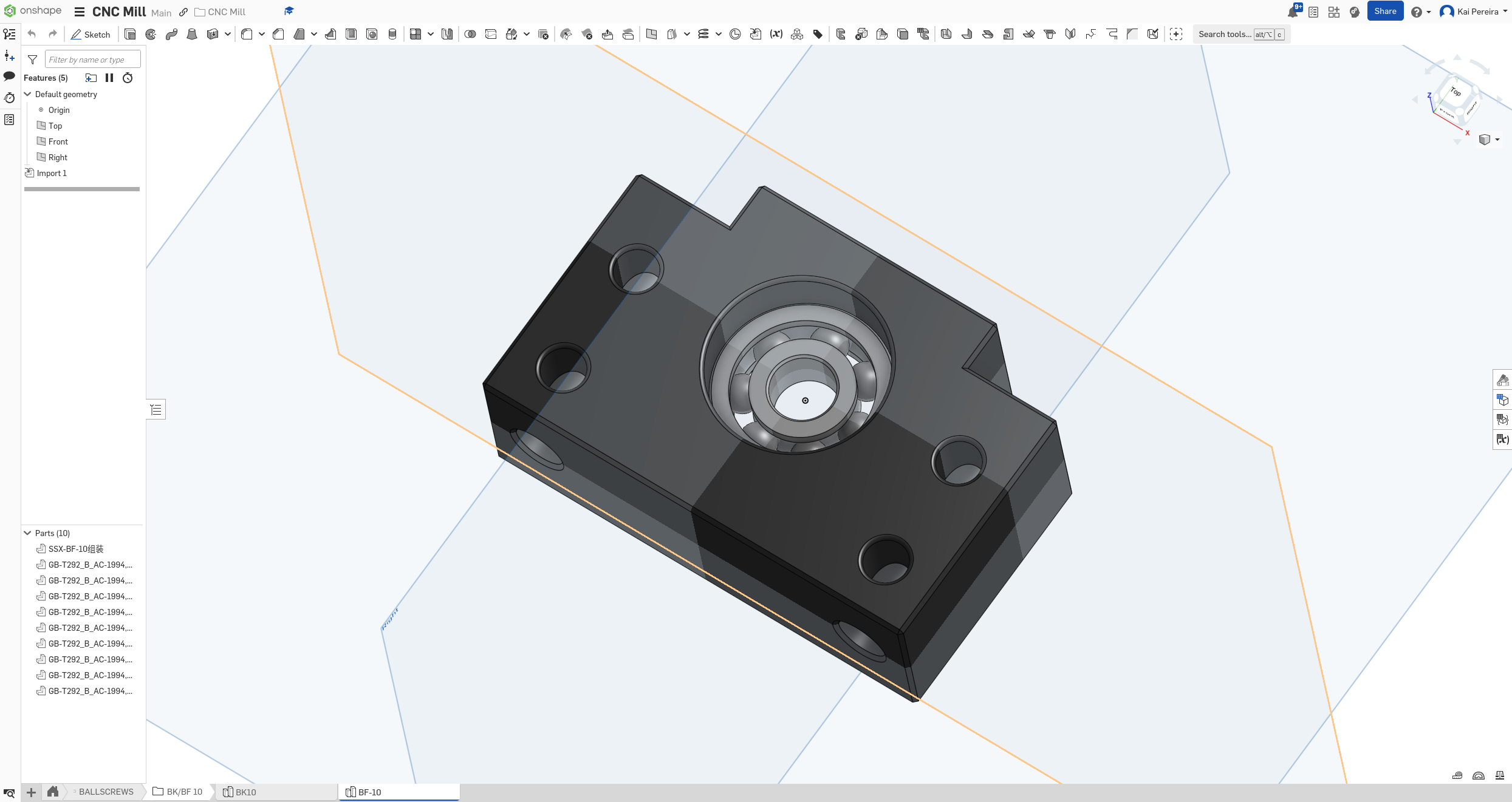
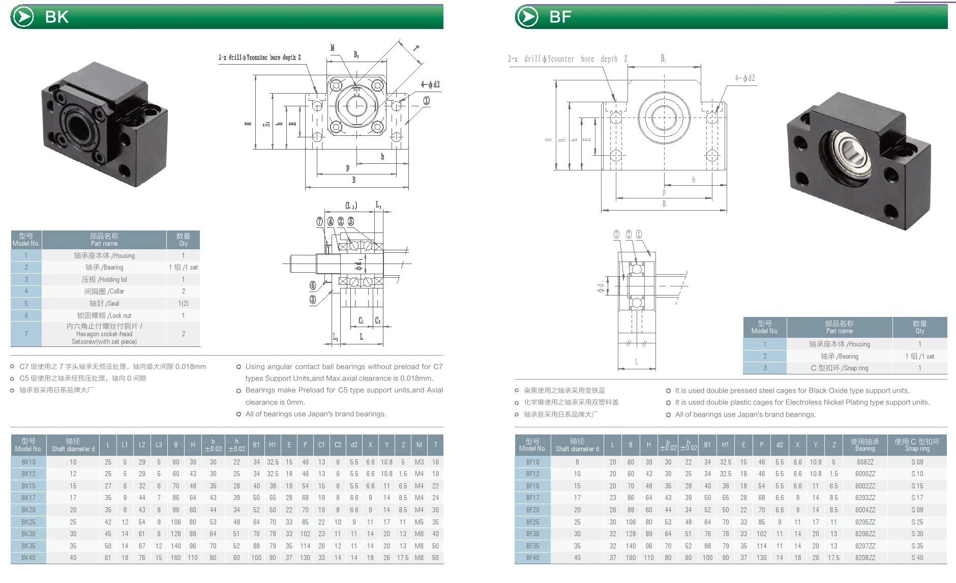
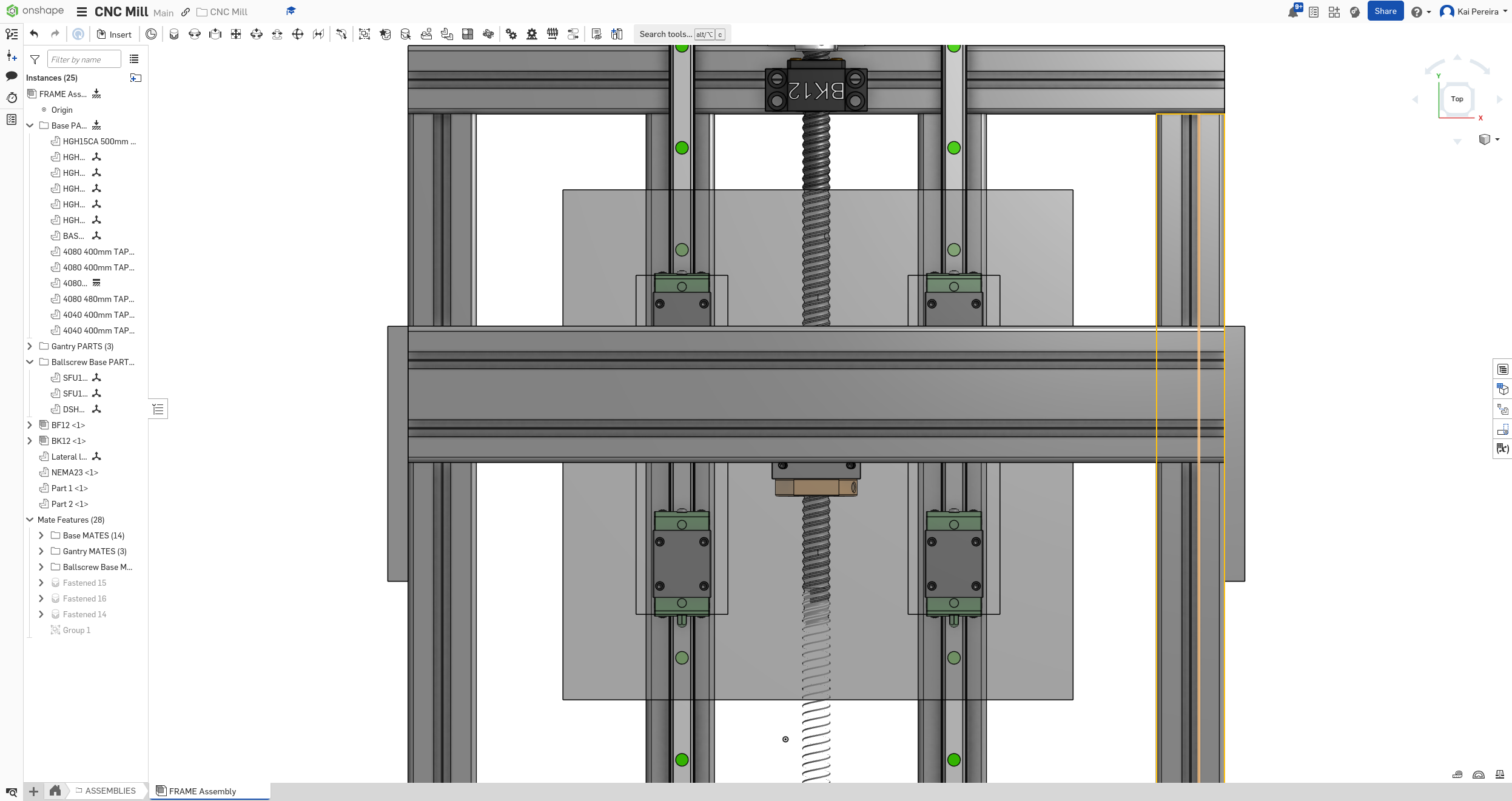
But anyways, I'm not quite sure what the naming conventions for these are, but I know that the 1610 ball-screws need BK12/BF12 supports and the supports for the 1204 ball-screw is the BK10/BF10!
It really annoys me that these are so expensive, and it just makes me think, that if I had all the parts to mill these myself and other parts, how much money I would probably save (though with a lot of pain). I think I'm a bit off track with pricing though, and I feel like I'm aiming for about $500 now. But I'm still really happy I get a $350 grant from HackClub because that will carry the project so hard. (if you're a high-school/middle school student, JOIN HACKCLUB)
From looking at the LIMO bearings site a bit more, I've found that they actually have all the parts I need for the ball screws, but they're SOOO EXPENSIVE, which is definitely making me wanna find a different supplier for my ball-screws.
It would cost me nearly $75 per ball-screws, which is a bit too much, I'd prefer if all the ball-screw came out to $150, which I think should be definitely possible. It's just really annoying the LIMO doesn't have like a set that's maybe cheaper than all of these separate parts combined!
After doing a bit more research, with a lot of deep diving, I think I could find some good stuff on aliexpress for a bit cheaper, but with the no shipping fee's on my order, it might be a better idea to get from LIMO. All the parts from LIMO come out to around $320, which I feel like is a bit too expensive.
I also need stepper motor mounts, but I feel like I'll be able to get these for free or so (somehow, someway I don't really know) so I'm not going to include these quite yet.
Now let's price in extrusions and mounts, and BOOM, we're at like $600. So I feel like the ball-screws and the rails are the 2 things I need to bring down in cost.
BUT GOOD NEWS! Undercity just dropped while I was working on this so now I'll get a $350 grant from this!!!!
Now I need to kind of figure out what size shaft couplings to get. Shaft couplings come in all shapes, sizes and types. Here's a quick overview of the 2 main types I really care about: - Rigid couplings - can't really tolerate any misalignment's - Flexible couplings - Can accommodate small inconsistencies/misalignment's and absorbs shocks and vibrations better
This is a flexible coupling by the way:
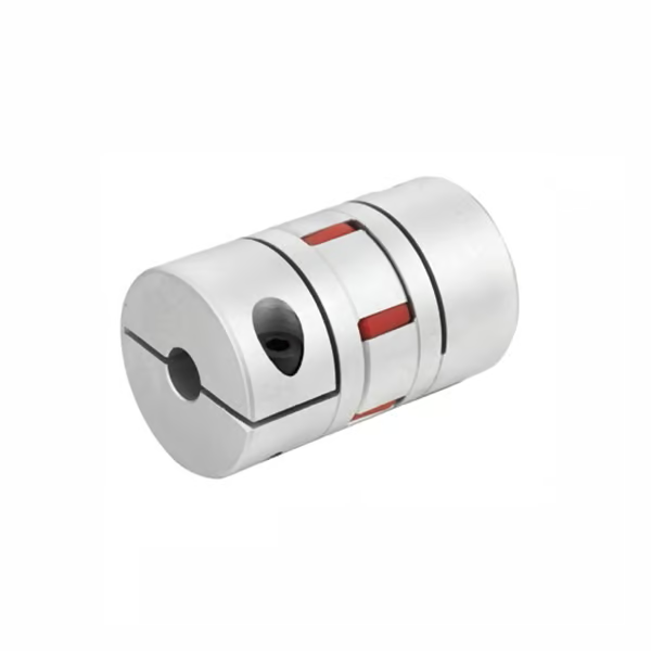
And then there's lots of different sizes and a couple more types which I'm not going to go into detail about because they're all very complicated to describe, just check out Linquip. I'm going to go with flexible/jaw style couplings because there's going to be lots of action and a bit of tolerance on my mill and they'll help absorb some vibrations.
But the sizing is really weird on couplings so I gotta figure that out now. I know that my stepper motors have a shaft diameter of 8mm and that my ball-screws have a shaft diameter of 10mm, so I need a flexible coupling that accommodates for that.
I honestly might just order the flexible couplings from amazon because I have like $150 in amazon credits I really need to spend, and it's hard to tell from LIMO whether their 10mm flexible coupling will work.
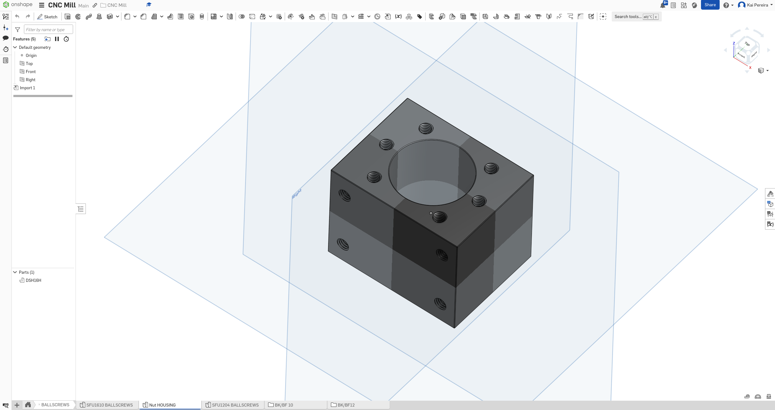
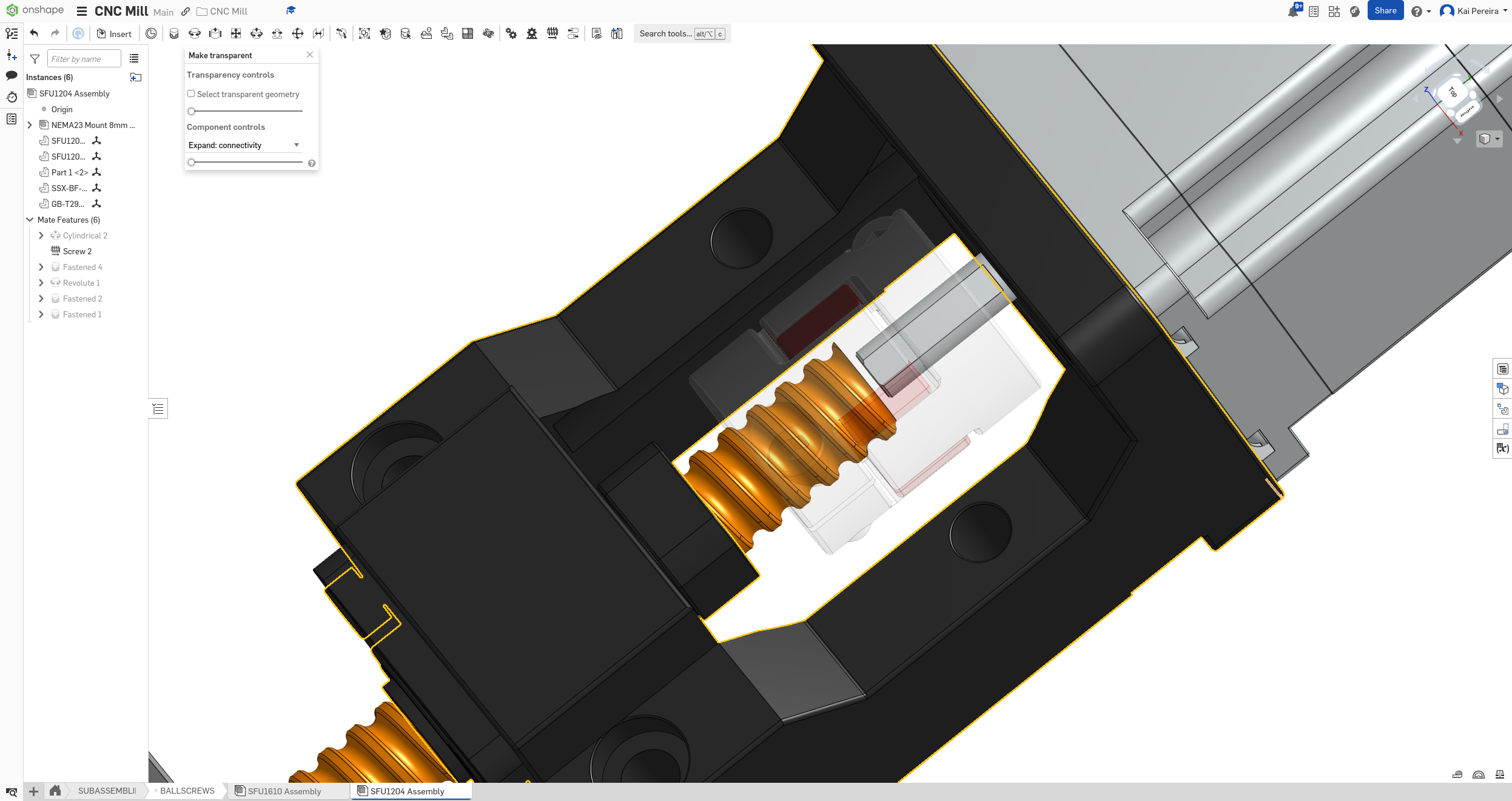
Now I need to figure out what screw nut housing to use. Base off the LIMO bearing sizing chart, I think I can just go with the ID 28mm. There's also steel and aluminum ones, personally I'm just going to get the aluminum ones because while they're less rigid, my whole mill is made out of aluminum so it should balance nicely, and it saves me like $30 and it's easy to switch them out if I make a mistake!
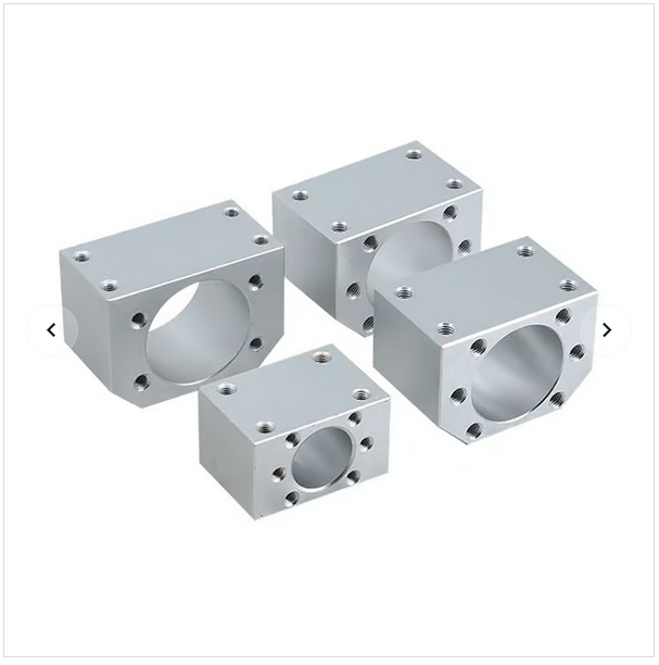
Some screw nut housings
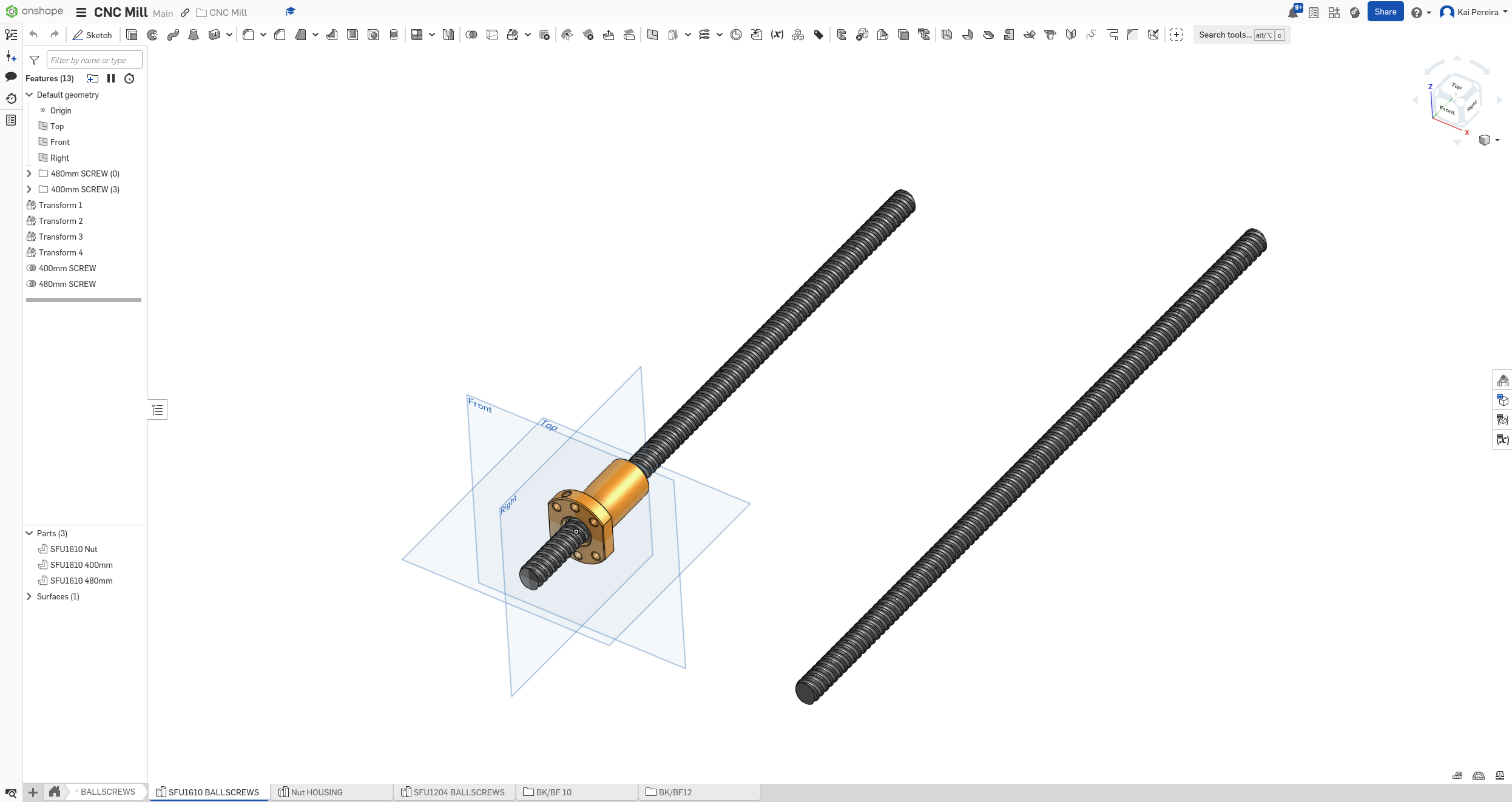
But anyways, I know exactly what type of ball-screws I want, so time to model them in! These are all the parts of them: - SFU1610 or SFU1204 Grade C7 minimum - BK/BF 12 or 10 support units - Flexible Shaft Coupling - Aluminum DSG1610 housings - Stepper motor bracket mount - I'll think about this more because I'm not too sure about these yet
AND WOW, THAT'S A LOT OF INFORMATION, for me too guys, don't worry 😭 . And just like that the day went by without me even working on the CAD.
I pretty much have the ball screws dialed down, it would be nice to bring down the costs of the ball bearings but I can actually CAD them now. I got a LOT of stuff done today, and I'm so glad that the majority of the ball screw stuff is finished now, so I can focus on the actual important stuff.
I kinda LOCKED IN today
Total time: 45 hours
Day 14 - Let's CAD ball screws!
First of all I grabbed the CAD files for the ball screw off of LIMO bearings and then imported them into Onshape pretty easily. But the thing is, they give you the whole model, not the drawing or anything, so I'm having trouble making them bigger.
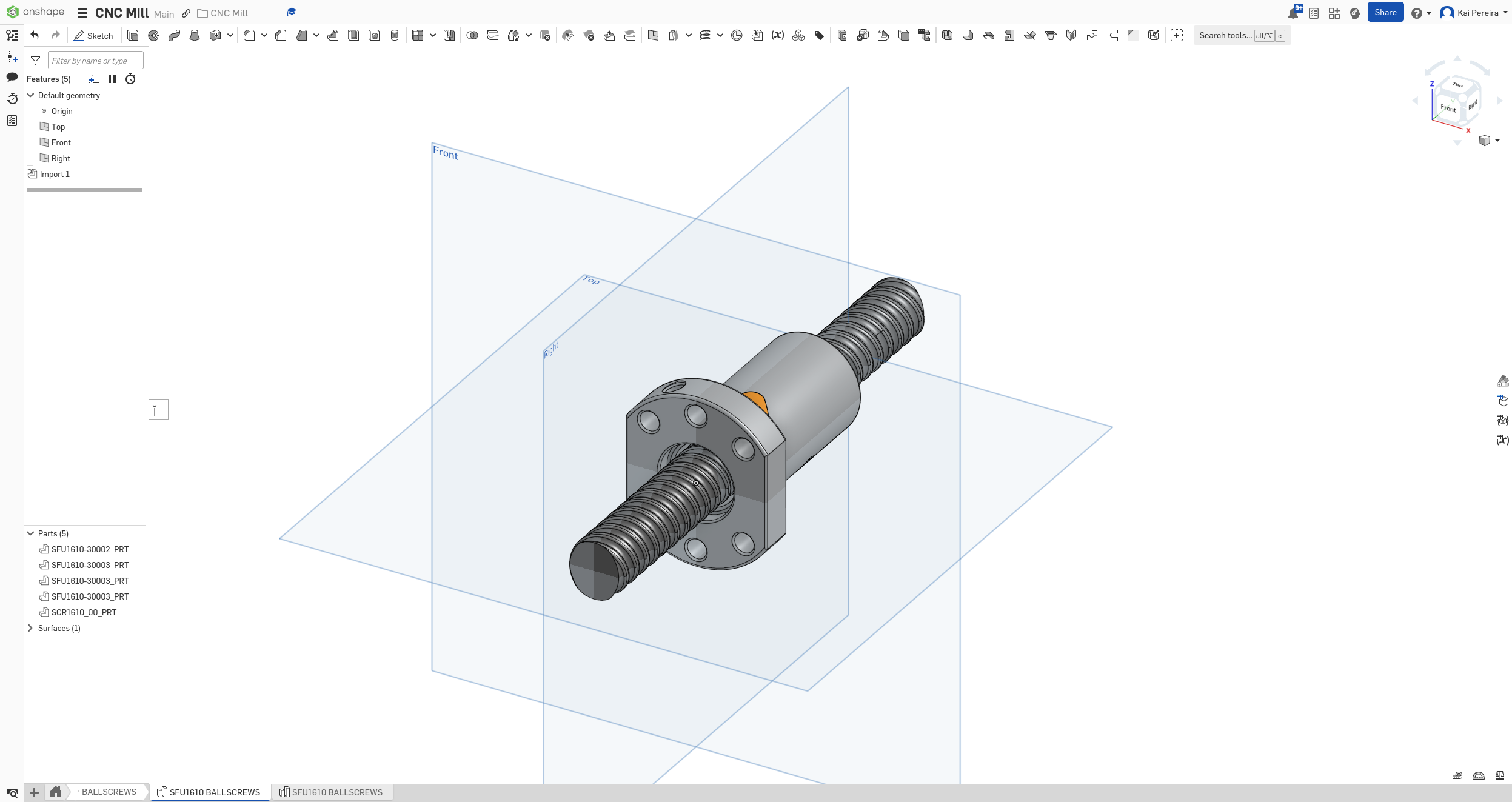
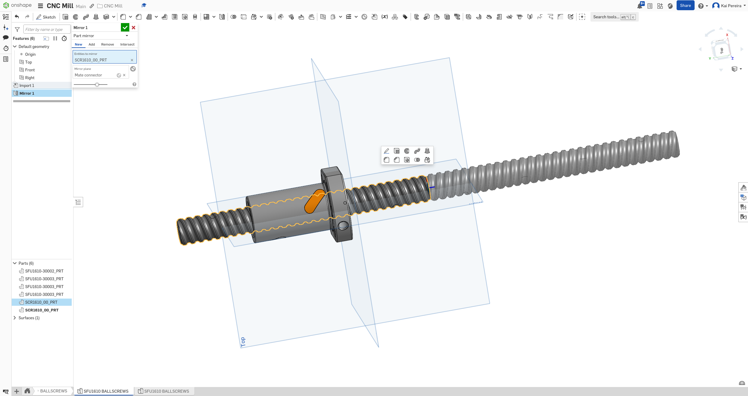
Using the mirror tool I can kind of get someone that looks nice at first glance, but I can't really do specific sizes. Time to consult the internet :(
Using transform actually gives me pretty nice results, I can line up the bearings and can pretty much control the size with some annoying math (but there's probably another way honestly). If I don't find a better way, this kind of works!
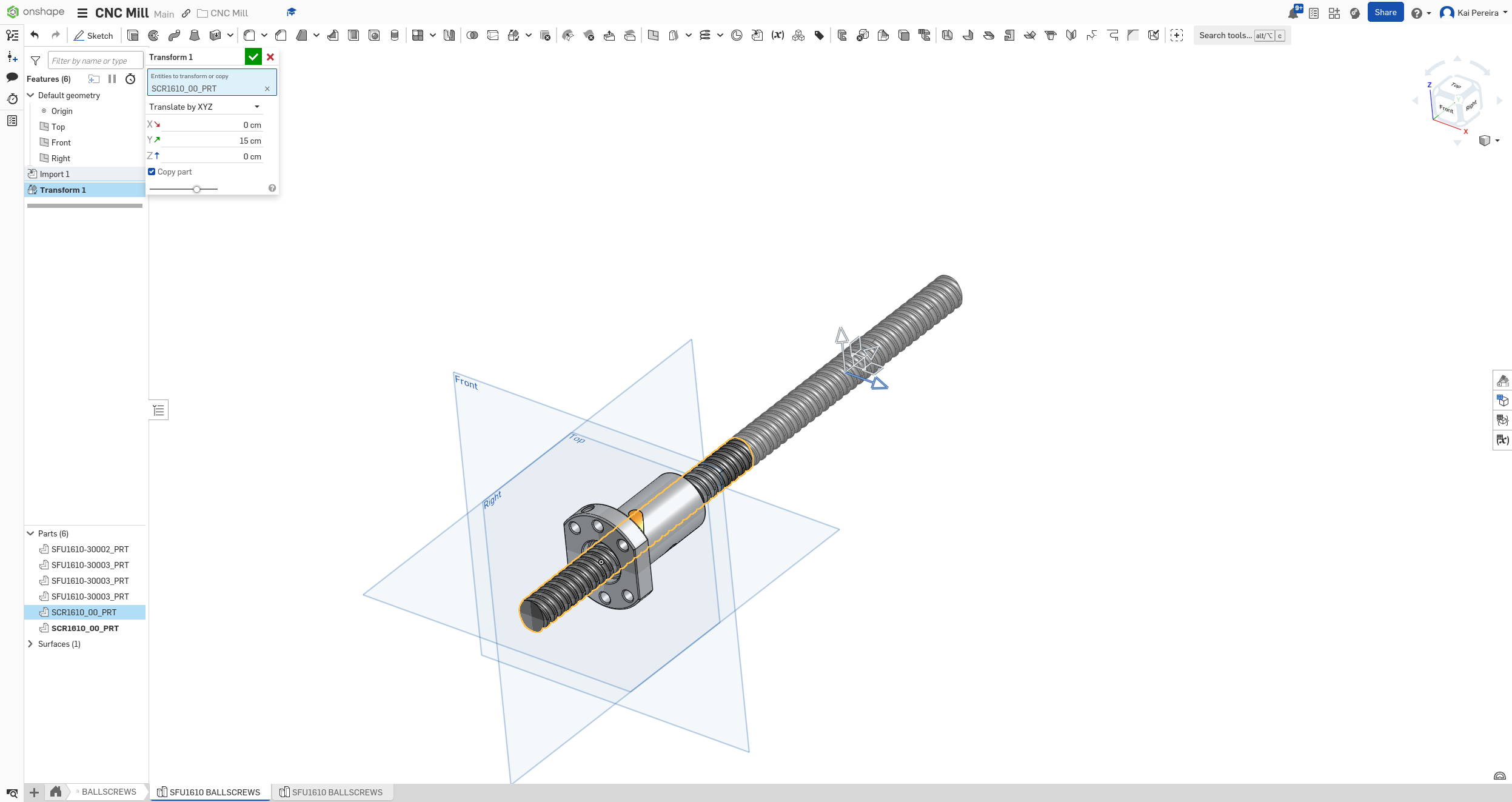
Now using some janky transformations, I have the different length ballscrews I need. I haven't quite started on the Z axis, but I know I need a 400mm ballscrew and a 500mm ballscrew (not exactly those but close enough until I make edits).
I used a boolean to turn all the separate components into one, which I didn't even know existed, but it works great!
Now I just repeated this for all the components I needed: - SFU1204 Screws - BF/BK supports - Aluminum housings (I used the steel model though because I think they're the same, maybe double check this though) - Motors
The hardest part to model way the stepper motors, because I got them from Facebook marketplace, they weren't like too common so it was pretty hard to find the model. I knew the exact model though, so I had the dimensions of them (using a page from walmart). - 55mm long - 8mm shaft diameter - About 65mm wide - About a 20mm long shaft
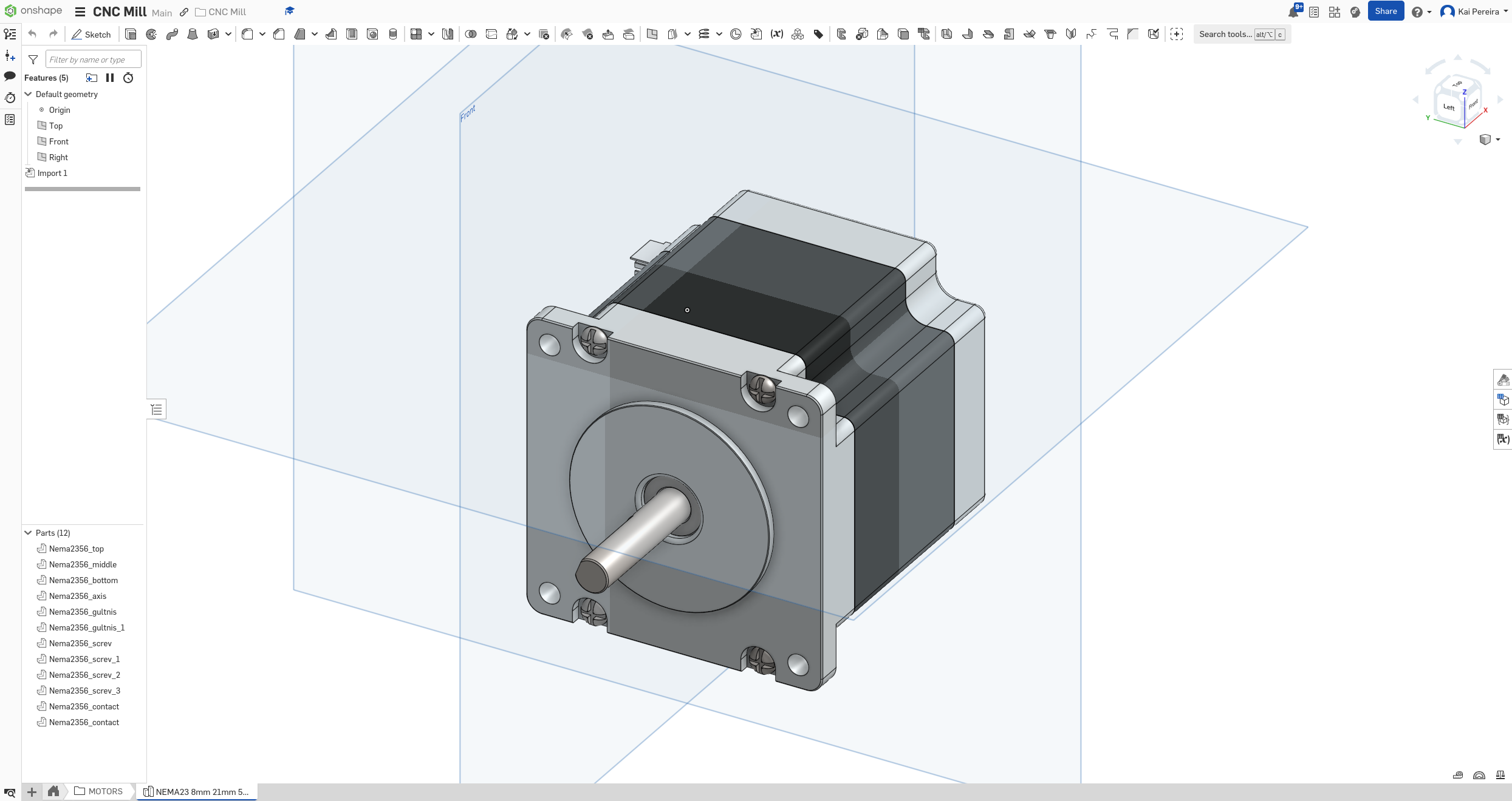
So I searched up NEMA 23 models
and then looked on grabcad for one with similar specs (because I couldn't find an exact model for this motor) and I came across this one. It had nearly the exact specs except the shaft diameter which is 8mm on my motors, but I'm not too sure if this matters because the design doesn't need to be exact, just the parts (I feel like I'm going to regret this later).
Looks pretty accurate
Not too sure if this is the exact specs of the aluminum one (this is the steel one)
Looks good
Couplings look good
I kinda procrastinated doing all this because doing so much work on one project tends to burn me out pretty fast so I just did 2 hours over 2 days for this stuff. But it's looking good and I'm excited to actually put it into the assembly. The ball screws are giving quite a bit of lag so hopefully that doesn't impact the assembly too much!
I also haven't done to coupling yet because it's like a weirdly specific coupling I need and I couldn't find a model for it. But anyways, I'll see ya tomorrow because it's midnight :)
Total time: 47 hours
Day 15 - More ball screw shenanigans
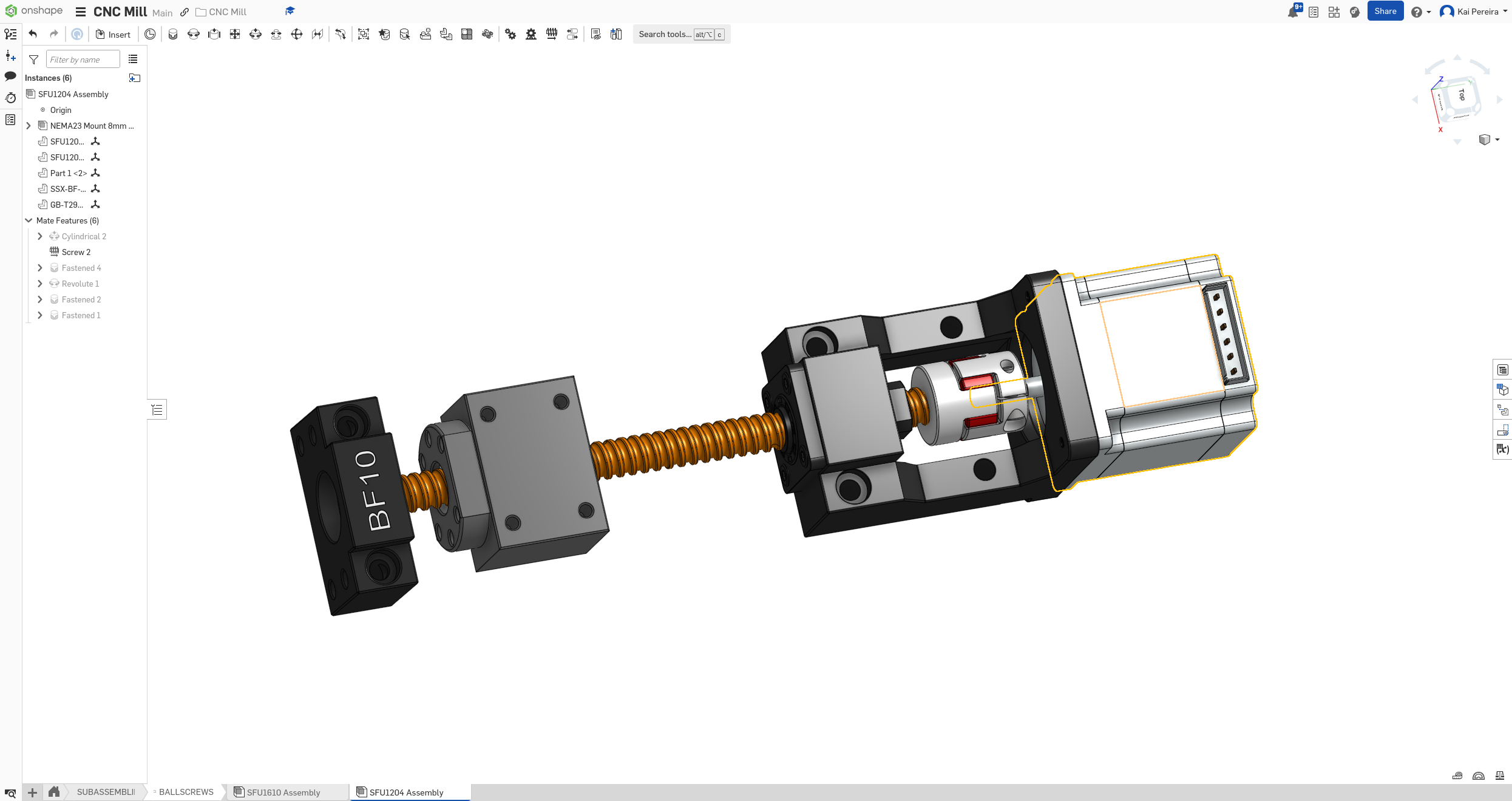
Now that I had everything except for the couplings modeled, I wanted to assemble some of it in my CAD workspace.
Things were getting a bit messy in the document though as I had so many part studios and multiple assemblies that I created some separate folders just to organize things a bit.
The main thing I wanted to assemble was the ball screw sub-assembly which was: - One ball screw - A BK and a BF support on each side (the fixed support was on the same side as the coupling) - The ball screw nut - Stepper motor - Shaft coupling - Motor mount
I had everything in the design except for the shaft coupling because it was still a bit perplexing to me.
Remember how I was talking about how the stepper motor mount brackets were really expensive and that I couldn't add them in because of their price. I just figured out that they actually have angular bearings in them which are the same ones as the BK support, so I can actually replace the BK support with the motor mounting bracket! This is absolutely amazing because it simplifies the building and only costs me an extra $15.
 Im dumb
So now I just had to find the right mount and then just put the STEP file into onshape!
I thought that maybe the stepper motor bracket would work, but after putting it into the CAD, I figured out that there was no proper size for it :/
Motor mount too small
I was still a bit burned out today so I didn't really want to deal with it for now. But I think maybe just a mount with the floating support would be the best and probably cheapest option and would still be pretty simple.
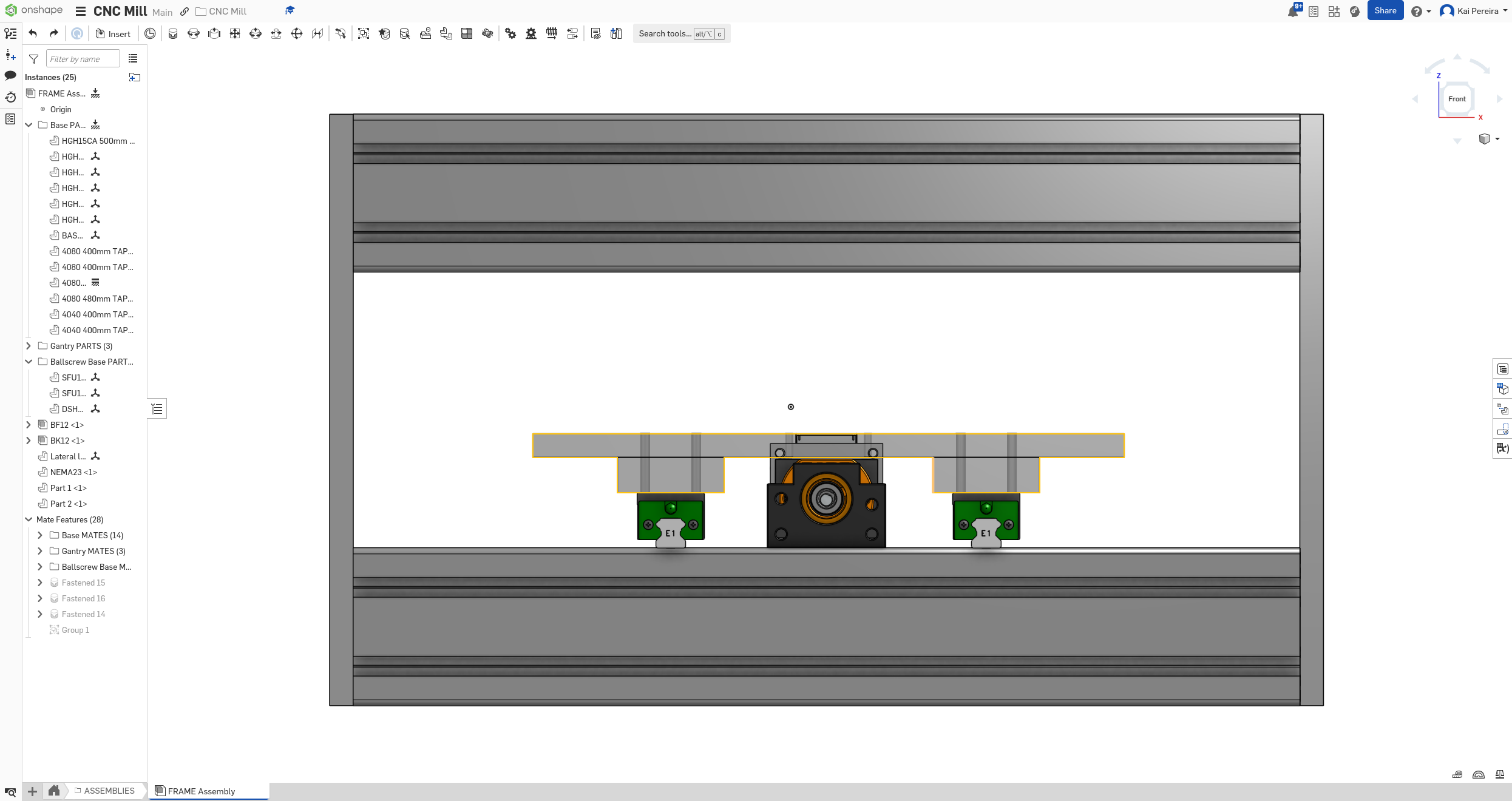
Now I just wanted to assemble the stuff I had already gotten together so I could start visualizing the ball-screw assembly a little bit more easily. Here's a brief overview of how the assembly will work: - The base screw and the bearing is the key things that are moving, the other components are static/rigid - The BK/BF supports are stuck to the frame and don’t move, the rotation from the screw into the stepper is transferred through the support bearing - This part confuses me a bit but the screw nut/housing is stuck down to the screw and stays upright, it’s a bit confusing to me because the nut isn’t actually rotating so I need to kind of figure this out in my head. - The motor coupling and stepper motor are moving with the bearing, the coupling is transferring the torque from the stepper to the ball screw
After a bit of thinking I think I’ve figured out the ball screw not moving the nut. The rail carriages that are fixed to the frame stop the nut from moving and instead just allowed the screws, bearing, coupling and motor to rotate (I hope this makes sense to people reading).
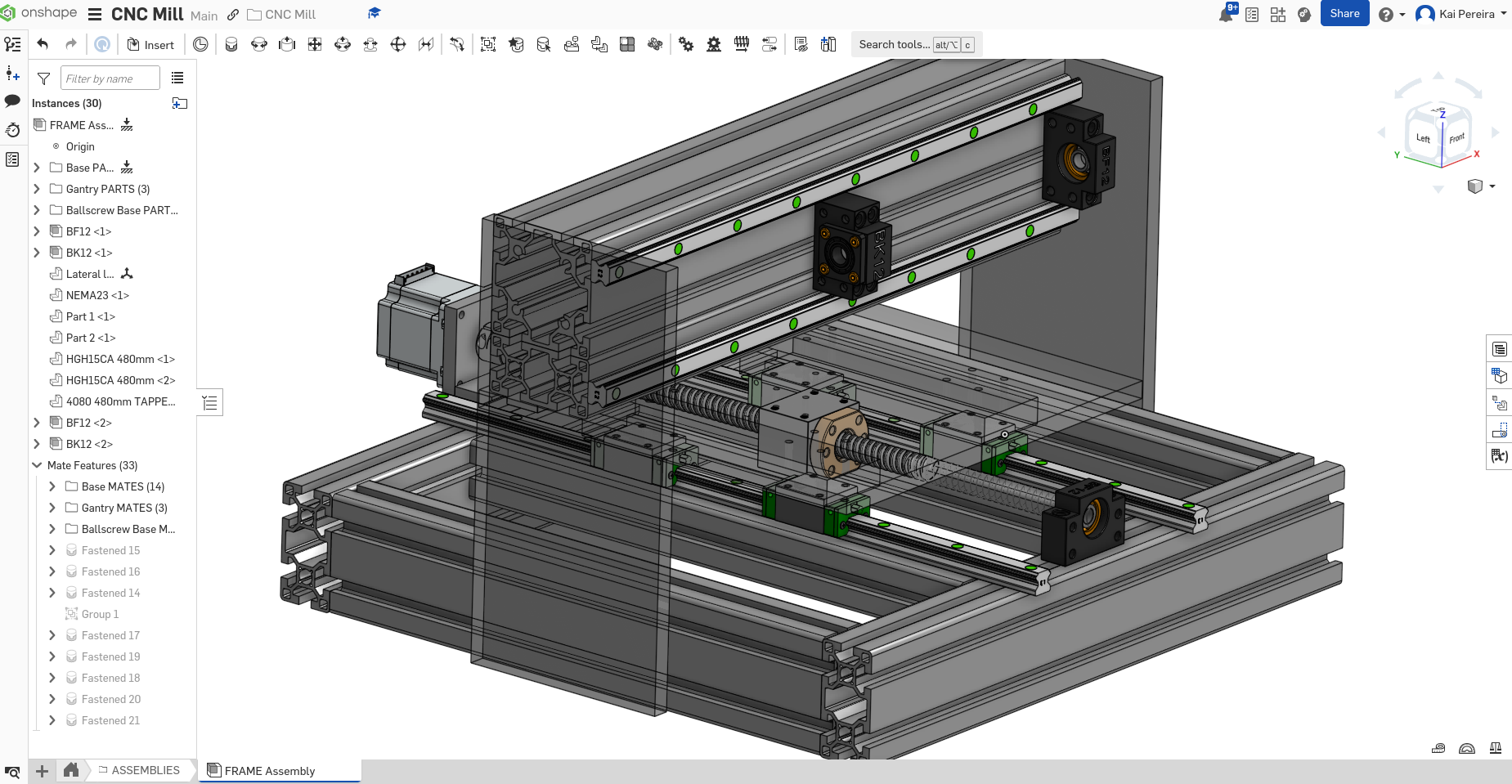
So after implementing most of this stuff in, I got this really satisfying screw assembly :D
I wasn't too productive today but still spent some solid amount of time, hopefully I'll really be able to do some grinding tomorrow because it's a 4 day weekend! But anyways, for tomorrow, I want to figure out what shaft coupling and motor mount to use, and then maybe model them in!
Total time: 49 hours
Day 16 - Stupid mistakes
After day 15 I realized that I had to use a separate motor mount because the stepper motor couldn't fit inside of the mount. Well that was just insanely stupid, turns out the stepper motor sites outside of the motor mount not in :D, definitely should've looked into that!
So turns out, I actually can use those motor mounts and they'll save me probably lots of pain.
Some days
Well now that that's out of the way, I just have to find a good flexible shaft coupling to use. I need one that goes from 8mm to 10mm!
I'm already ordering my extrusions from Misumi and Misumi also just happens to have tons of different types of couplings so I think I'll probably get from there.
After doing a run through Misumi it's WAY too expensive, just because of how they do their parts, I am definitely not getting my couplings from them. It was nearly $30 per coupling which is way out of budget.
I know that the SFU1204 to NEMA 23 coupling can just be a basic 8mm to 8mm flexible shaft coupling but the other one needs to just be 10mm to 8mm. So I kind of ignored finding the 8 to 10mm again and just worked on the assembly a bit more. I realized that my ball screw assembly was a bit off so I fixed that real quick (it was just some stuff was spinning that shouldn't been spinning).
I also decided to split everything into sub assemblies just to make stuff simpler and faster. I really like it this way because then I can have my BIG assembly and then medium sized assemblies that I can just easily add on and modify, it makes everything very straightforward so would suggest!
Now my ball screws models didn't have these smaller ends where the bearing and stuff slide into, so I'm not too sure where to put the supports and couplings, so I kind of just arbitrarily put the middle of the coupling to the ball screw end because I think this is how it is in real life. BUT I NEED TO DOUBLE CHECK THIS.
But while doing this assembly, I realized that the end of the NEMA motor travels pretty far into the coupling, so I might need a bigger coupling, smaller NEMA 23 model or it's just fine? I don't really remember how long the shaft of the NEMA 23's so I'm going to double check those now.
Anyways I'm ending today a bit short because I have to wake up a bit earlier tomorrow, but today I did lots of assembly stuff but the majority of the stuff was still spent on researching.
The main things I want to do tomorrow are: - research how the 2 shafts should sit inside of the flexible coupling for modelling - Find a model for 8mm to 10mm shaft coupling - Complete the ball screw assembly
Though I don't have too much time to work on stuff tomorrow because I'm going to a Football game but hopefully I can get some stuff done tomorrow.
Again today was mostly research and some sub-assembly stuff so it probably doesn't seem like I did too much, but I still got a solid 2 hours in.
Total time: 51 hours
Day 17 - Ball screw assembly and couplings!
I had 3 really simple goals that I set on day 16: Find how the shafts should sit in the coupling, find a 8mm to 10mm shaft coupling and complete the ball screw assembly.
First I started off with researching how the shafts should sit in the couplings. At first I saw someone about them not being inside of the jaw part of the bearing, but after a bit more research, they're apparently just supposed to be like 1 - 2mm apart from each other, which lets the jaw
part of the coupling take effect.
1mm apart
So I decided to just keep this in mind while designing and when I finished the assembly I'd just put in a 1mm offset.
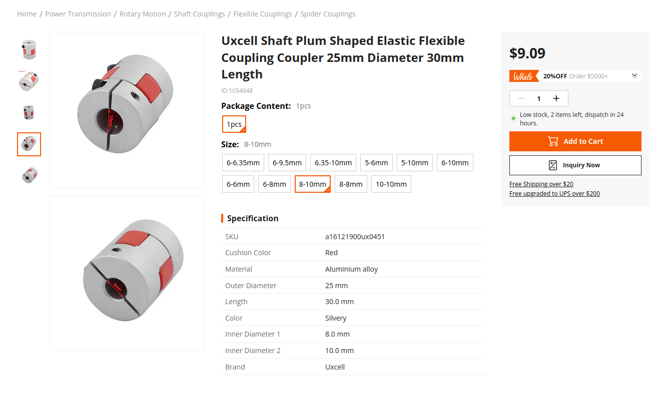
Next I needed to figure out what 8mm to 10mm coupling I should use and the model I needed to use it for. I spent like a solid 20 minutes trying to find a well price, yet well designed one and came across this nice coupling from Harfington (the supplier is Uxcell though).
It looks like it will get the job done, and I probably get free shipping on it, and it'll only cost me $20, I've also seen the Uxcell brand everywhere so I feel like I would just get a more expensive version of the same thing from the same place if I got something from somewhere else.
Now I just needed to find a model for this, the website didn't have one and I couldnt find the supplier website so I just googled it. The computers at my school kind of have google superpowers and I found a good one within like a minute on grabcad. It was the exact same specs and looked pretty darn good.
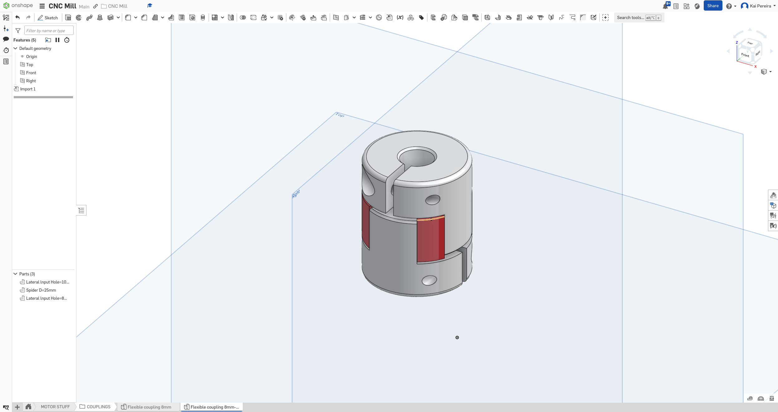
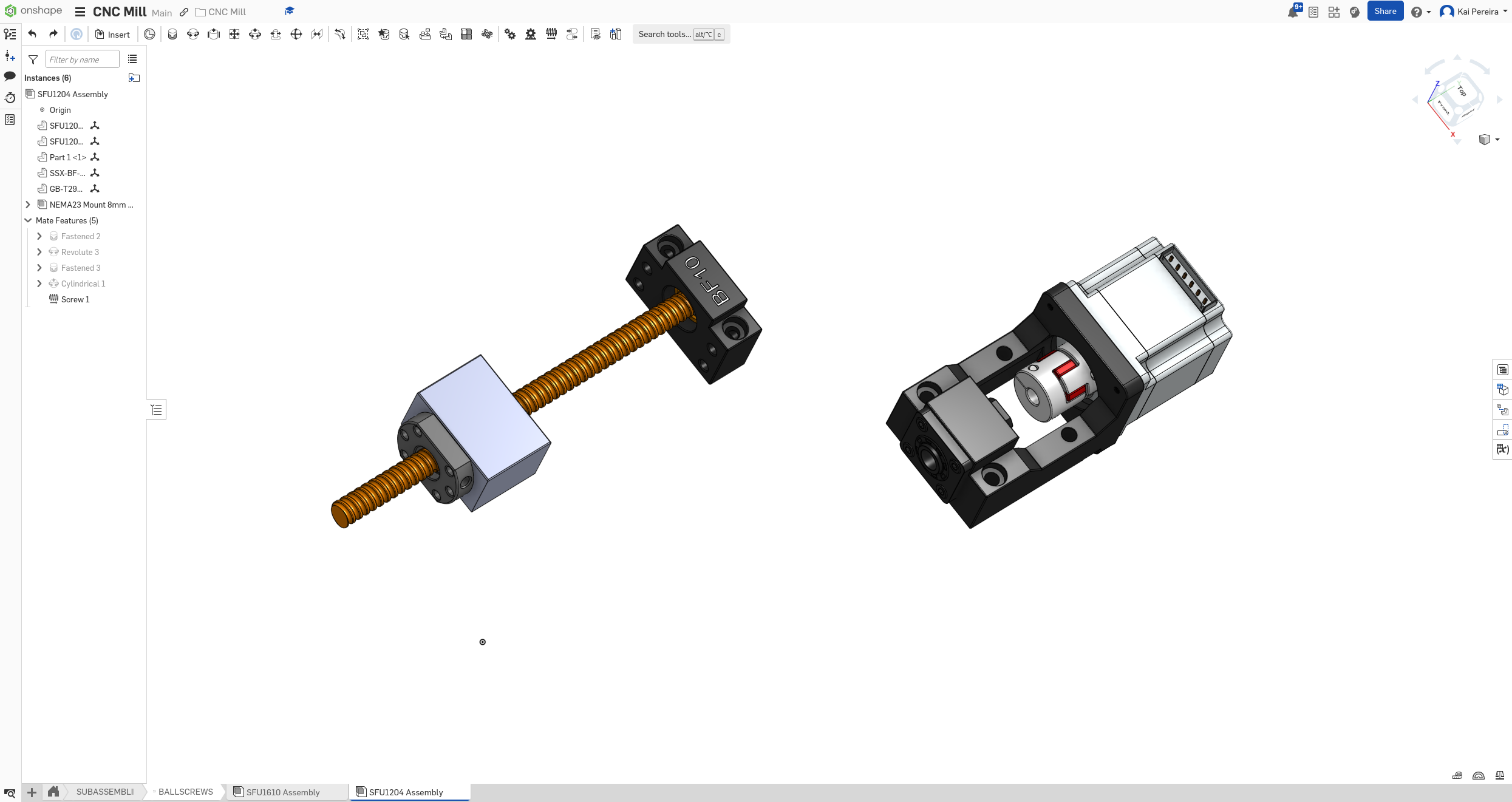
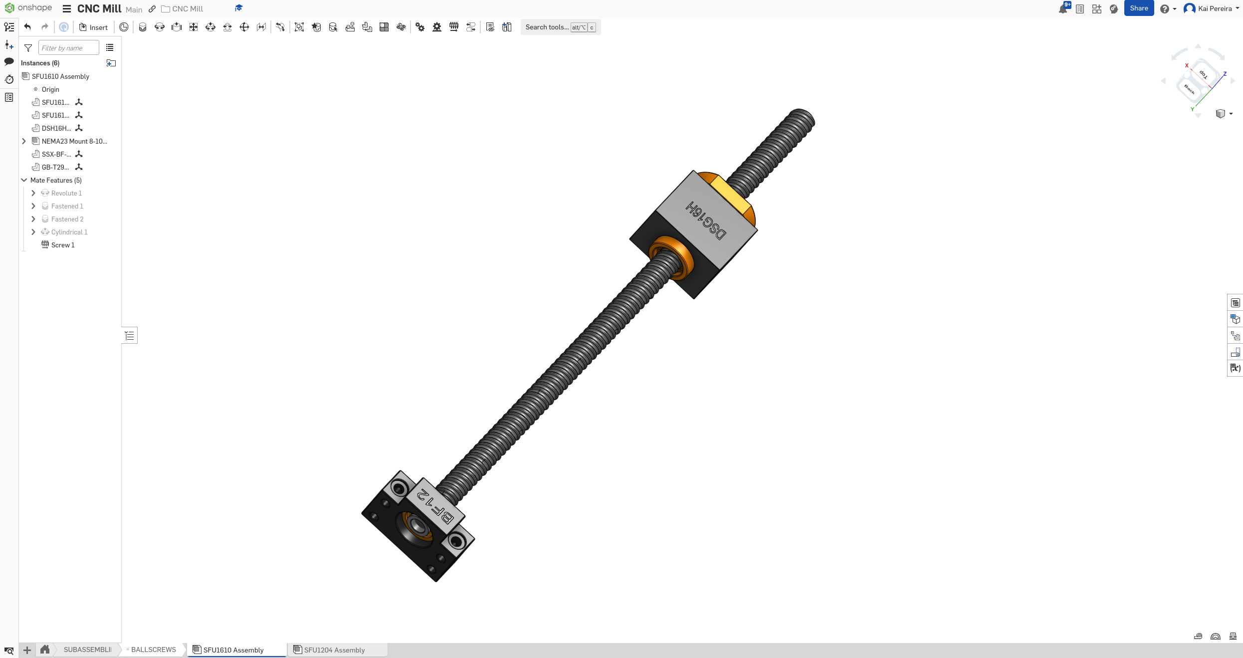
Then I just chucked a boolean on it to make it one part, then transferred it over to the assembly. Time to put all my components together now!
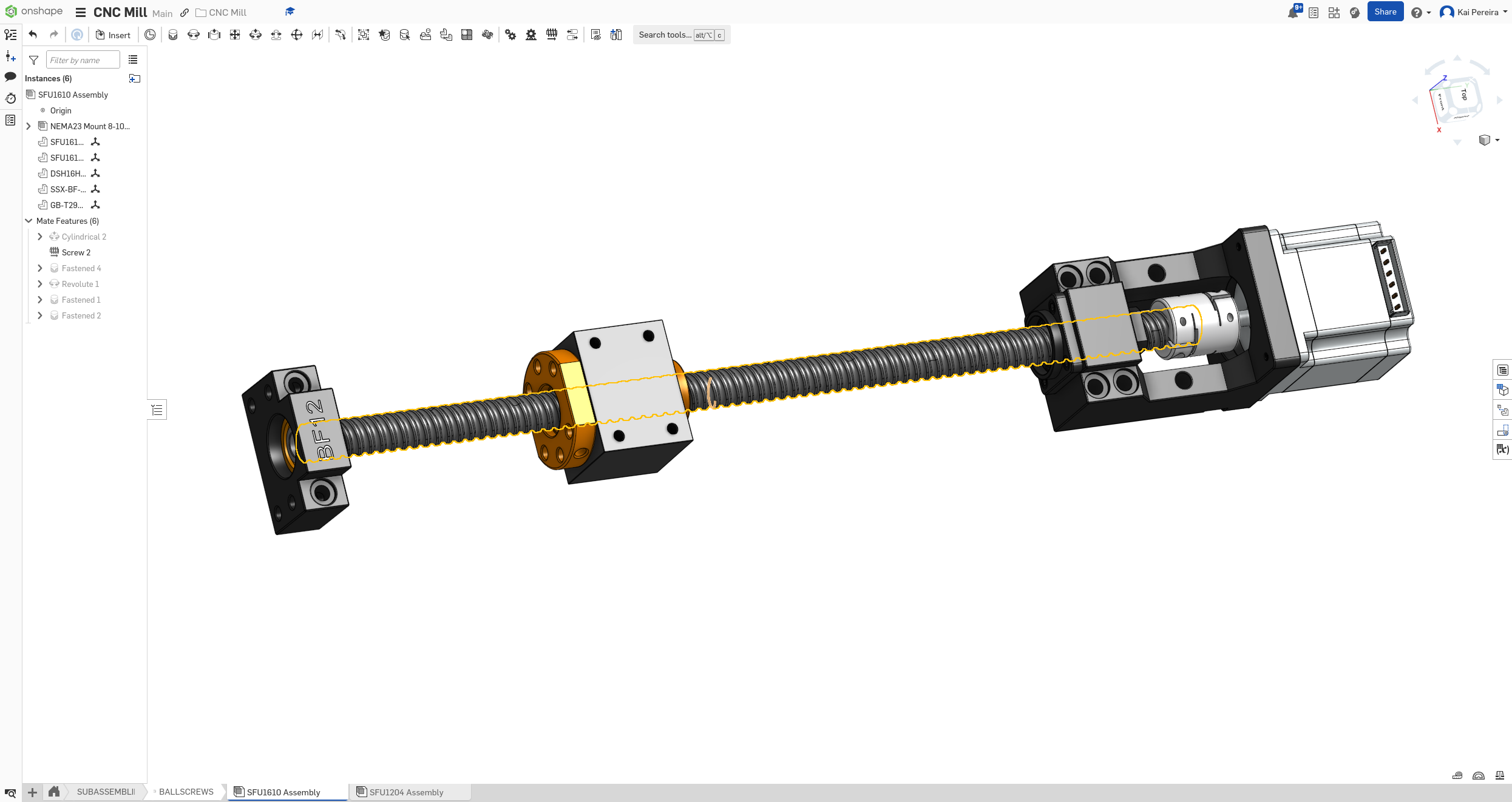
Both X and Y assemblies I think are going to use the same ball screw setup because they're the same distance, and the Y assembly is just all the components but slightly modified to fit for 8mm and to have more power.
The ball screw assemblies are just the: - Screw - Nut - Housing - BF support - Motor mount - Stepper motor - Flexible coupling
Put together to create these 2 beauties (video). (Also thank you HackClub for the free CDN)
My Z axis looks a little bit short, but I'll check it out when I start putting stuff into the bigger assembly and see how everything fits.
And yeah, that's everything I wanted to get done today, I didn't do anything yesterday because I had that Football game but today I got all that other stuff done. I only spent like an hour and a half, but I'll just count it for an hour and just next time I do another half hour, I'll count it in for simplicity's sake.
Tomorrow I have just one big goal which is to implement all the ball screw sub-assemblies into my main assembly, so we'll see how it goes!
Total time: 52 hours
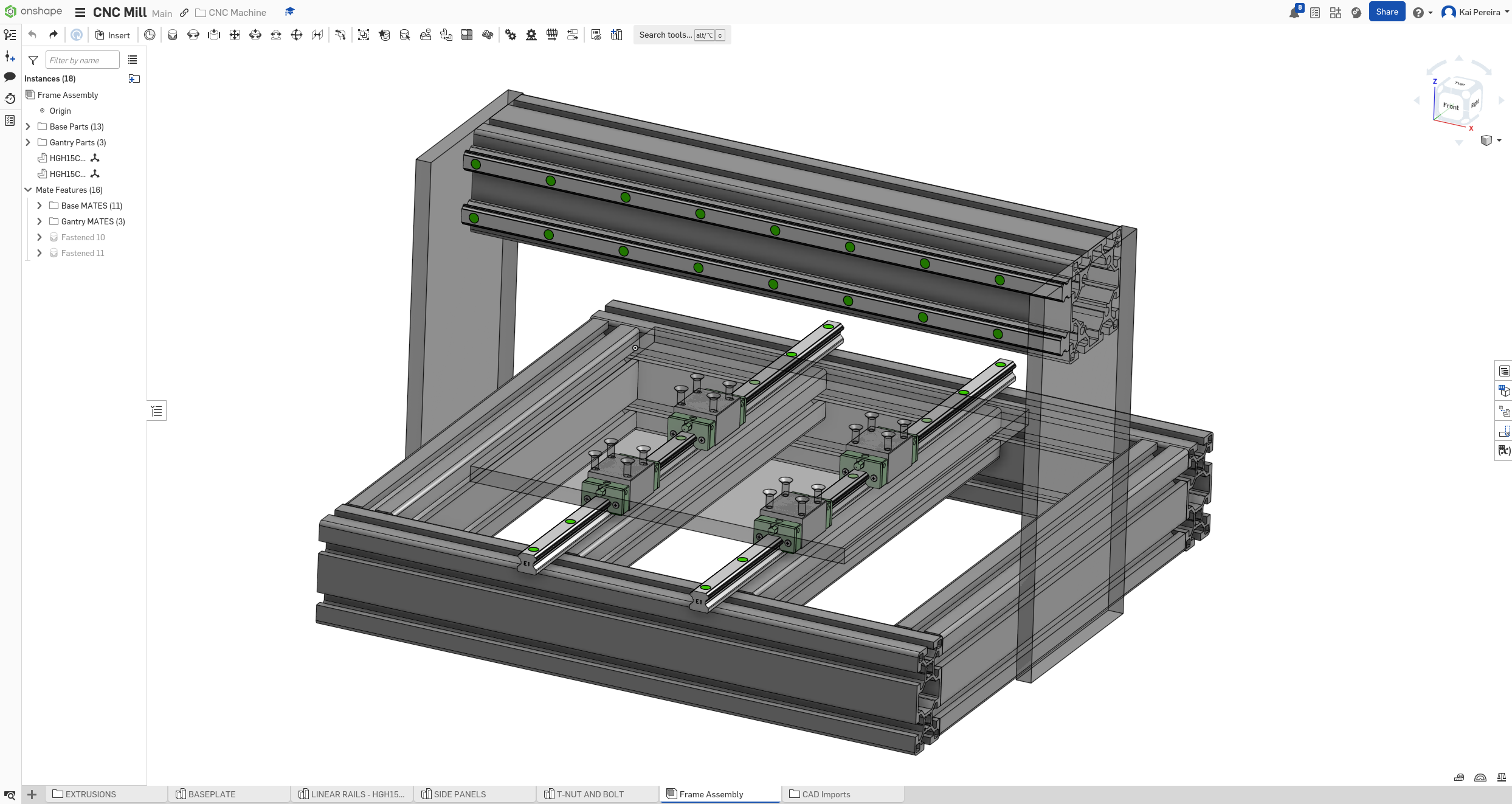
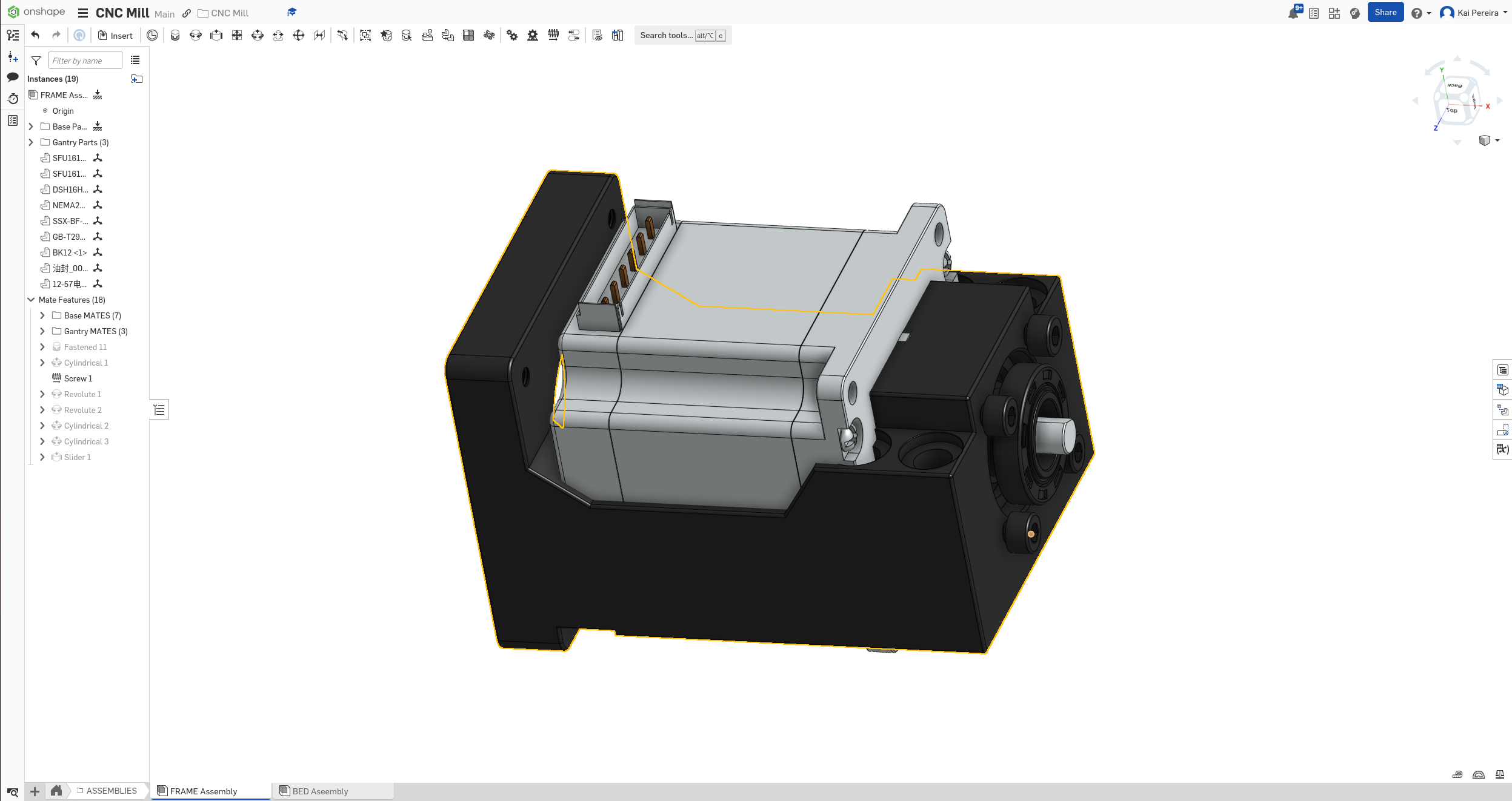
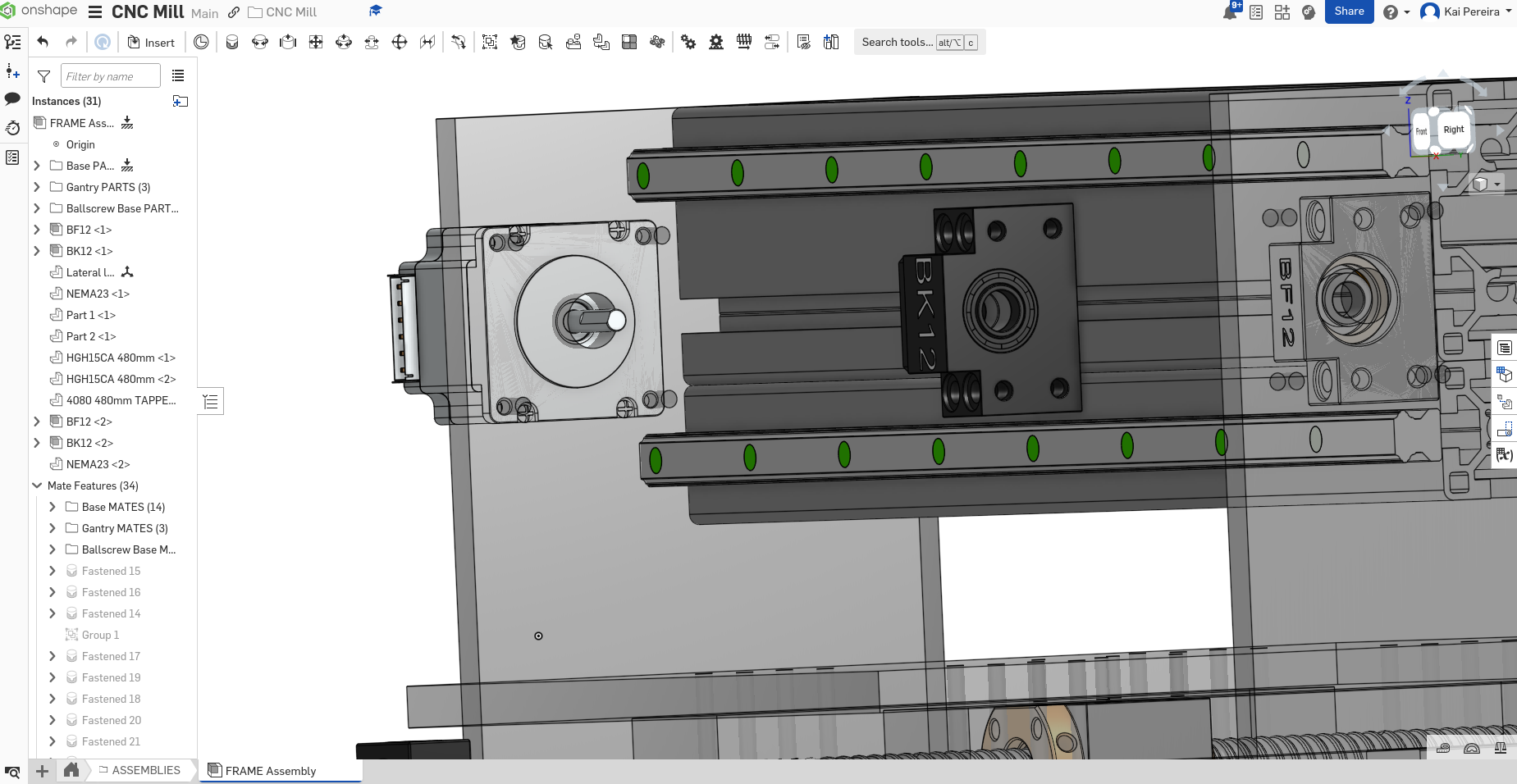
Day 18 - Main assembly
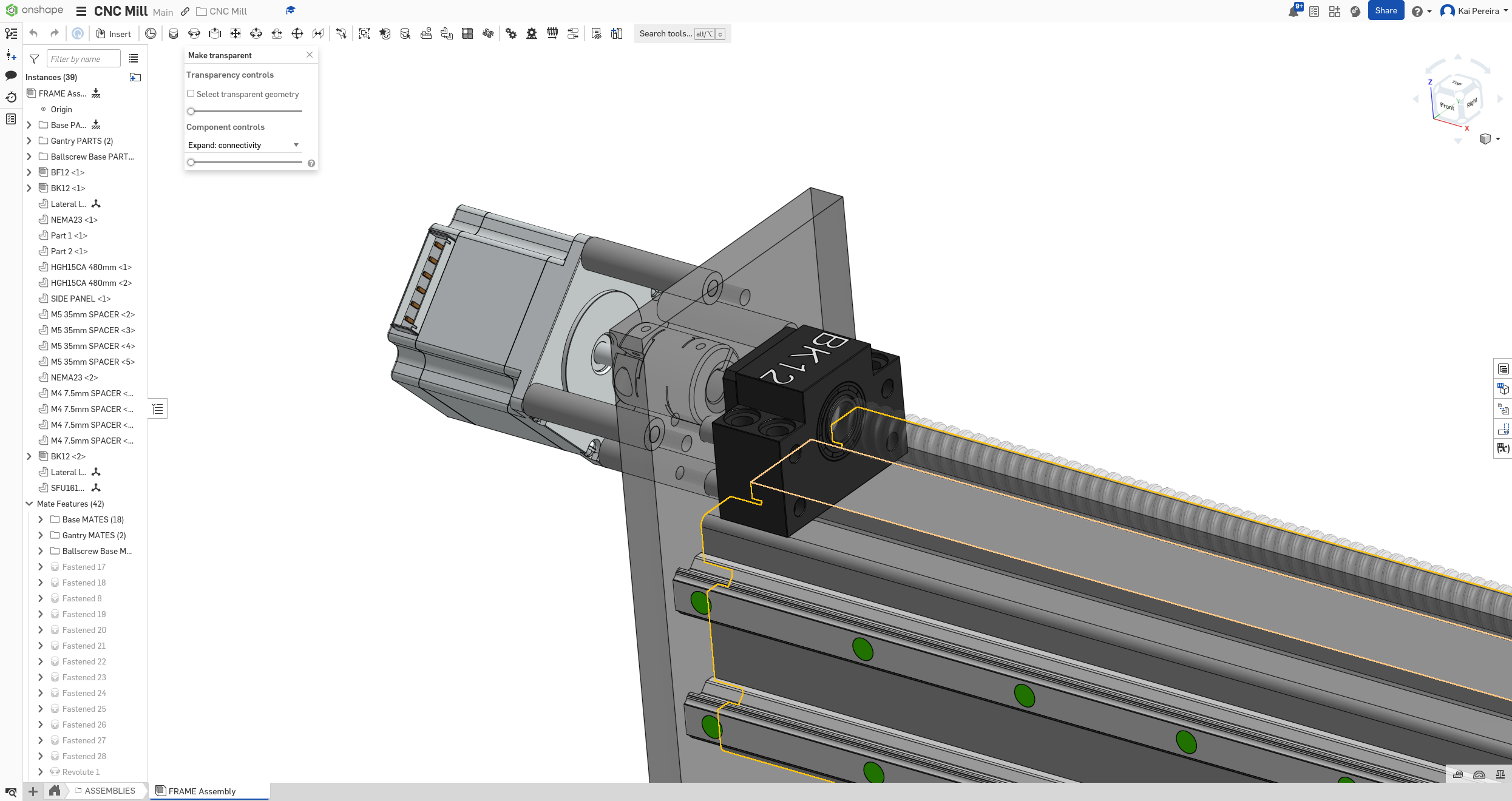
I really wanted to get some of the ball screw sub-assemblies into my production assembly so this was my main goal for today.
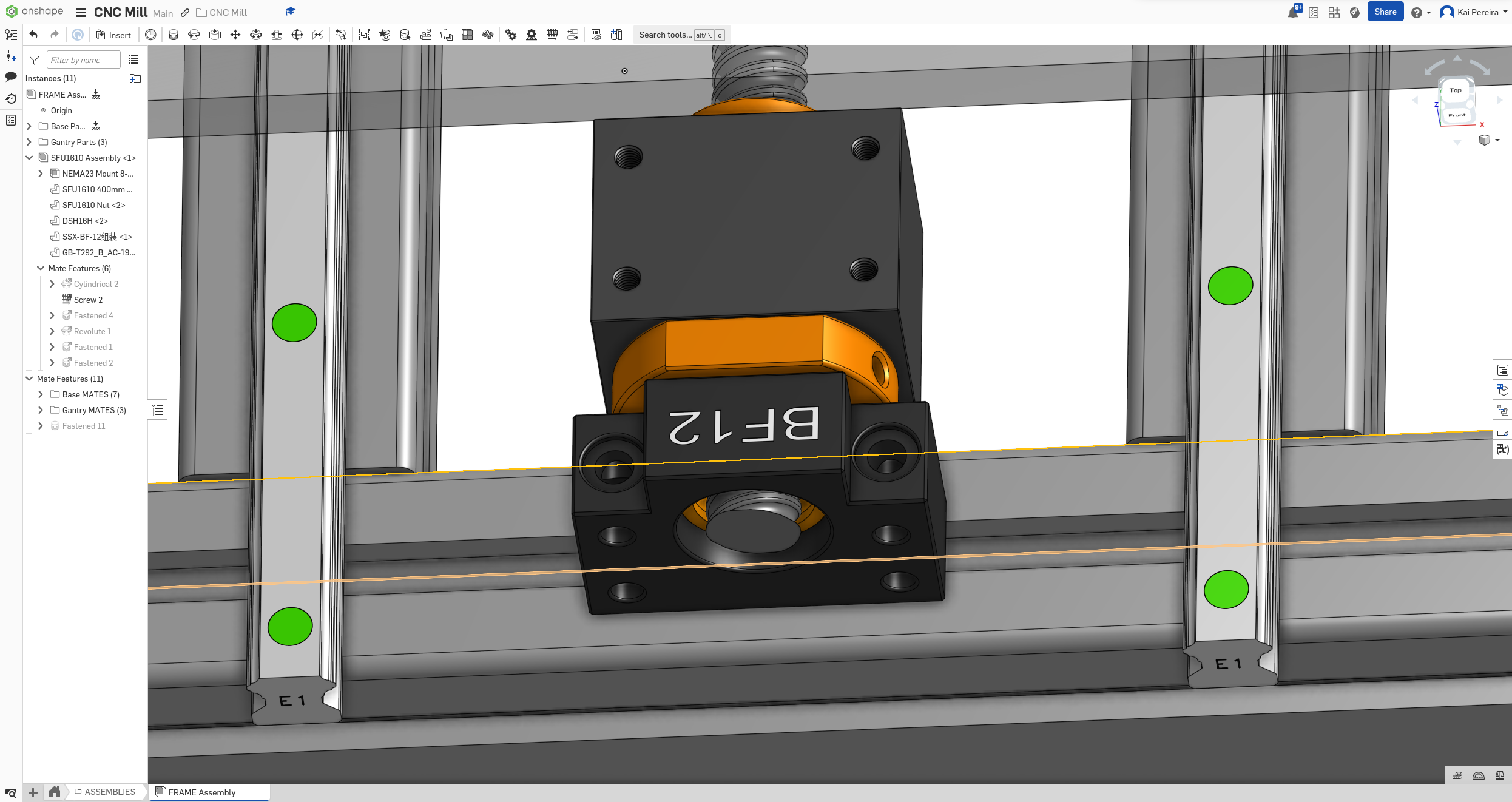
First I just chucked the models into the design, and then I fastened the BK support to one side of the extrusion because I knew I wanted this to be one of the connection points for the ball screws, and then a couple of problems arose: - The nut housing goes through the bed - The motor mount does not align with the extrusion on the other side - The ball screw wasn't aligned properly within the BK support and motor mount
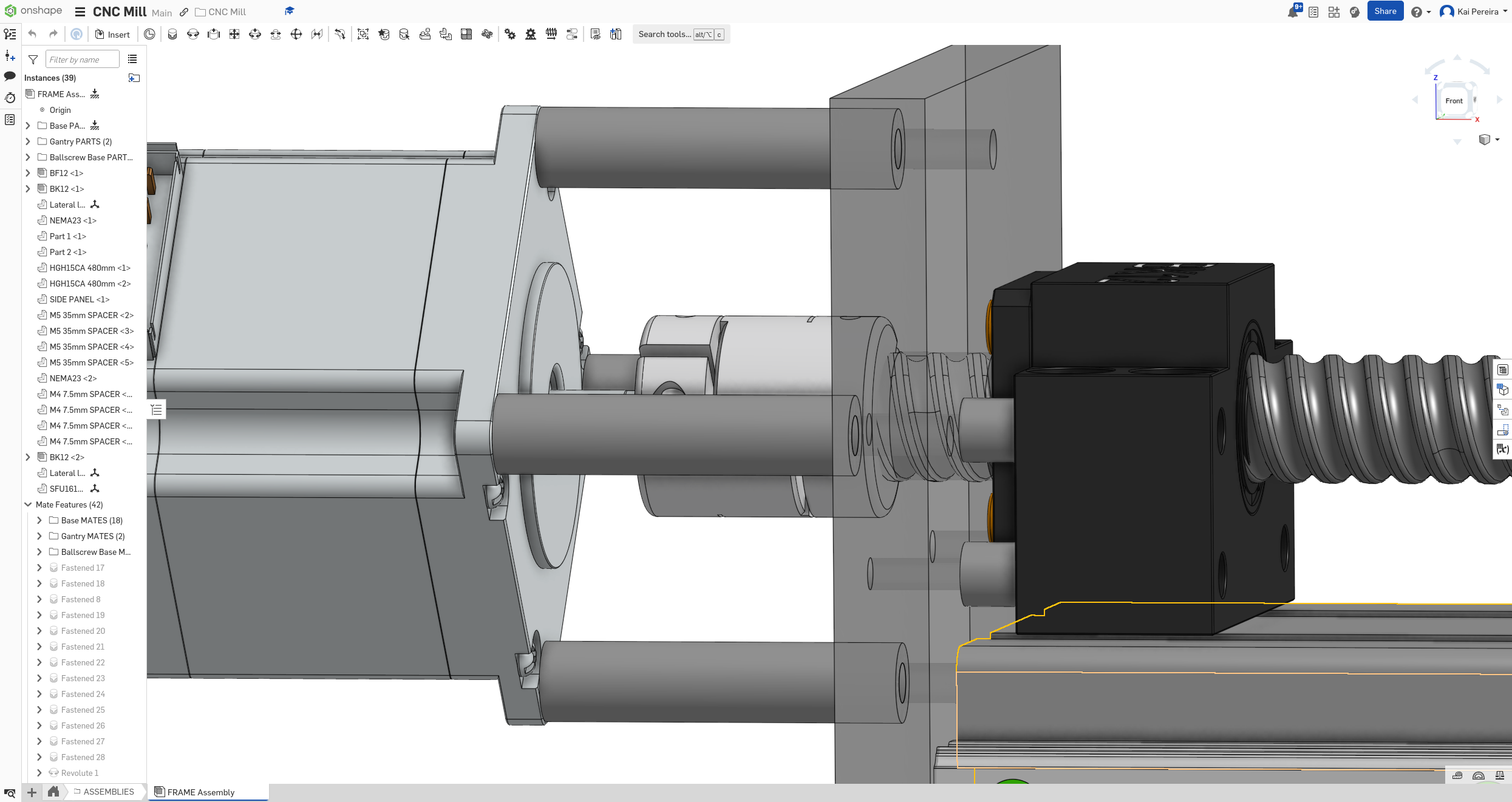
So I kind of had to fix all of these separate problems. First I worked on getting the ball screw aligned within the BK support and the motor mount. I kept on trying to find the dimensions of the ball screw leads but I realized this isn't actually what I'm looking for. I needed to look for the dimensions of the lead in the support/mount.
So I looked on the LIMO bearings website because this is where their manuals were for the measurements.
These docs were so convoluted that I decided that it maybe wasn't this. So I just did a quick google search and turns out, the ball screw can just align flush with the BK support.
But the motor mount was still a bit different. It needed to be within the length of the ball screw lead. But after looking at quite a few images, I think it's safe to leave it as it is with half of the ball screw lead into the coupling and half into the stepper motor. I'll look into this more though.
Now that was a bit pointless, but at least now the ball screw is aligned better.
Now that that was done, I needed to align the holes on the other side. I asked the PrintNC discord if it was fine to have only 2 bolts on each side and they said it was about the minimum rigidity needed, so I kind of want to bolt them in better, but for now, I'll just align the holes with the extrusion rail. I just increased the length of the ball screw and boom, it was pretty close. Shown in the photo above
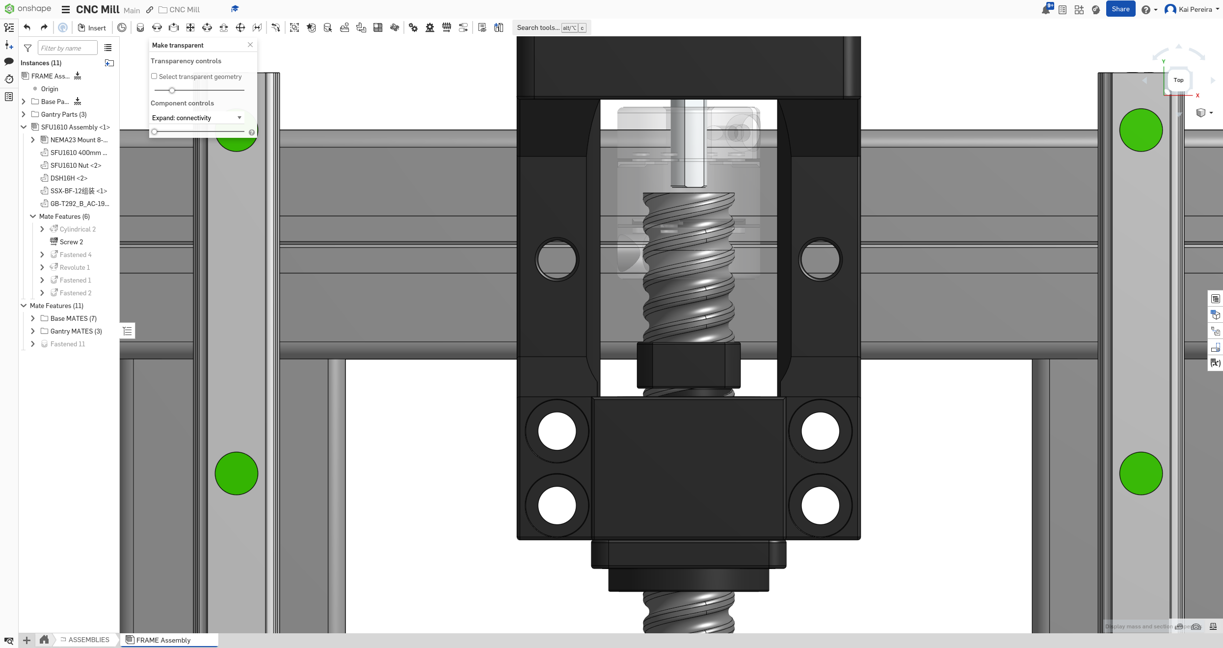
Now I have to tackle the ball screw housing going through the main bed. This is actually a pretty large problem and I have a couple of options: - Move the whole ball screw assembly not optimal obviously - Make the bed larger and then put an indent into it where the housing will sit into - a pretty good option if I dare say so, but makes the bed more expensive but maybe more rigid. - Find a way to decrease the level of the whole ball screw assembly to make it shorter. i.e decrease the height of the supports, make the housing and nut shorter, etc.
Honestly I kind of want to think over this a bit more because it's kind of an important decision, but I feel like the second option is pretty good.
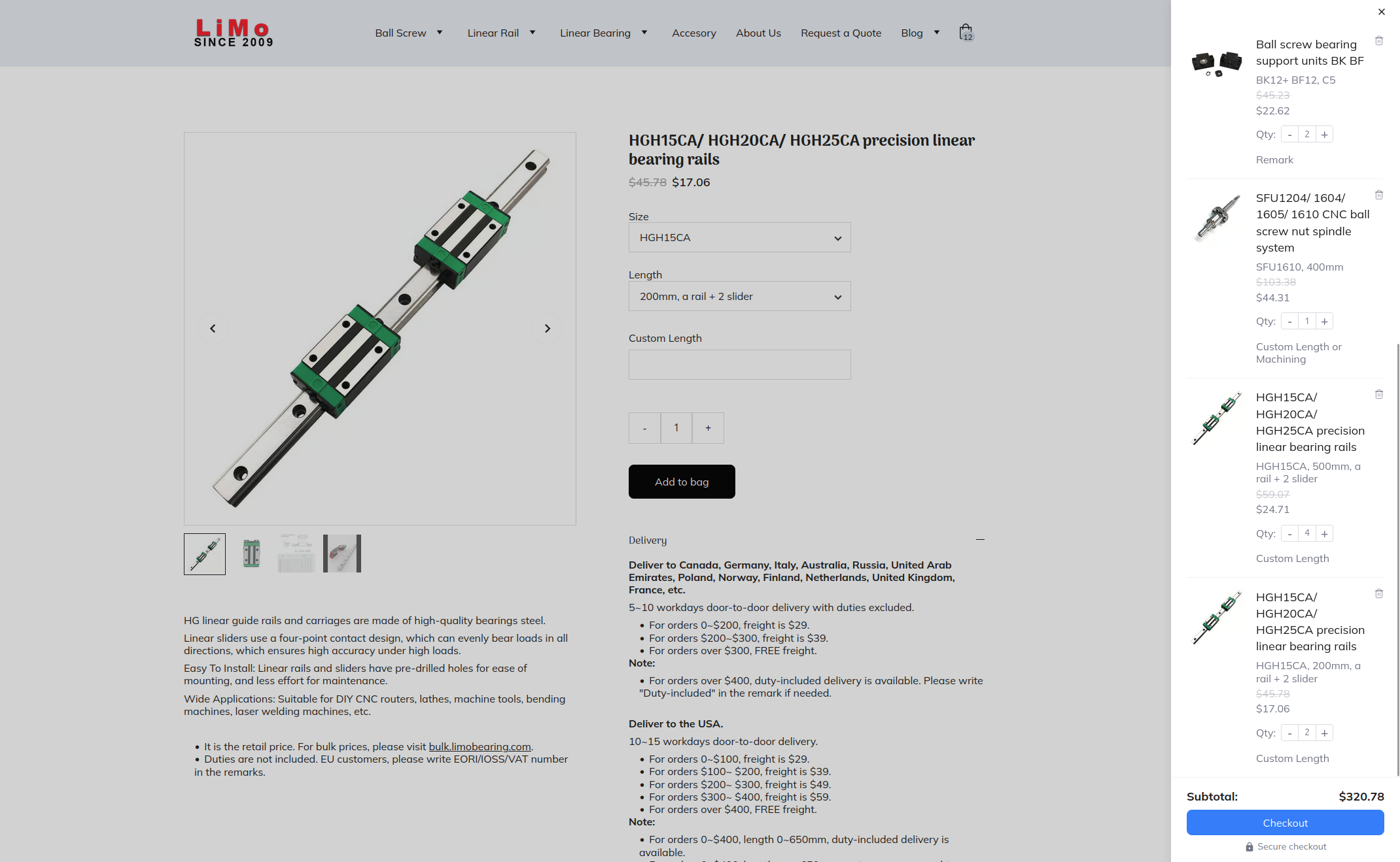
Anyways, while I'm procrastinating that I found 2 really cool things. First of all, I found that I could get a ball bearing assembly from LIMO bearings and it's cheaper than just buying all the parts. But sadly it's a BF support instead of a motor mount. But maybe I can reach out to them or look into using BF supports instead of motor mounts?
Another thing I saw is that 8020 actually has decently priced extrusions, it's similarly priced but I kind of have to compare them some more.
Anyways I'm kind of tired but I got some stuff done still, and I really want to wake up at 6am tomorrow because I'm very productive around that time so I'm probably locking out for the day.
Tomorrow I want to figure out how the housing should move the bed (because they're intersecting right now) and then do some double checks on whether the rigidity of the ball-screw is fine and if they're aligned correctly.
Total time: 54 hours
Day 19 - More bed ball screw shenanigans
I spent 2 days working on this but I got quite a bit of stuff done. I knew after day 18 that I need to fix the housing intersecting with the bed and to ponder the rigidity and costs of the setup.
First of all, I remember seeing that deal on LIMO bearings which was $50 for one whole set of the ball-screws I was using. This would LITERALLY BRING MY COSTS FOR THE BALL-SCREWS DOWN TO LESS THAN $150. This made me so happy, but required a couple modifications.
You see, this LIMO bearings set doesn't use stepper motor mounts, but instead just fixed supports. Now buying these instead of the separate parts would save me $100, so I needed to work out a way to use the fixed support instead of the motor mount.
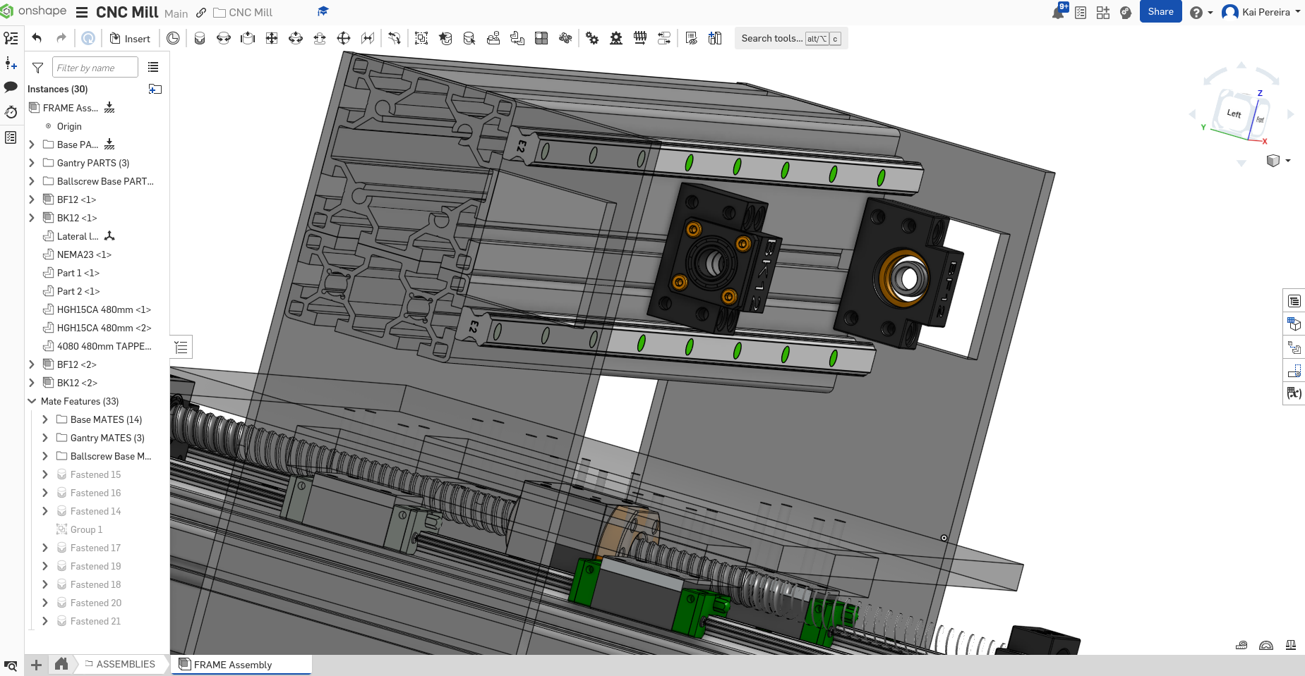
I knew that I probably wanted to attach the fixed end to the top of the aluminum extrusion, but this does pose some rigidity issues.
like so
I feel like this is the easiest way of mounting it, but not the strongest, so I might re-contemplate adding a plate or something, but this is really the best I could see myself doing, without wrecking any of the other things I needed like a large work area. I reached out to some people on the PrintNC discord and they said that it was probably fine to just bolt in 2 of the 4 bolts to mill aluminum, but I might need to upgrade for steel.
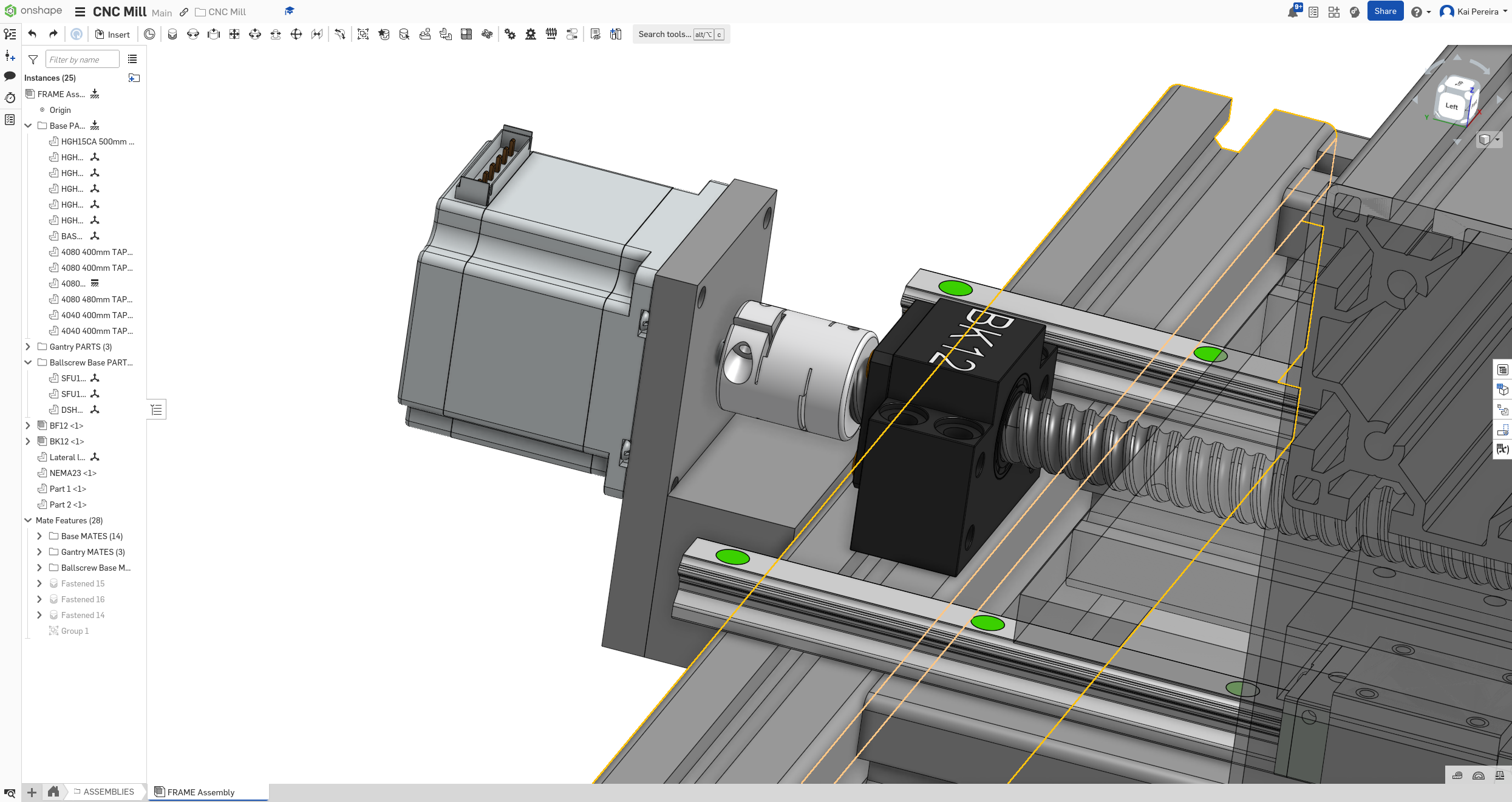
I feel like this is kind of cutting shortcuts, so I kind of want to figure out a way of fixing this, but for now, I had some even bigger problems. Because the flexible coupling needed to go from the end of the ball screw to the stepper, the stepper motor is quite far off the mill.
This means I have to find some sort of way of attaching the stepper to the extrusion. There's a couple ways I could do this: - A plate from the top of the extrusion bending upwards to connect with the screws of the stepper - A plate from the side of the extrusion and then up to connect to the screws of the stepper - Some weird support structure from the ground, I'm not too sure - Moving the whole structure
Honestly there's only 2 things I really considered which were the plate from the top and side of the extrusion to the stepper. I decided that a plate from the side of the extrusion would be strongest and most practical, I want to keep the evenness of the top so I don't really want a plate up there. And one from the side wouldn't be too hard to machine. I could just take some scrap aluminum, put in some holes with a drill, and then bolt it in, and then BOOM, we have this support.
I decided to dissolve all of my sub-assemblies (except the ones like BF and BK supports) because I needed to start attaching smaller parts of each assembly which just wasn't working when they were sub-assemblies, so now it's all just parts in folders, which I feel like is for the best.
But anyways, I needed to attach the ball screw to the bed now. There were a couple ways I thought I could do this so the bed didn't intersect the ball screw housing: - Raise the height of the linear rails - Decrease the height of the ball screw - Increase the height of the bed - Drill a hole into the bed to fit the housing into
All these options were actually pretty darn good, but I ruled out changing the linear rails and decreasing the height of the ball screw assembly for obvious reasons. Then I decided that drilling holes into the bed probably wouldn't be the easiest, so I ruled out that too. Raise the bed it is.
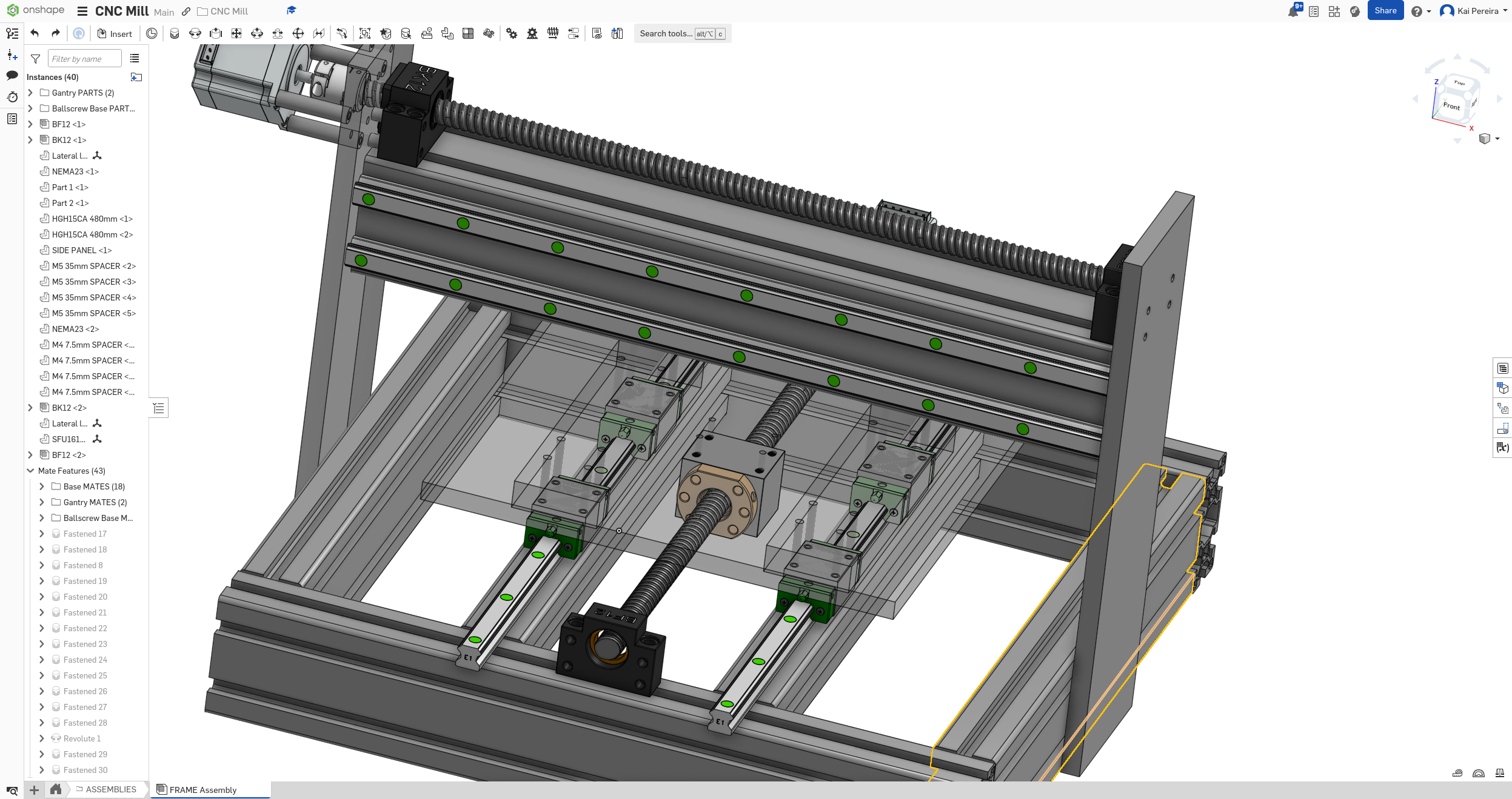
It actually took me a while to find this kind of design where you raise just the sides of the bed, but I really like it, because I can just attach scrap metal to the bottom of the bed on each side and it forms a little bridge.
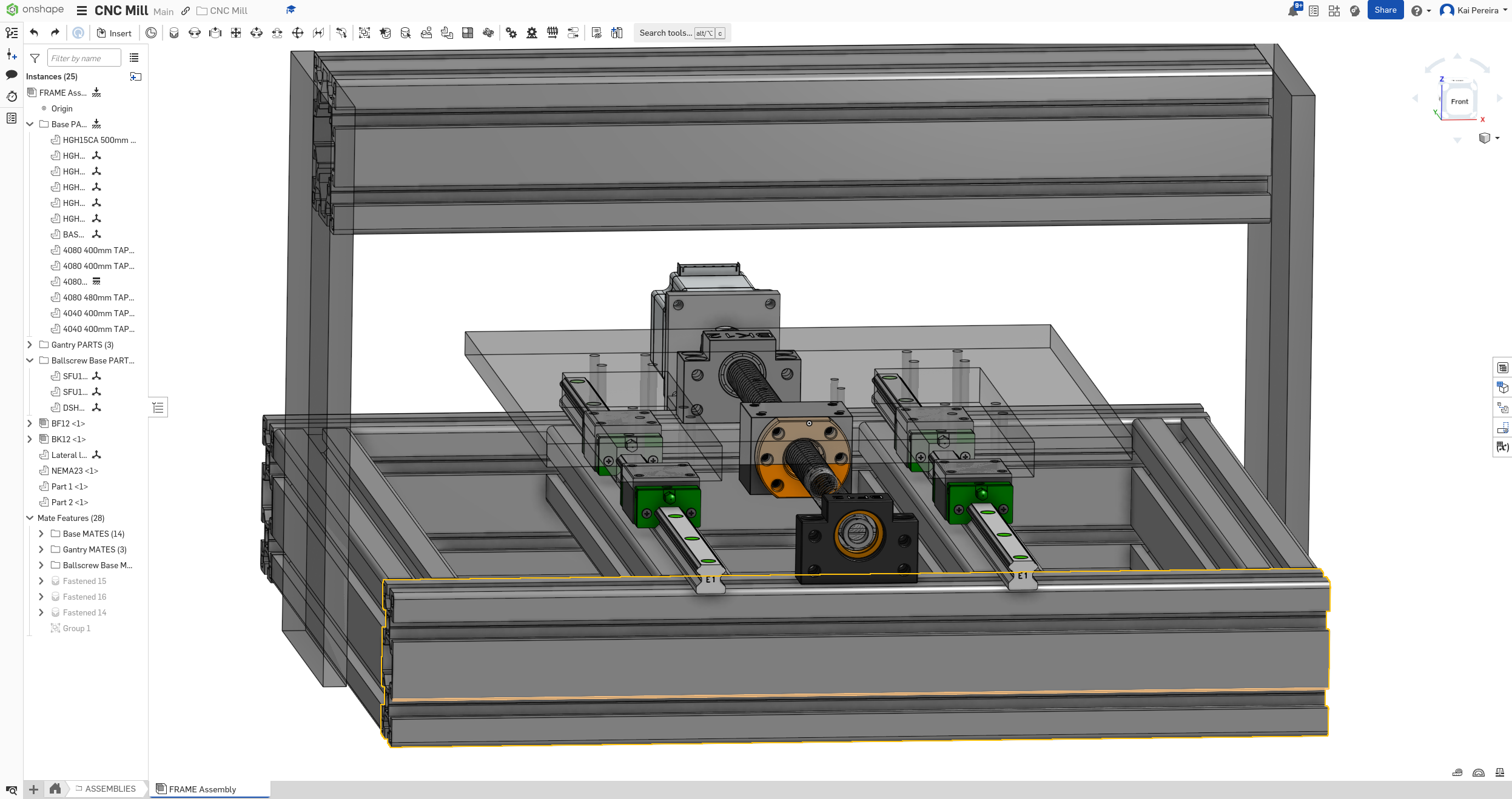
And now I can just bolt through both the bed and the plates to make it very rigid and it works pretty nicely on a budget.
And now I have ANOTHER problem. So the bed is moving, it's a giant chunk of aluminum moving, so it's bound to hit something right?. Well turns out, it's hitting the stepper motor.
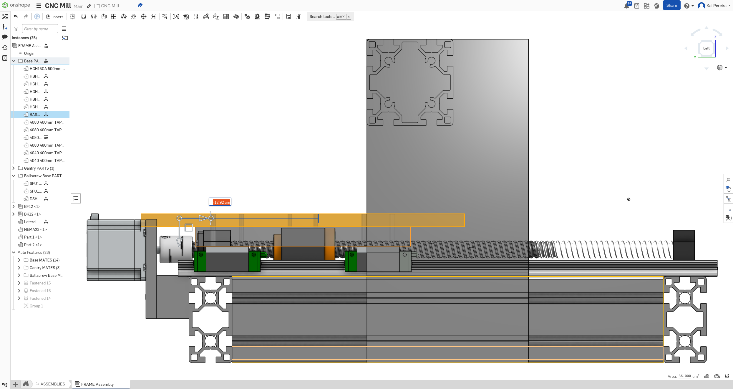
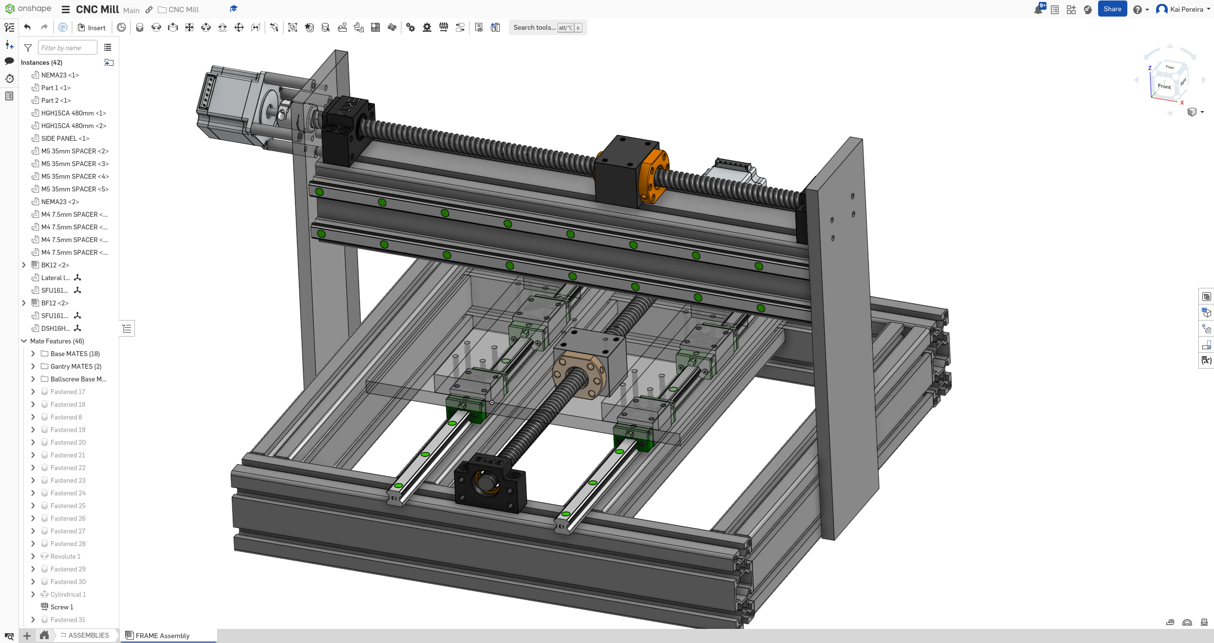
I actually about perfectly get 30cm of travel for the ball-screw but I really want 35cm because it fits within the constraints of the mill. Now I'm not actually too sure how I want to do this, there's a couple of ways I could go about doing it: - Raise the sides of the bed even more so the bed goes over top - Increase the size of the ball-screw - Something a bit more crazy like moving the stepper motor and then using gears
Honestly I'm still considering my options, but raising the bed seems like the easiest way. But honestly, I have my 30cm of travel, I might start working on something different to keep my brain occupied, and to stop the burnout.
Another thing I wanted to mention, is I have some really iffy assembly connections relating to the bed which would be nice to fix, but I haven't really found out how to fix, so those would be nice to finish too.
But anyways, I did a LOT of brainstorming over these 2 days, to come up with intuitive solutions to the bed problems, and now the other axes should be easier to assembly. Because of the space constraints of the bed, it's really hard to work with it, so I feel like the X axis will be easier.
Tomorrow I really want to continue working on the gantry and getting the X axis in. I'm not too sure about using that piece of 8080 up there, but it does work well, so some more stuff to think about. So yeah, X axis tomorrow and some gantry shenanigans.
Lots of good work done today, but I'm still falling a bit behind on this project so I really want to get grinding tomorrow, procrastination has been getting the better of me, so I really have to power through.
Total time: 57 hours
Day 20 - Gantry go Brrrrrrr
Time to get working on the X axis! The X axis is much more simple to design because it's constrained between some walls and the rails can just ride on the extrusion.
First I'm just going to put in some rails going from one end of the gantry to the other on the extrusion.
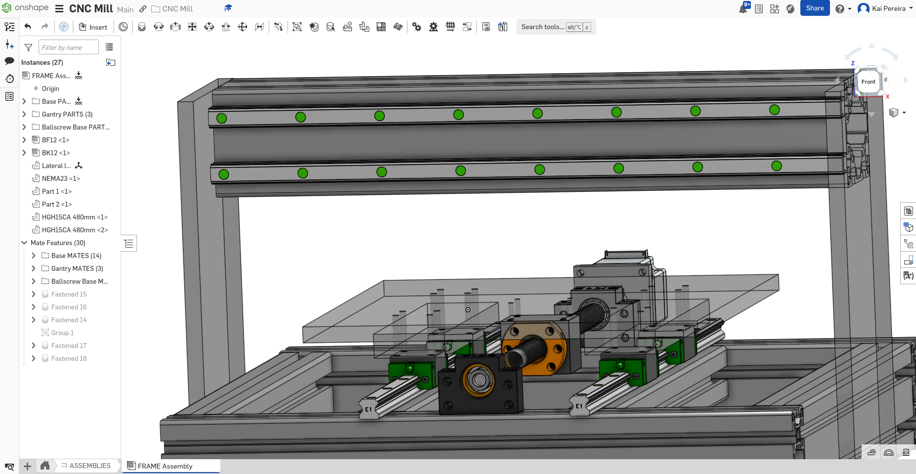
I switched to just my laptop here so the images might look a little funky
Now I'm pretty sure it's best to put the ball-screw between the 2 sides of the gantry, so the faces of the supports touch the sides, that'll make it very rigid.
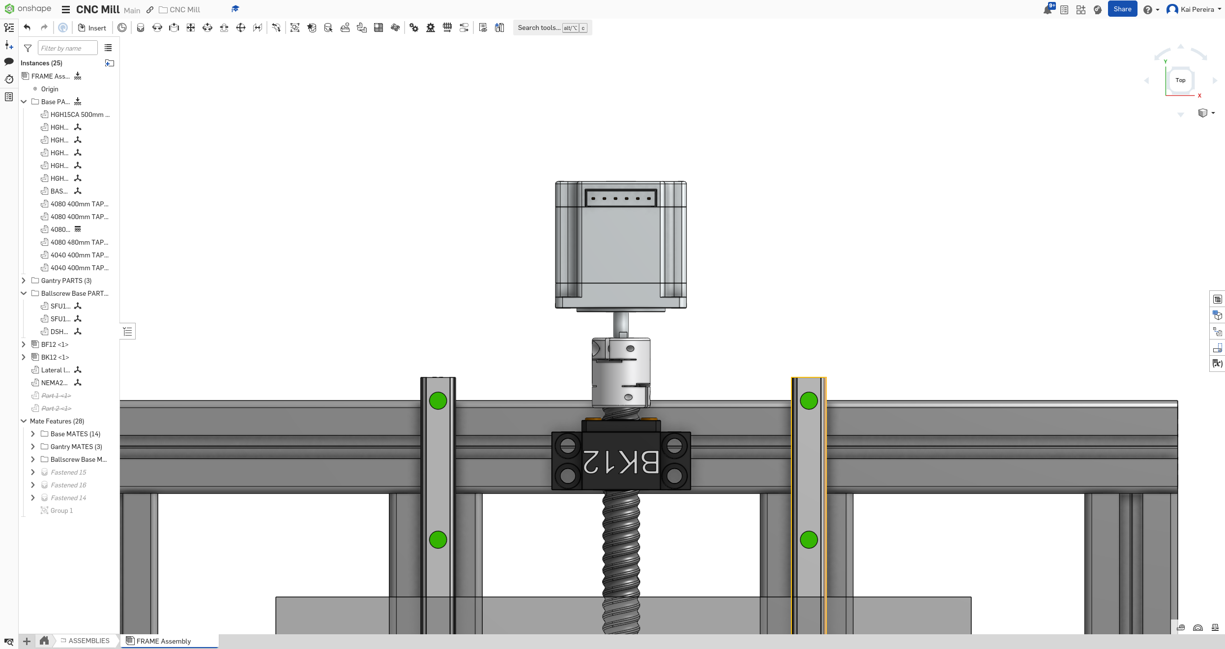
Anyways I added the supports, turns out the BK support can't exactly touch the walls because the stepper still has to attach to it, and the stepper is attached to the side through it's screws. So for now I'll just leave it in the center until the coupling and stuff is modeled in.
Now I have to add some screw holes into the walls of the gantry.
Quick math: The extrusion is 8cm long, and the center of the motor will be the center of both extrusions, so down 6cm.
Now just have to add the screw dimensions in and BOOM, we have the mounts for the motor.
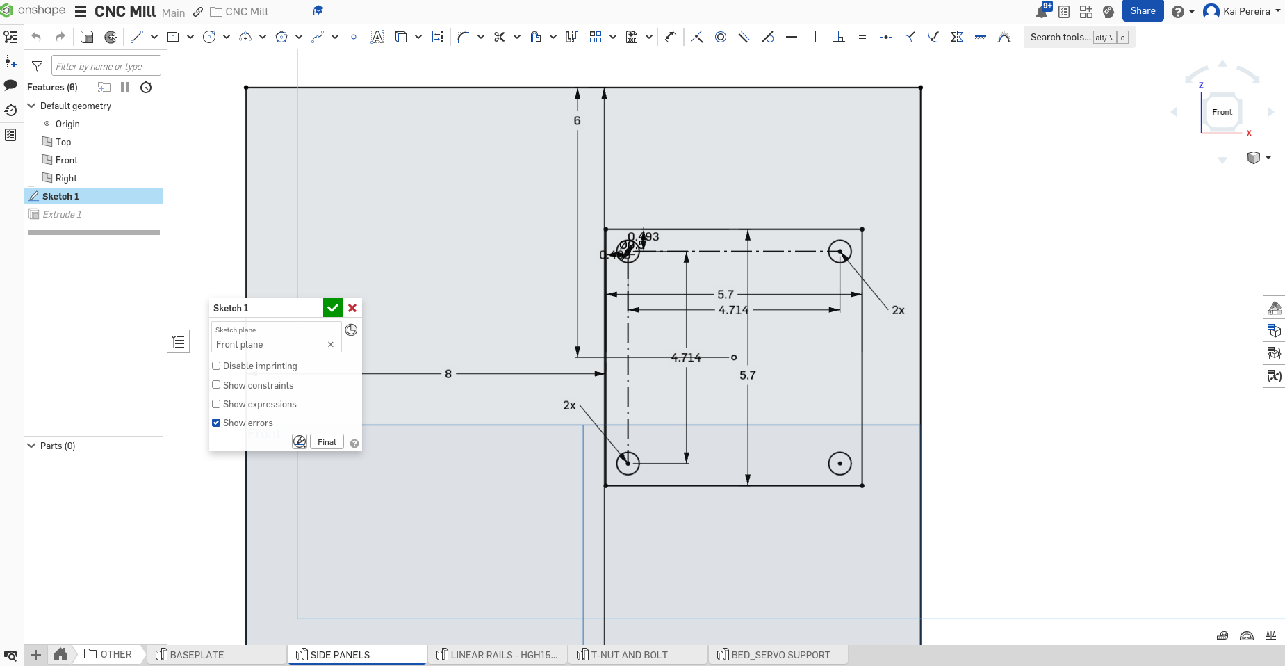
Now I just have to add a center hole for the motor so that the shaft can go through, I'll just make this like 16mm or something like that so it fits the shaft nicely but maintains structural rigidity.
Now I'm going to add the coupling to the servo and then the ball-screw. My ball-screws seem bugged right now though, so I kind of need to fix those, I'm going to look through my history first and then if that doesn't work, I'll just re-import them.
Okay I managed to fix it by literally just editing and un-editing them so I think it was just bugged.
I kind of want to figure out what I'm actually going to use for the gantry beam though, so I might do a bit of a brainstorming session on it. There's quite a few options I could do from what I could tell: - 80/160 extrusion (rigid, expensive) - 8080 + 4080 extrusion (smaller, cheaper) - 8080 +8080 (rigid, mid-price) - C-Beam - 1 or 2 pieces (easier to work with, cheap?, not as rigid) - Large slab of steel tubing (Rigid, cheap, hard to work with) - Large piece of 100/100 extrusion (decently rigid, mid to expensive price)
Alright so I've spent about 2 hours figuring out kind of the style of gantry I want. It's going to be a piece of 8080, with 2 rails mounted on the face, and a ball screw mounted to the top. The side panels will extend up to connect the ball screw supports and spacers will be mounted for the motor.
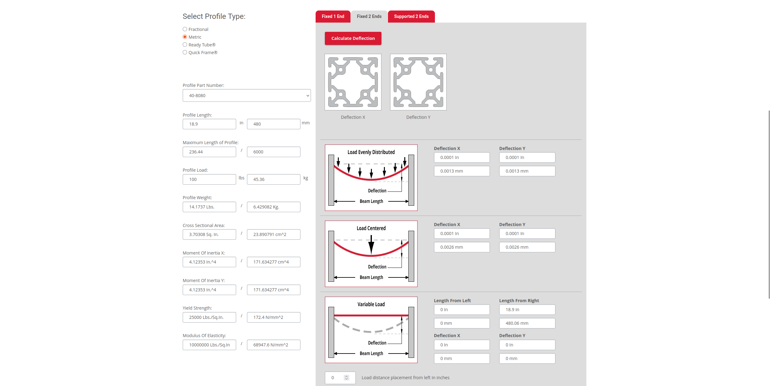
I calculated the deflection of the 8080 under all this weight and it holds up well, even up to 100 lbs nicely so it should work well.
You don't want more than 0.075mm of deflection on a given axis, and mine comes down to just 0.0026mm at the MAX which is pretty good.
Now I just gotta model this in. First I'm going to delete the current ball screw just because the new one is mounted a bit differently. I'm going to move the side panel holes and add some standoffs like so:
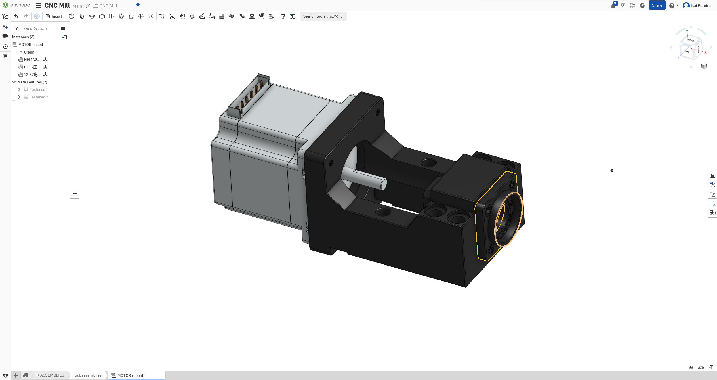
I then need to mount the stepper motor onto the standoffs like so:
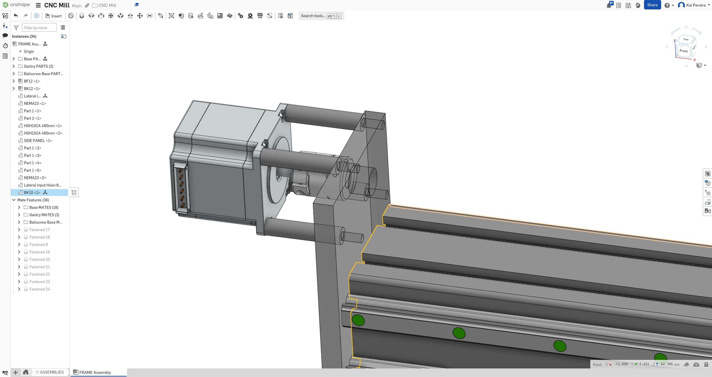
And then add the BK support fastened to the wall. A problem arose when I did this though, the screw holes of the BK support, lined up with the screw holes of the stepper motor spacers. This means that I wouldn't be able to actually bolt them in properly. It took me about a half hour to find a cool solution to this, but I came up with this ingenious design.
I mounted the motor at an angle and then just attached the support like normal. This means that the holes will line up differently, while keeping the BK 12 support in line.
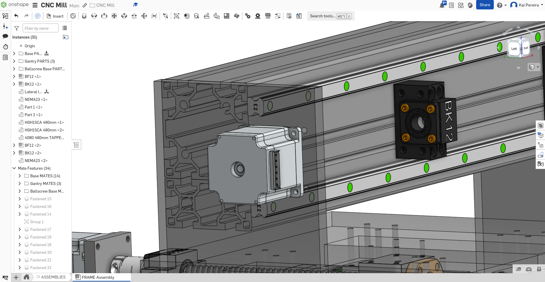
Now the BK support has to attach to the wall but also face a certain way. The larger end needs to be facing the stepper motor, so I can't just directly bolt the face of the BK support into the side panel. So I decided to just add some small 75mm spacers.
Now I'm just going to finish adding the ball screw and BF support like so:
Side tangent: working with the current ball-screw part studio is sooooo laggy so it takes a while to make them longer and such which is SO annoying
Time to add the nut and housing now!
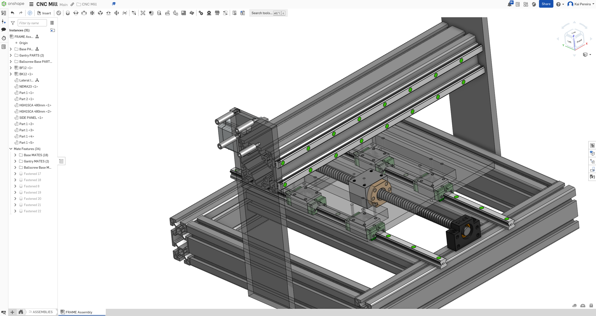
AND BOOM we now have ourselves most of the gantry. Now I really just have to add the carriages onto the rails.
1 minute later
Now our gantry looks sick asf.
Now I'm curious if this gantry will actually be rigid enough. I've run the calculations and the deflection is fine, but vibrations and whatnot might not be okay. Maybe I'll reach out to the good folk on the PrintNC discord for some advice.
Anyways, I spent wayyy too long working on that, but it looks so beautiful and it's a design I haven't really seen yet. Most people don't use 8080 with a ball-screw to add rigidity, and the stepper motor mount design is pretty cool. The linear rails do seem a bit close though, but I think it's fine because the ball-screw gives more Z travel, and because the length of the gantry is pretty short, it maintains quite a bit of rigidity.
While implementation was pretty simple, I spent soooo long brainstorming solutions to all the problems I faced while building it and it looks pretty good. Finally I can bring out this section of the journal after like 3 days of procrasti-working on this.
Now for tomorrow, I want to figure out how I'm going to attach the ball-screw to the spindle plate and work out the logistics on the spindle too. it would be SICK to have the ball-screw facing towards the spindle plate and then just moving it from there, but I'm not too sure if it's actually feasible, but it would make my life easier.
Anyways, I'm glad all that stuff is out of the way, and I can add lots of hours I worked on this to the journal!
Total time: 63 hours
Day 21 - Some spindle action
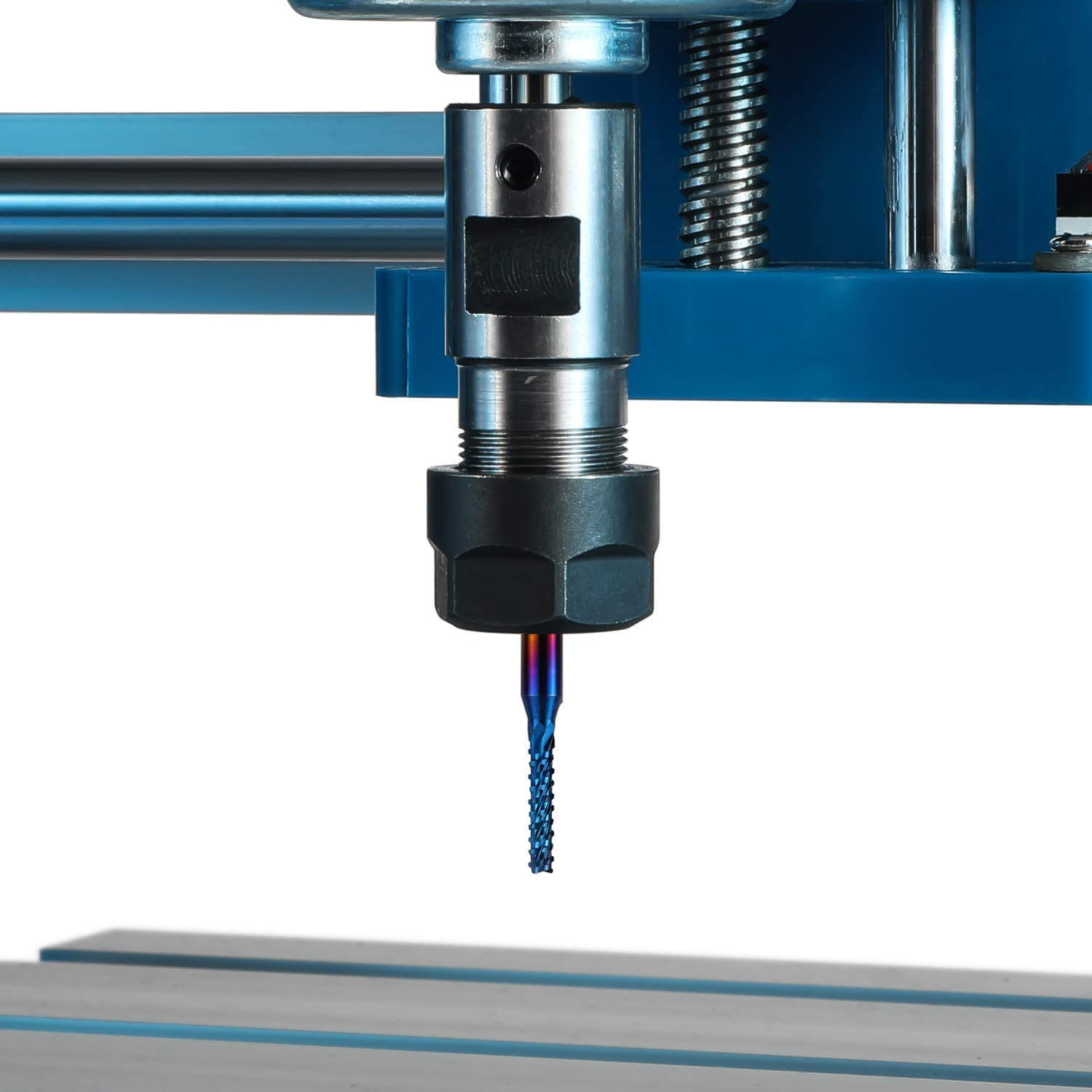
Today I really want to figure out what spindle I'm going to use. It has to be a decent price, rigid and also be able to mill aluminum. I remember seeing somewhere that a 2.2 KW spindle would work so I guess I'll start researching there.
Now I don't actually know exactly what I want, but I have some minimum requirements.
- Has to be 1.5 - 2.2kw, this gives it enough power to mill through aluminum comfortably
- Must be a water cooled or air cooled spindle, milling aluminum will heat up the end mill quite a bit so it needs to be cooled.
- Has to be less than $150 CAD to fit within the budget
Note: an end mill is basically the cutting bit
After a bit of research, I'm definitely leaning more towards an air cooled spindle. This is because a water cooled spindle requires lots of extra components like: - VFD - Water pump - Cooling water - Water hoses - Mounting stuff - Radiator/fans
While an air cooled spindle is basically just plug and use. Water cooled is better in general because it dissipates heat more easily and is way quieter, but for my case, air cooled will work out more nicely.
I feel like I can also modify my mill if I really want to change out the spindle and it would be pretty easy, albeit a bit expensive.
Water cooled spindles will also require a collection system and cleaning up wet pieces of metal seems kind of like a pain to do. So I think air cooled is by far a better option for now.
Now you can't just plug the air-cooled spindle into the plug and call it a day, you need a couple of things for it to work: - The actual air cooled spindle - The VFD (Variable frequency drive) - controls the speed and allows the CNC software to use the spindle - Collet nut - the end-mills attach to the collet nut to secure them in place - Spindle mount - the spindle will mount onto this, this probably needs to be a panel of aluminum with cuts (maybe 12mm I'm not too sure)
Now I'm pretty sure I can get all of this under $150 USD, which puts me still at around $600 USD for my total budget. Right now it's about $150 for ball-screws, $150 ish for linear rails (I think less actually), $150 for the extrusions, $150 for the spindle stuff, seems pretty straightforward. I'm just a bit worried about the rest of the electronics now so maybe I'll work on some budgeting.
After nearly an hour of learning more about spindles and researching them, this is the best spindle I've found so far. It's 2.2kw air cooled with an ER20 collet and support 110V. Sadly I want one that's a bit cheaper though. I've heard great things about this spindle though so maybe I can find it for cheaper.
There's also something like this from aliexpress which is $140 CAD for a 1.5kw, saving me about $30, but is it really worth it?
Now I've done a LOT of research the past couple days just learning about spindles (and how expensive they are) and I'm really tired so I'm just going to end it here.
Total time: 67 hours
Day 22 - Re-considering spindle choices
Optimally, I would really like to have a 2.2kw air cooled spindle, but the thing is, they're just too expensive. If you factor in the extra cost of the VFD, larger mount, collet and whatnot, it just adds up to over $250 CAD. I really don't want to also get something that's low quality, or just get flat out scammed so I'm re-considering some of my spindle choices.
I actually am leaning more towards the 1.5kw air cooled spindle for a couple reasons: - It can still cut aluminum and a bit of steel, which were my requirements. I just takes longer to cut and I can't mill like that much steel - It's definitely cheaper, taking account the smaller cost of the mount and VFD, the cost of a 1.5kw spindle will be way cheaper - Weighs less so there's less weight on the gantry and I don't need as strong parts to hold up the gantry and whatnot
But there's just as many downsides compared to the 2.2kw. Honestly having the 2.2kw would be very nice, but because of the fact that it costs nearly $75 more is a bit crazy. Also lots of the brands of these cheaper brands aren't very good quality. Another reason why 2.2kw is kind of not needed is because the actual power of the spindle vs how it's advertised.
Lots of the chinese spindles and stuff can't actually reach their top speed and end up performing just slightly better than a 1.5kw spindle. Another thing is, the larger spindle needs LOTS of current. I'm talking 20 amps of current at 110 volts, which might literally just trip my breaker which could be pretty annoying and take up lots of my time to fix.
So overall the 1.5kw spindle will be more reliable, higher quality, cheaper and will probably be better long term. If I ever wanted to upgrade and use this spindle for a different project I could for just like $200, so it's not a massive decision. If I still find a good deal on a more powerful spindle though, I might cope it on marketplace or something, but I'm still learning more towards a 1.5kw spindle after all my research. Maybe I'll also be able to find a nice kit that includes the VFD and whatnot with it too, which would be pretty sweet!
Time to do lots of searching...
Lots of the time spent working on this project is really just part finding, so when I got to build a project like this in the future again, it's going to be 100x easier because I already know a LOT of different parts and stuff.
After a bit of researching I accidentally came across this spindle which is only $112.50 USD for a 2.2kw air cooled spindle from bulkman3d which is a decent brand. I'm going to look into a bit more though because I'm skeptical of the price.
Anyways looking at spindles is a bit boring so I want to take a second look at the gantry. When looking at spindles, I've come across lots of information regarding rigidity of the gantry, and the current state of my gantry seems to have a couple problems. - The ball screw is on the top which isn't optimal, because I need to have a second plate that's moving it. - I need some extra parts to attach the top ball-screw and to make it more rigid - The rails aren't spaced far enough - My current price on the 8080 extrusion is too cheap because it's the less rigid version, when I need the more rigid version
Really I want to make it faster to assemble, more rigid and simplified. So after getting some inspiration from this design, I really want to use it instead.
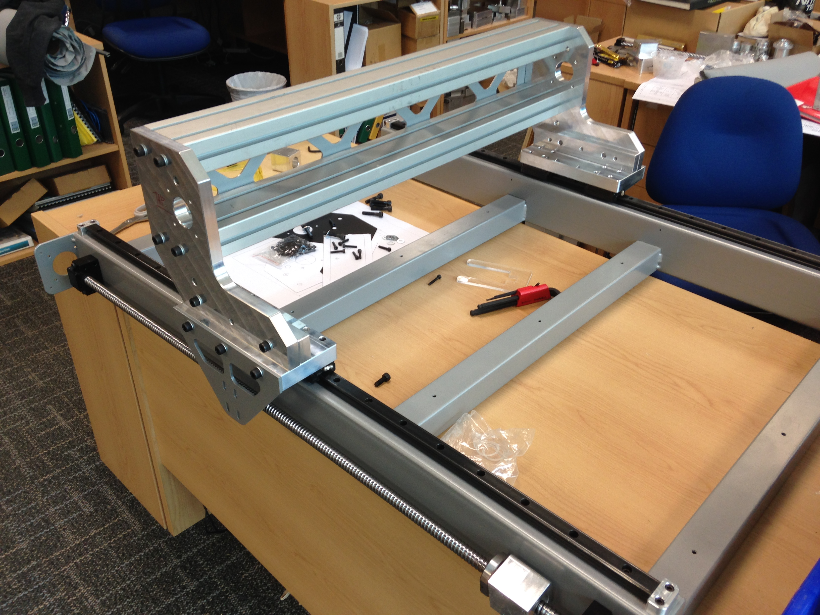
It's 2, 4080's stacked on-top of each other with a gap in-between for the ball-screw. I'm going to then mount the linear rails to the faces and attach the gantry perfectly onto the face of the plate. This design is much more optimal and distributes the load of the z axis more evenly. Another thing I can add later is a plate on the back so that the 4080's act as one and will decrease vibrations and increase rigidity.
I feel like this design will be more rigid and even easier to assemble, and I had concerns about it earlier, but because of the fact that I can upgrade it really easily, makes it definitely worth while to do.
It will be a bit annoying to design though because I've done all of this design work on the current version, but I don't think it will be too complicated. I can kind of move the ball-screw assembly/design just down for that and replace the 8080's with 4080's.
Now after re-orienting everything I have a nice design like this:
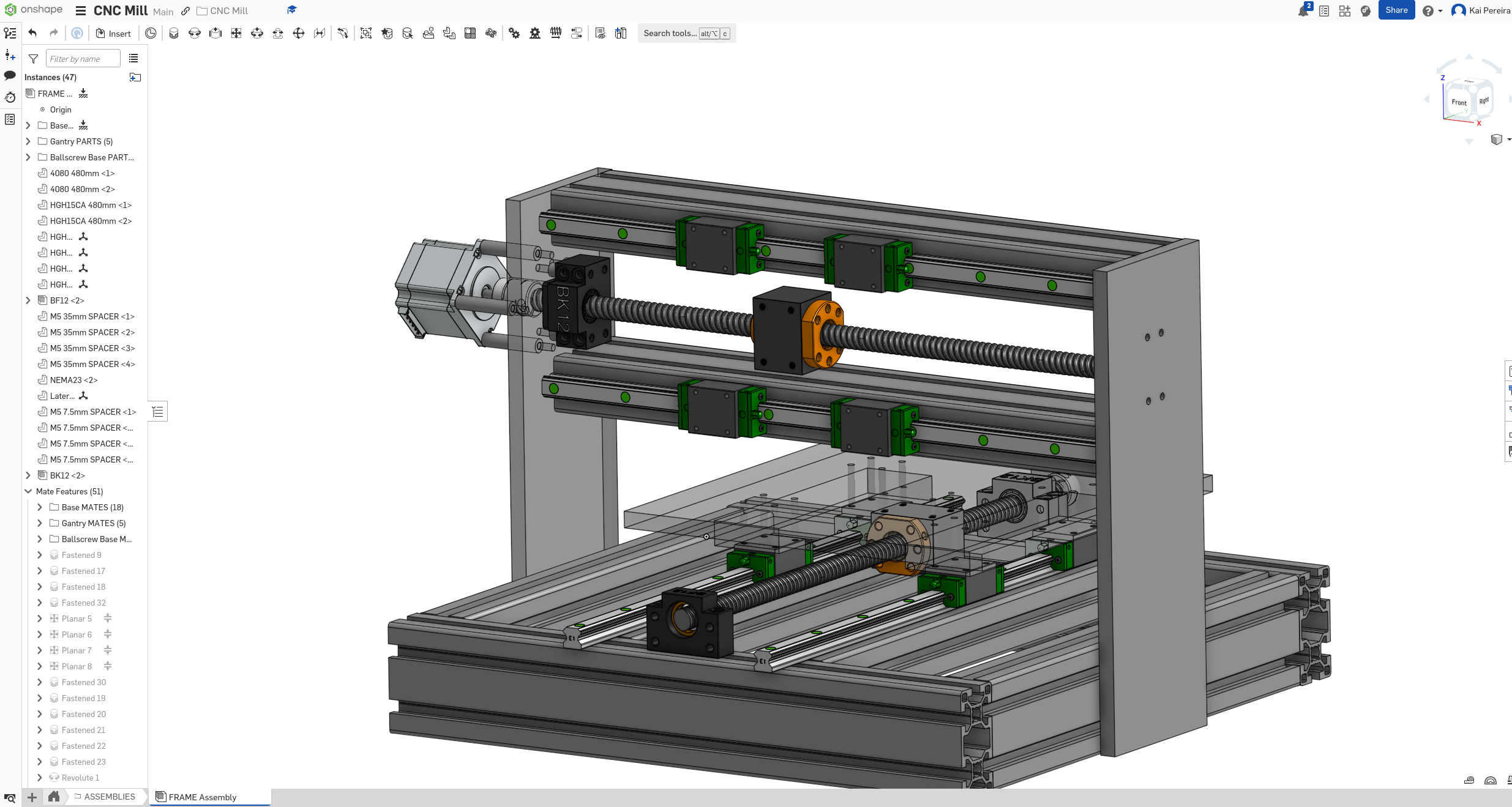
A couple things I didn't specifically mention I did were: - Rotating the BK/BF support, for the rotated ball-screw - Changing which side the BK/BF support are actually facing (forwards with the ball-screw now) - Making the side panels wider and moving the ball-screw to be closer to the linear rails.
And just like that, I have a much more reliable and simple design. There's still a couple of problems with it though: - It's pretty tall from what you could tell, so I need to make it smaller or increase the height of the gantry - The ball-screw and rails aren't flush to each other - The BK support still uses spacers which I feel isn't optimal.
But now that I have the general thing down, I kind of want to revisit the side panels. So currently the side panels are made from 10mm thick aluminum and I kind of just made the dimensions to what I wanted. But to buy metal exactly in that shape just costs way more so I want to use stock metal.
This was the perfect use case of ChatGPT for me and it gave me LOTS of good suggestions:
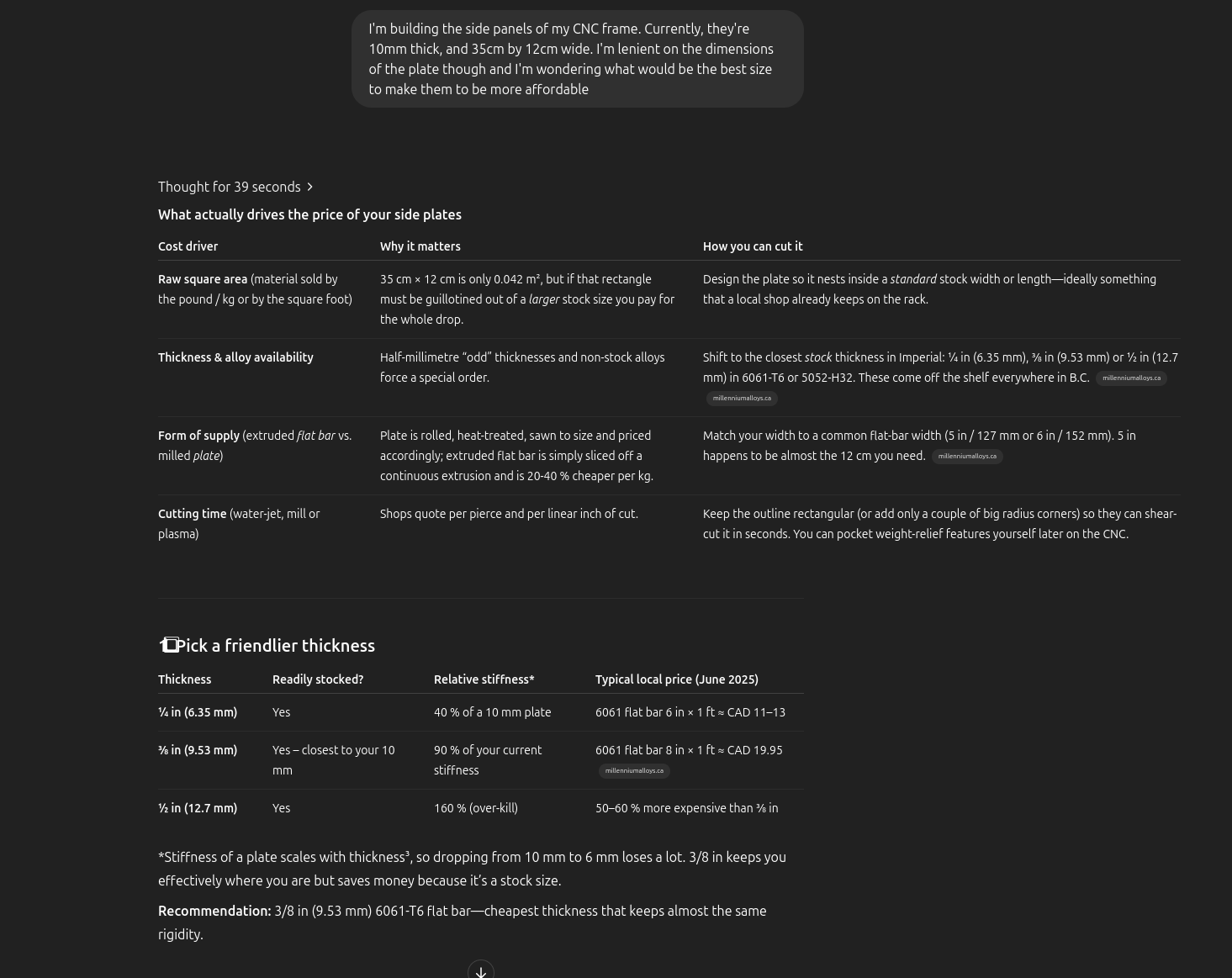
Here's the consensus though:
- Use 3/8 or 1/2 inch aluminum that's already stocked, I'll probably use 3/8 because 1/2 is 50% more expensive at least (3/8 is 9.53mm which is also very close to what I need)
- Use a stock bar dimension like 6061 flat bar 8 in × 1 ft
or something close that doesn't really need to be modified
- Use some supplier tricks to save on costs
So here's the stuff I want to implement based off of this now: - Widen the plate to 125mm so I can use a flat bar and not a milled plate - Increase the height to 14 inches to fit on the saw nicely - Ask the supplier for drop pieces/off cuts
I'll take a look at the bed another time because that's a bit more complicated but let's put these quick changes in!
And just like that, we have our new side panels!

Now check out something neat with our ball-screw now. It's nearly flush with the linear rails:
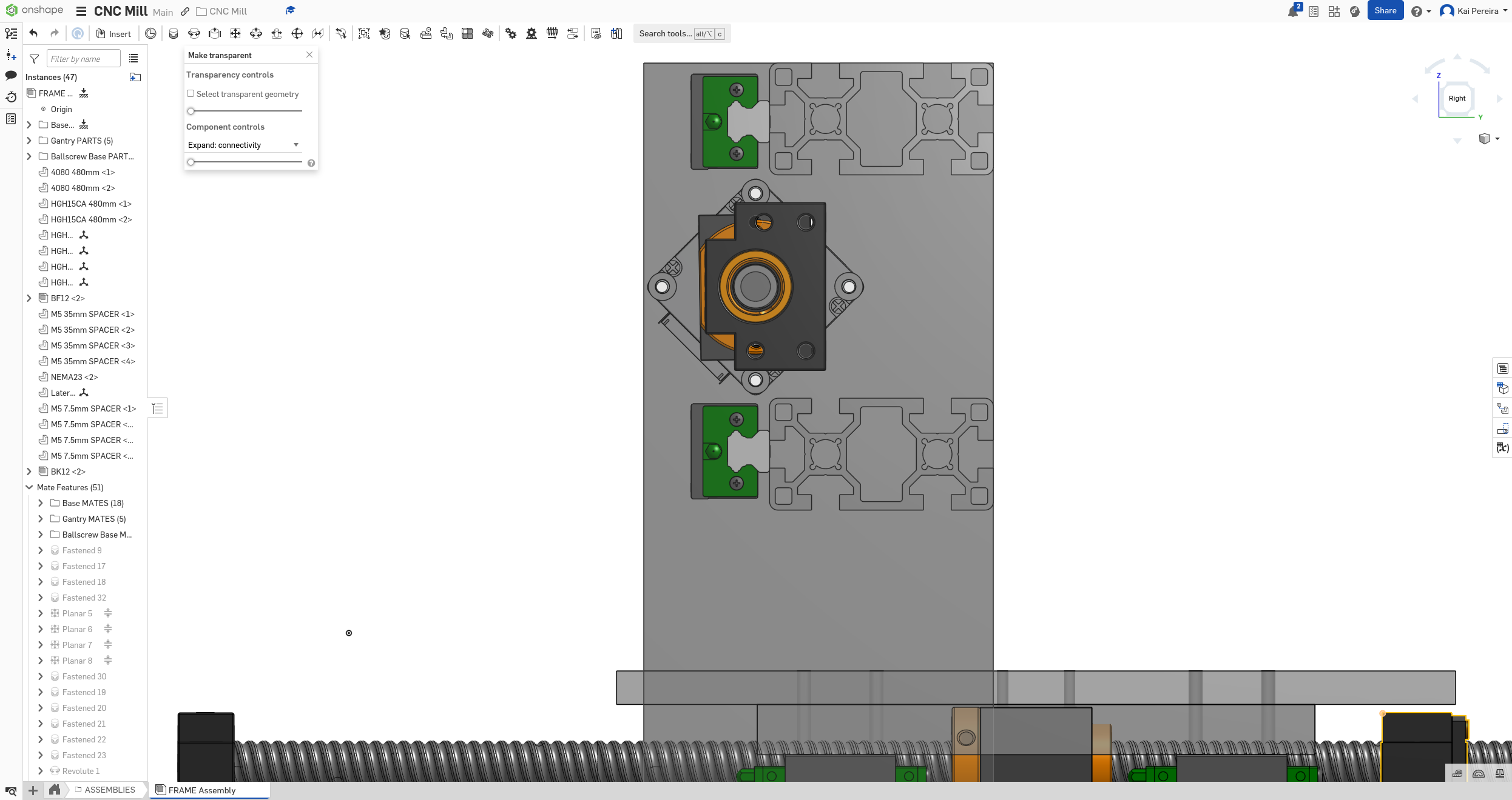
This gives me the opportunity to just use one plate for the gantry which would be really cost effective and handy.
But I'll save working that out for tomorrow. I got lots of good work today done and tomorrow I have a couple of things I want to maybe work on: - Do some more spindle research - Work-out getting the ball-screw flush with the rails - Maybe doing some research into metal suppliers - Start working on the Z-Plate
But anyways, I've been pretty lazy lately so progress have been a bit slow (it's also allergy season so my eyes are really suffering) but still making some steady work on the mill.
Total time: 69 hours
Day 23 - Some more gantry and spindle work
I had a couple of small things I wanted to just get done with today. So let's just get into it!
First I want to get the ball-screw flush with the rails, this just involves either making the plate wider or moving the ball-screw to the side. I think I'll be fine moving it just a tad. HGH rails withs their carriages are 3cm tall, and then add the 8cm of the extrusion -- the face of the ball-screw needs to be 11cm from the edge.
The ball-screw housing has equal sizing on each side, so if we take the center, we can count from the center outwards and have a references point. You can see from the center out, it's 2cm.
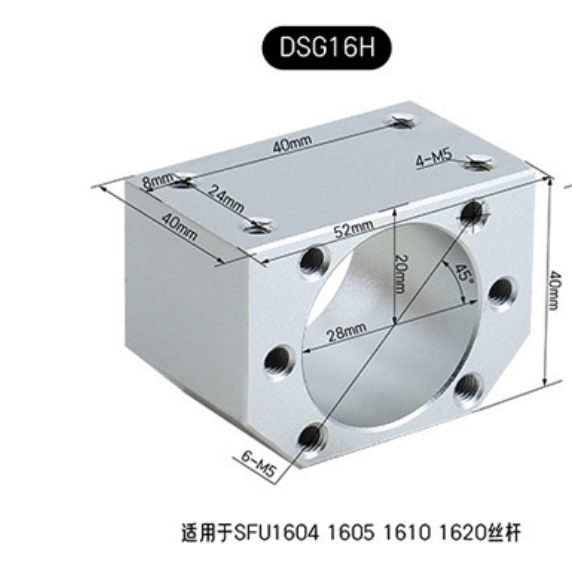
So I drew a little line from where the face of the ball-screw sits:
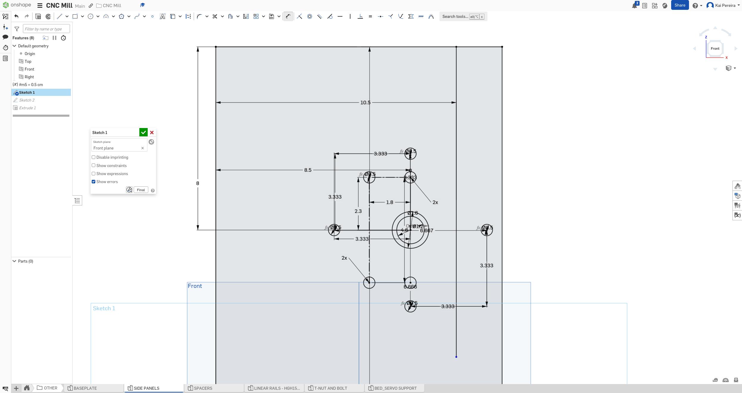
To make it easier to see that I need to add .5cm to the offset. This makes one of my wholes go off though so now we need to fix that!
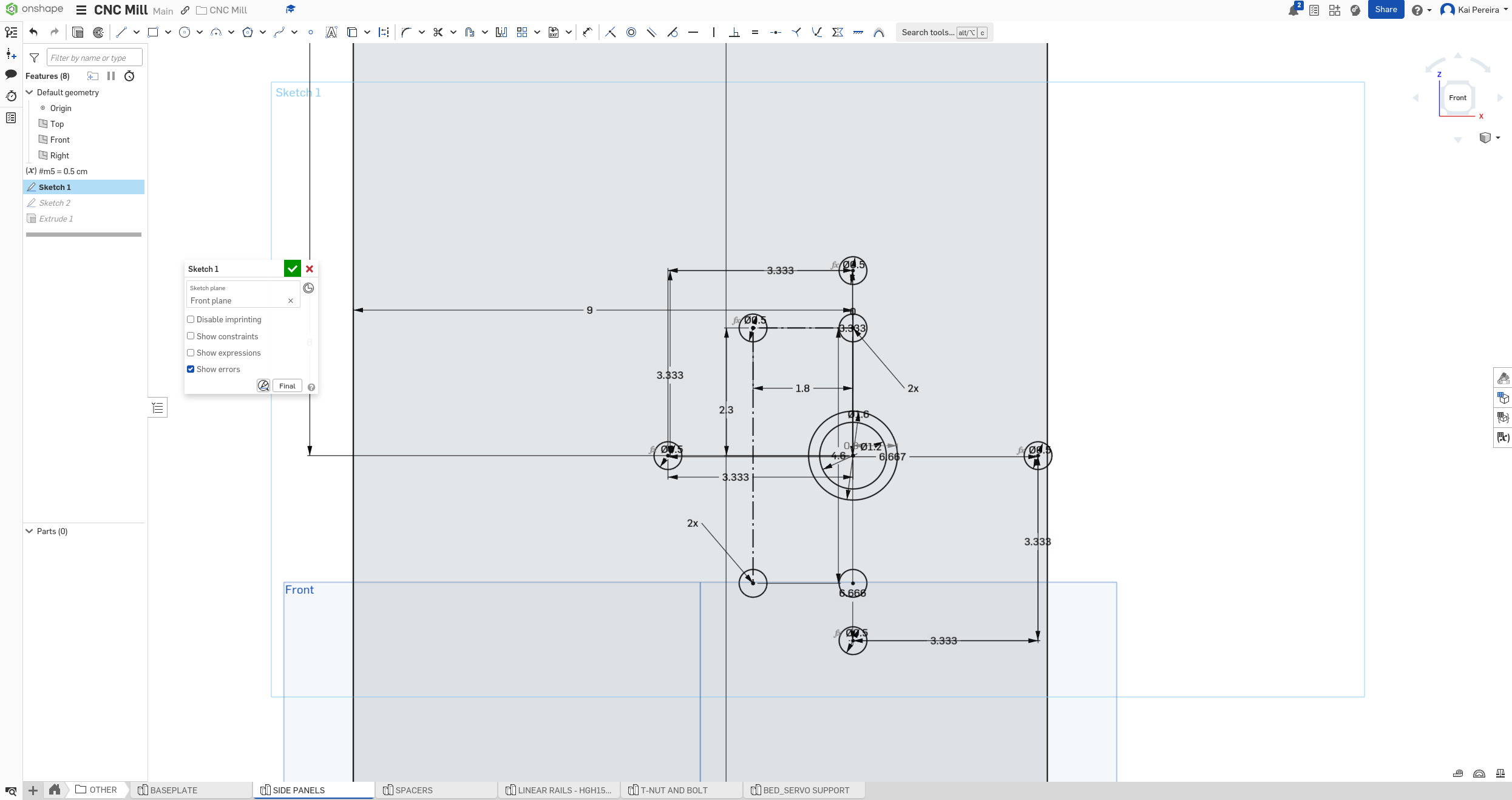
AND they're not aligned and quickly I realized that I used the measurements from the HGH20CA rails instead of the 15CA rails which I'm actually using. So I literally just need to take off 2mm.
And now PERFECTLY, the wholes thing line up, the rails and ball-screw are flush and it doesn't seem like the wholes going over the edge of the side panels is going to be a problem anymore!
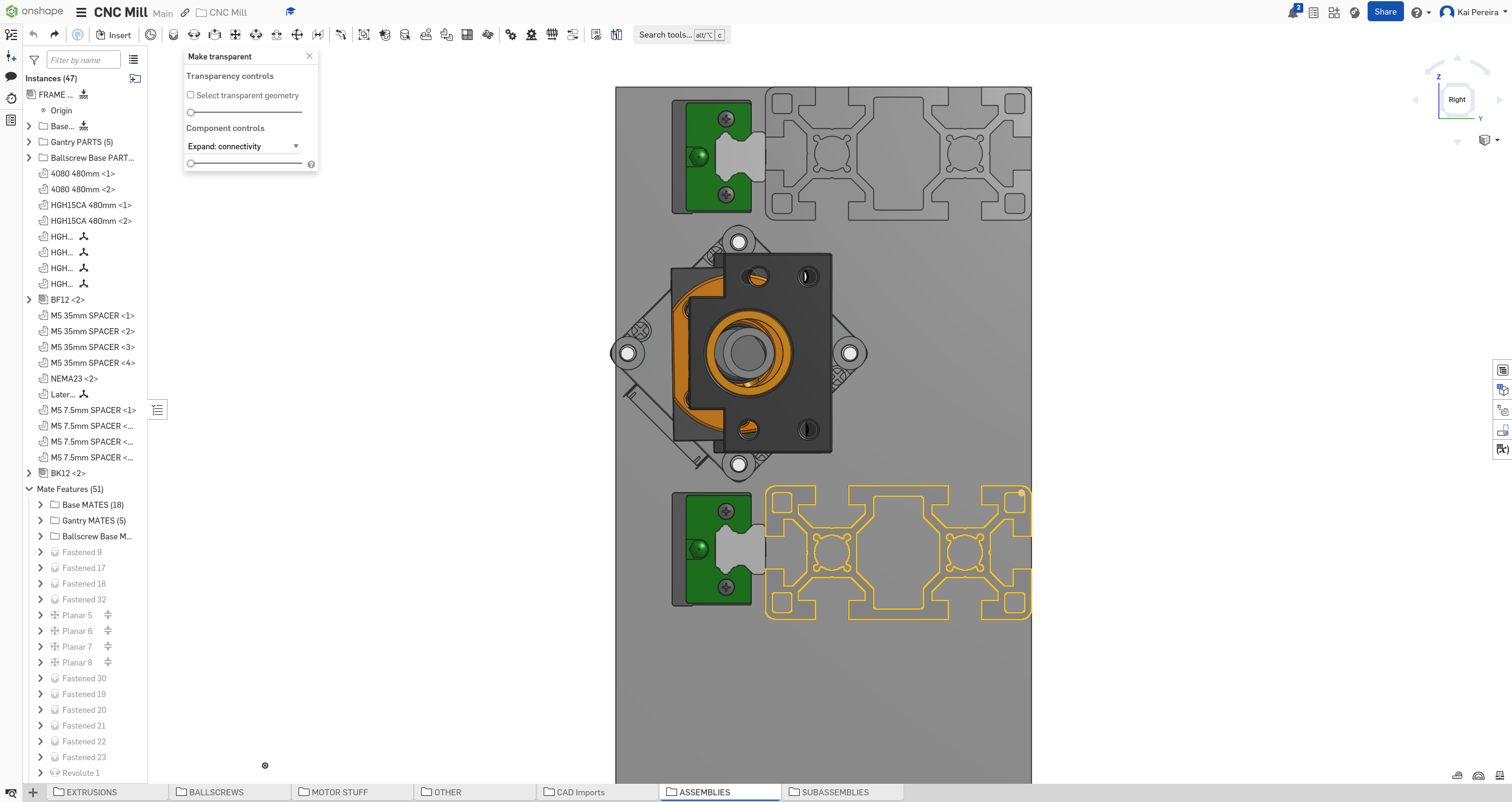
Now let's go back to researching spindles. I know I want to get a 1.5kw air cooled spindle so I should be able to find some actual suitable options. I think I'm going to look more specifically at spindle kits because they're more cost effective.
After a lot of research I've found this beautiful kit on Amazon . I think it's the best price I've found so far, about $160 USD for everything I need with fast and free shipping.
I also found this spindle from Vevor that's probably slightly higher quality but because of the hassle of getting VFD's and collet's, I don't think it's actually going to be easy to use because I don't feel like finding all the extra parts.
So I'm really liking this spindle kit from amazon, maybe I can find a better one on Aliexpress, but I also would prefer buying from China -> Amazon instead of just aliexpress because it's probably a bit more reliable.
Anyways, now that I've found a pretty good spindle, I really want to model it into onshape. I'm going to model this from scratch just so I don't have a very complicated spindle and so I can change it easily.
But as I'm looking at dimensions, I'm still going back and forth between the collet size. I've watched a couple videos though and it should be fine. I can mill light to medium aluminum which is pretty good, and at the end of the day, I can replace the spindle to make it stronger if it's performing well.
Anyways, let's get back to the spindle. These are the specifications from the spindle kit.
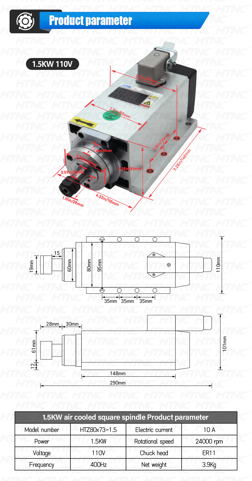 The spindle is an HLTNC spindle, which looks pretty good and I feel like it will be perfect for light aluminum, which I feel like is the standard for my current design.
So using these dimensions I'll create a basic outline.
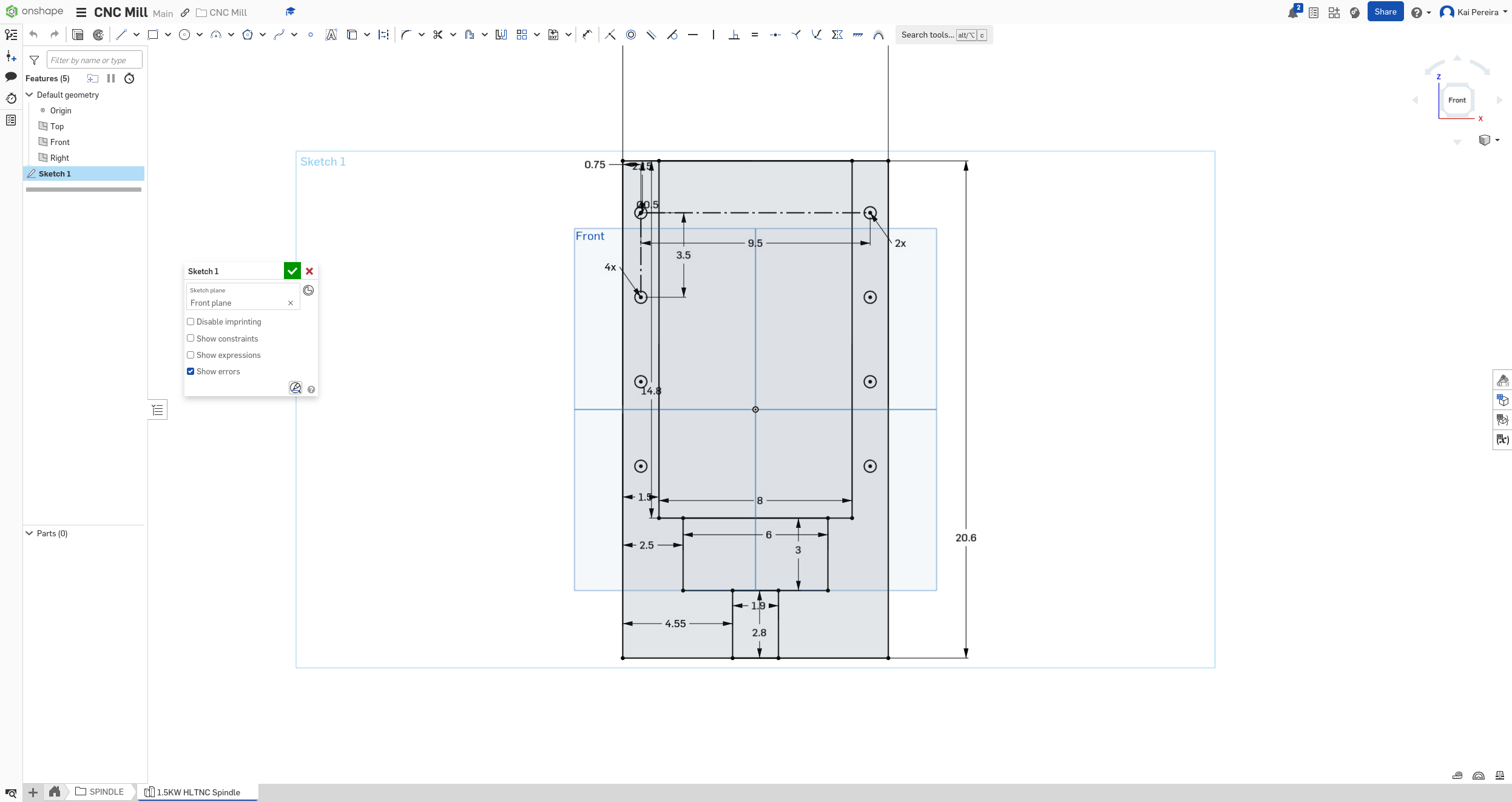
We really just need a general shape for the spindle to represent it's height relative to the bed so that we can kind of visualize how much Z space we have.
Now I'll extrude this using the dimensions to create an accurate depiction. And a little trick is, because the rest of the components are circular, you can just use their dimensions in 3D too!
Then you can offset some of the circular components by taking their diameter and subtracting it from the height and divide by 2 to find the center.
And BOOM, we now have a spindle:
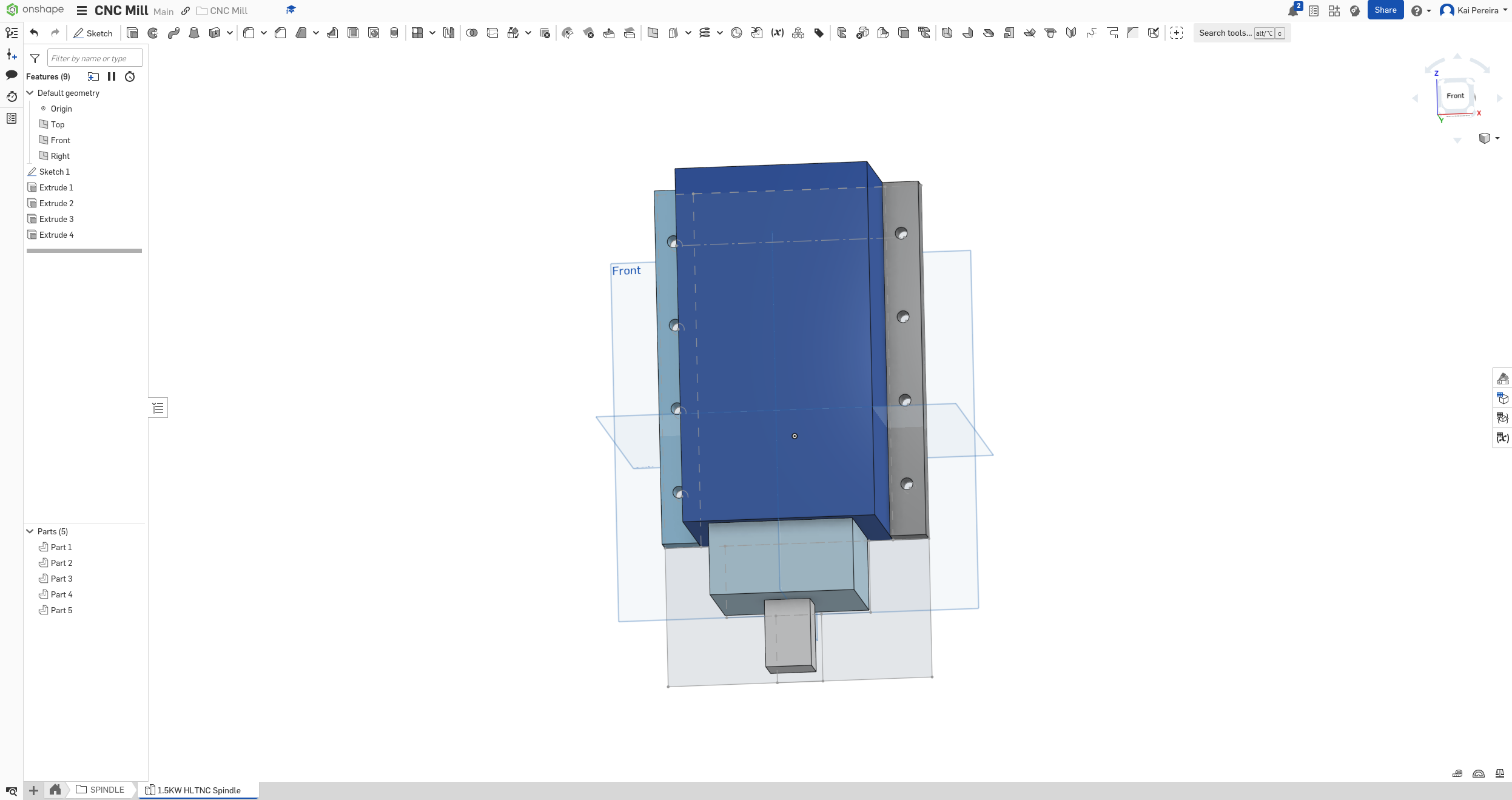
Now we can make it look a bit prettier by rounding and changing the colors. And now it's perfect. I'll just quickly add a boolean to make it all one part and then it'll be perfect!
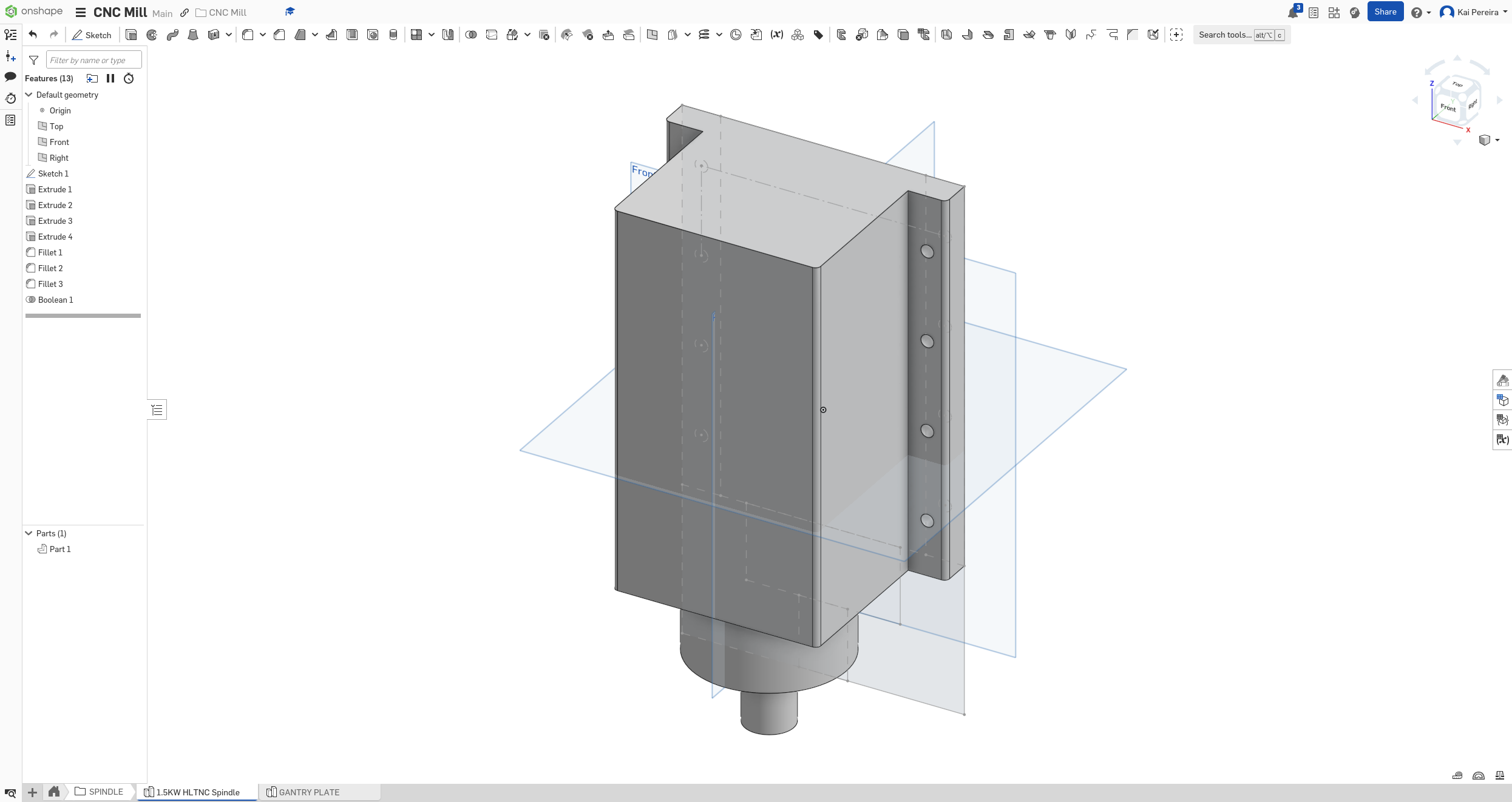
I wish I could have like different colors for a boolean, but that requires having this as like a sub-assembly which I don't really need. Except for if I want to get fancy and simulate like an end-mill on this.
Anyways I'll wrap up my designing for today. It was a pretty productive day I'd say and I got most of the stuff I needed to get done today. I'm giving myself a timeline of 7 days to wrap up this design so that I can order all the parts, so just 7 more days of designing, which I feel like is pretty realistic.
Anyways tomorrow, let's get started on the spindle, that means getting a spindle plate, mounting rails to it, all the fun stuff!
Total time 72 hours
Day 24 - Spindle shenanigans
We're kind of on the second last stretch of building a CNC mill, I just have to add the spindle assembly, and then do the finishing touches. Now the spindle is a bit tricky but I have a good idea of how I'm going to do it.
First I'm going to have a plate that's mounted to the rails/ball-screw. This plate will have rails and a NEMA 23 at the top to drive it's ball-screw. Then those rails, will have another plate, of which the spindle will be attached too. Simple enough, I'm just not sure how I'm going to bolt it all together. But anyways I think that's more of a problem once I have the first plate implemented, so let's get started!
First I want to do some calculations so that I get the rails and ball-screw all perfectly attached to the plate. This is just some quick math that I did based off the rail and ball-screw dimensions:

I'm not quite sure what size to make the X and Y but honestly, those don't really matter for now, I just need to get the relative dimensions of the holes in.
So now let's design this plate, I'm going to put all of this stuff inside of a spindle folder just for ease of organization, and just like that, we have our plate. There were a couple dimensions that were off for some reason, but with a bit of modification, I got it in.
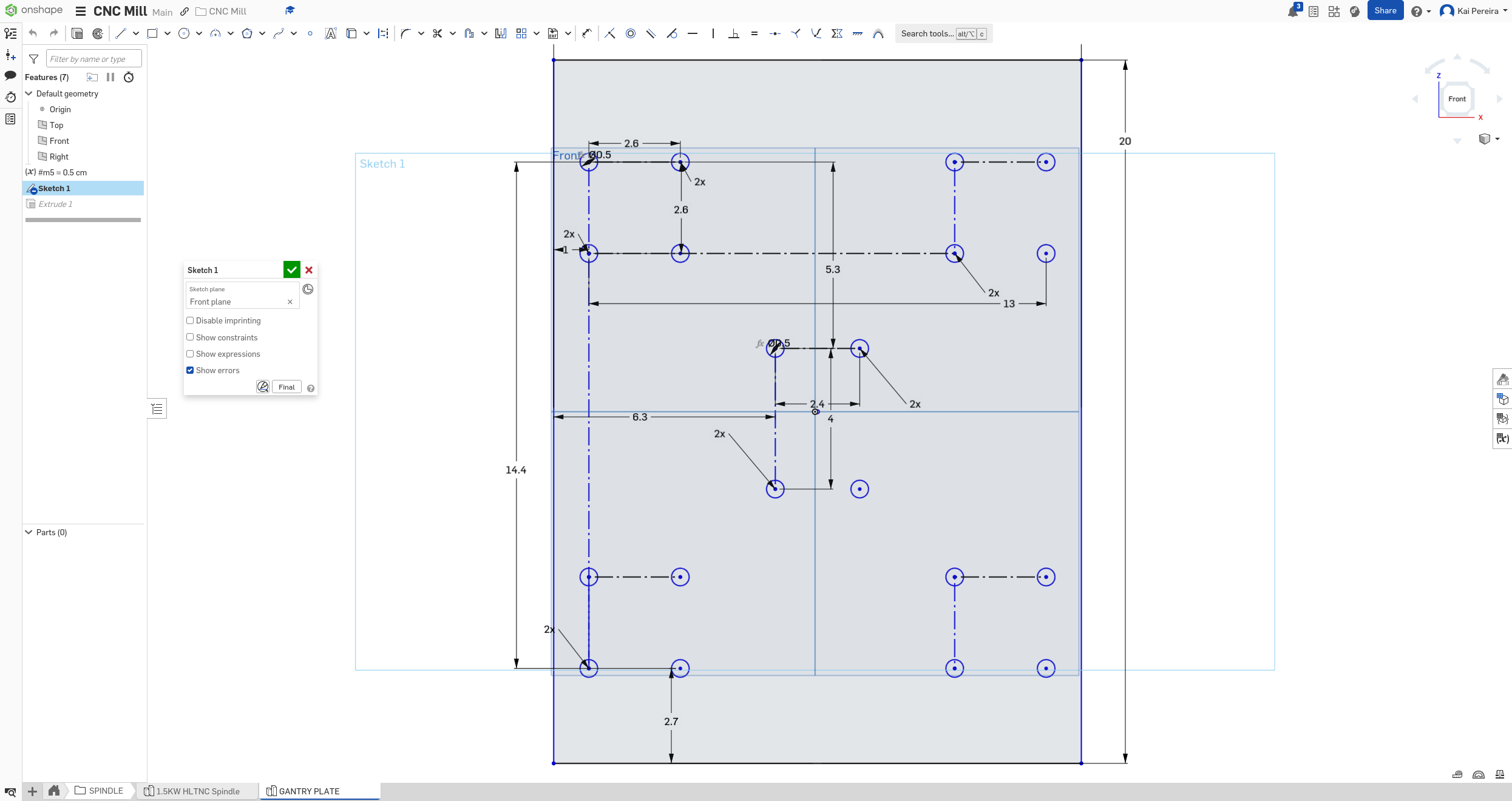
Now we can just extrude this to form a plate. I'm going to choose 3/8" aluminum, so I'm going to make the width 9.525mm.
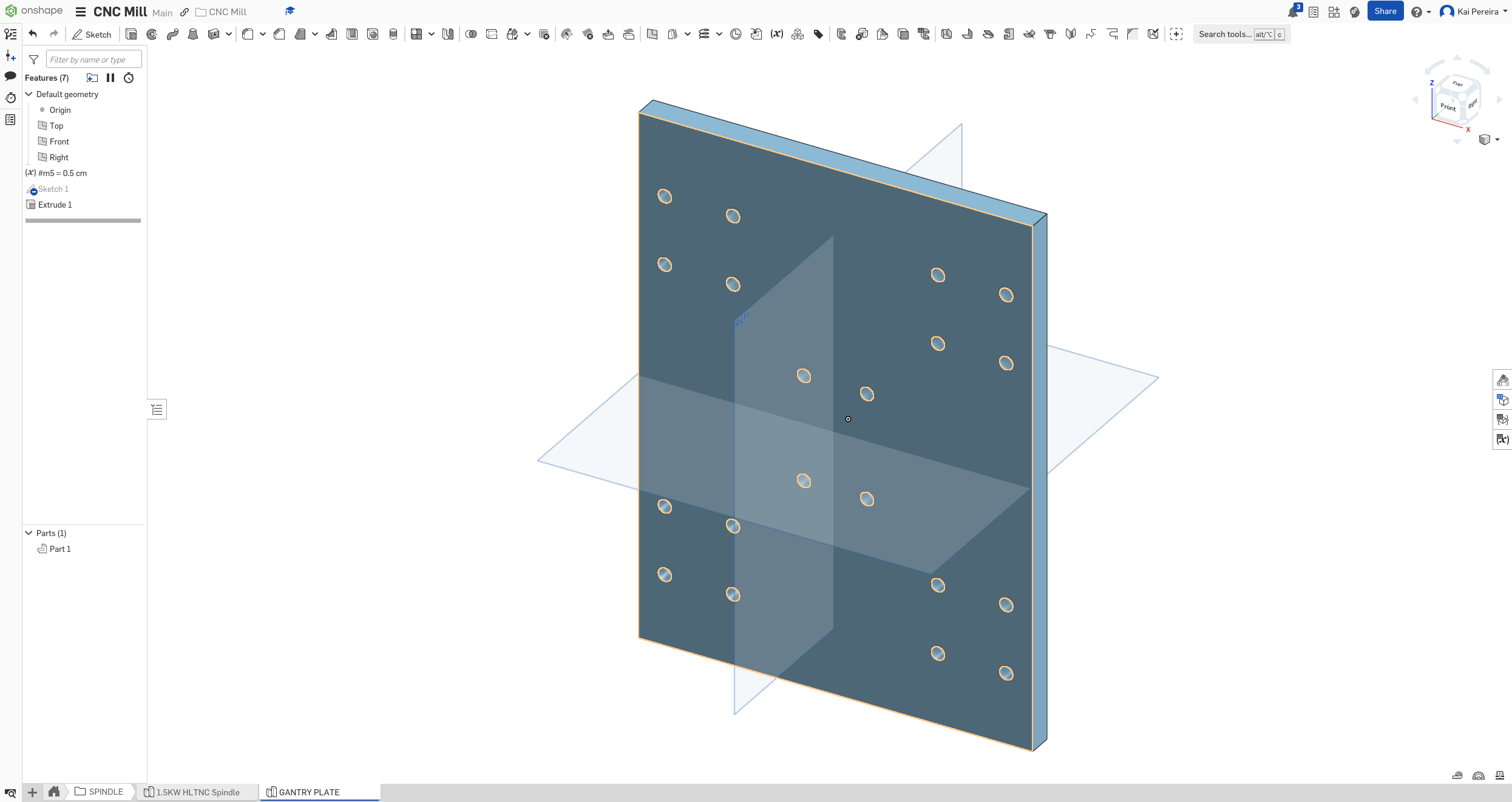
Now I'm not going to really worry about the dimensions for now, I'll just make all the holes and stuff relative to each other so I can dynamically change the width and height.
Now let's put this in our assembly just to see how it fits, and perfect!
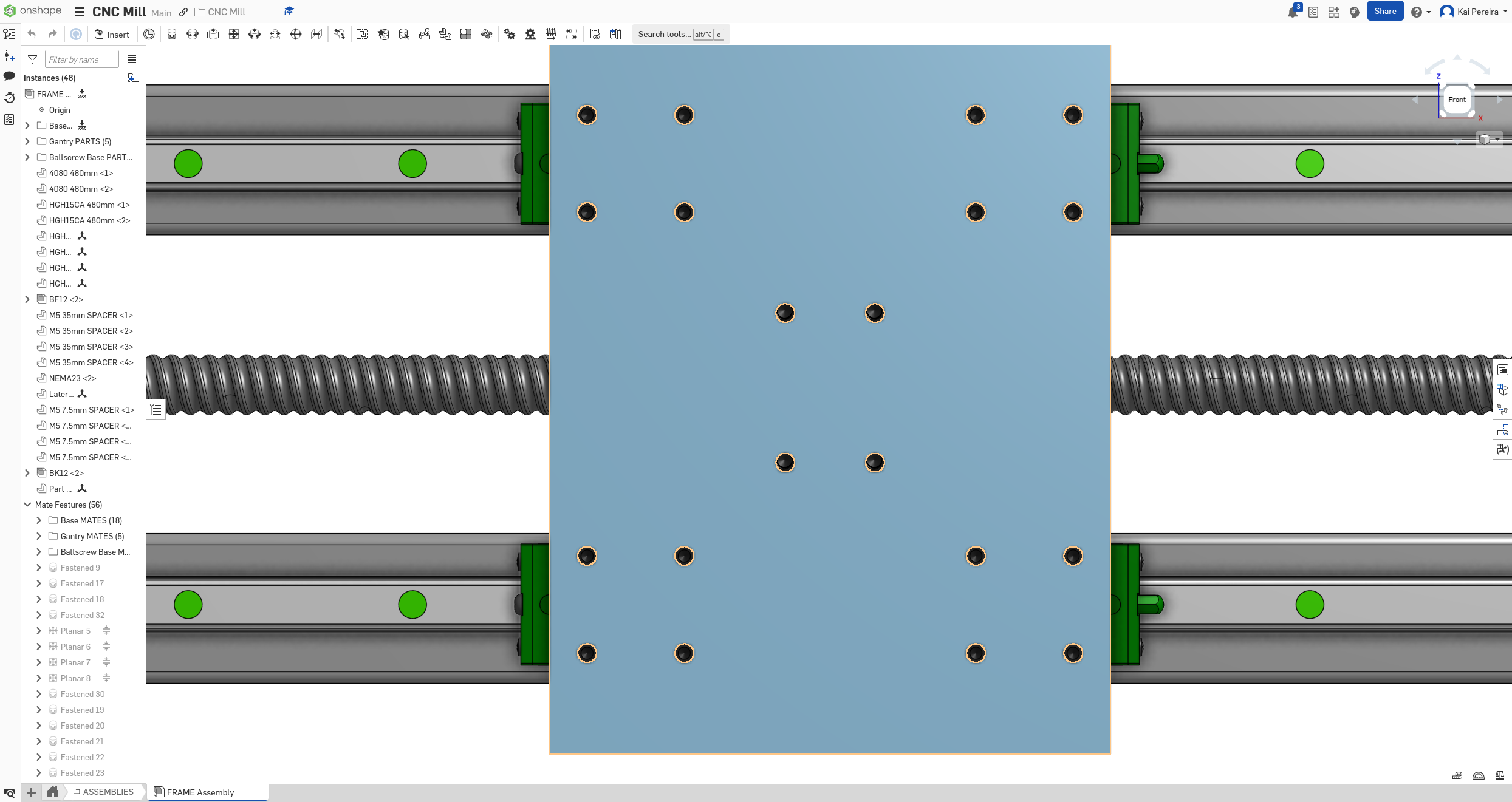
The ball-screw is at a slight angle, I'm not too sure how to actually fix that, so the holes might be just barely off. I usually just group the ball-screw with the plate instead of fixing it because it breaks my whole assembly when I fasten it to the plate. Probably because it's at an angle, but I'm really not too sure.
Let's just change the color real quick and boom, the spindle assembly, already looks pretty good!
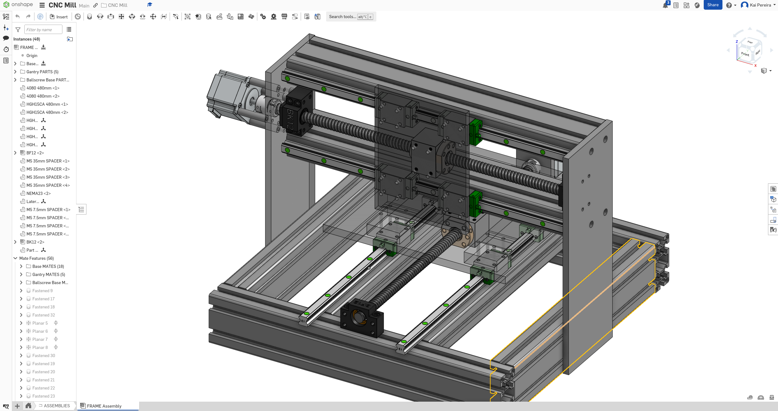
Now I'm going to add some rails to the plate. I chucked a rail onto the plate to just see if I could nicely space a rail between the carriages and it actually works out perfectly!
The holes on the rails are 4.5mm wide and they're spaced out 60mm. I want the rails to be closer to the center of mass too so that the spindle gets less vibrations and has more stability. With this in mind, let's put the holes on.
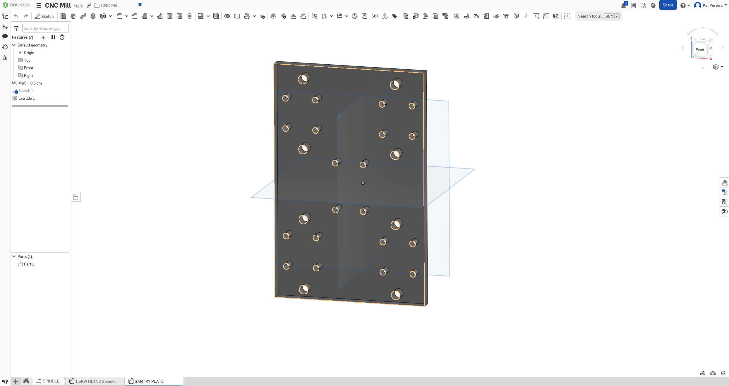
You can see that they fit literally perfectly! Now we're just going to add the rails onto them. For now, I'm just going to make the rails 250mm long because that's a big bigger than the size of the plate. I also decreased the size of the plate so that there's a bit more rigidity and less wasted space.
And that looks perfect!
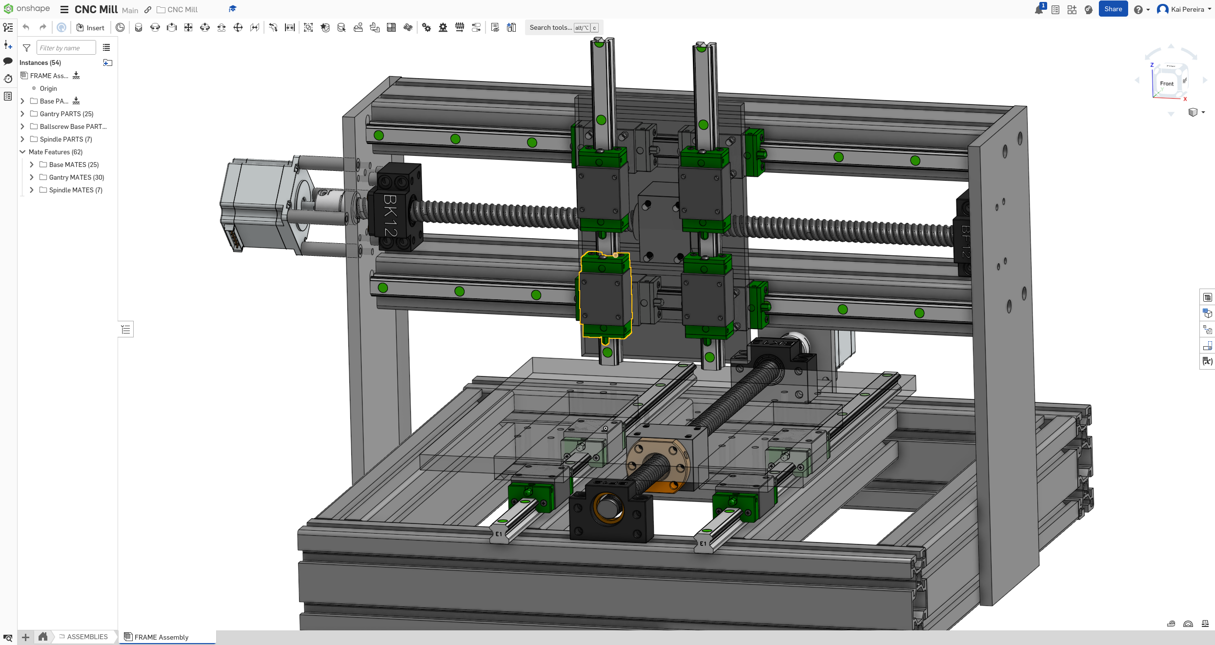
Now I just need to create a mounting plate for the spindle so I can put it onto the rails, I'll just make this plate 3/8" again so that there's not too many vibrations. I want all of these components to be tight nit so it's rigid and there's not too many vibrations.
But before I do that, I just remembered that I still need the ball-screw on this axis. So let's focus on that first. Luckily, I'm using an SFU1204 ball-screw for the gantry because it has a higher mechanical advantage and it's also smaller. So it should actually fit pretty nicely onto the gantry plate.
Before I do everything though, I'm going to put some holes onto the gantry plate will the BF/BK support will lay.
The BF support is pretty simple to model, it's just 2 holes so I'll put that at the very bottom of the plate. But a bit of a problem comes up when I put the BF support on, it intersects with the ball-screw. Now this might actually act as a natural stopper so once I add the full ball-screw assembly, I'll take a look at it. It's pretty easy to increase the distance between rails.
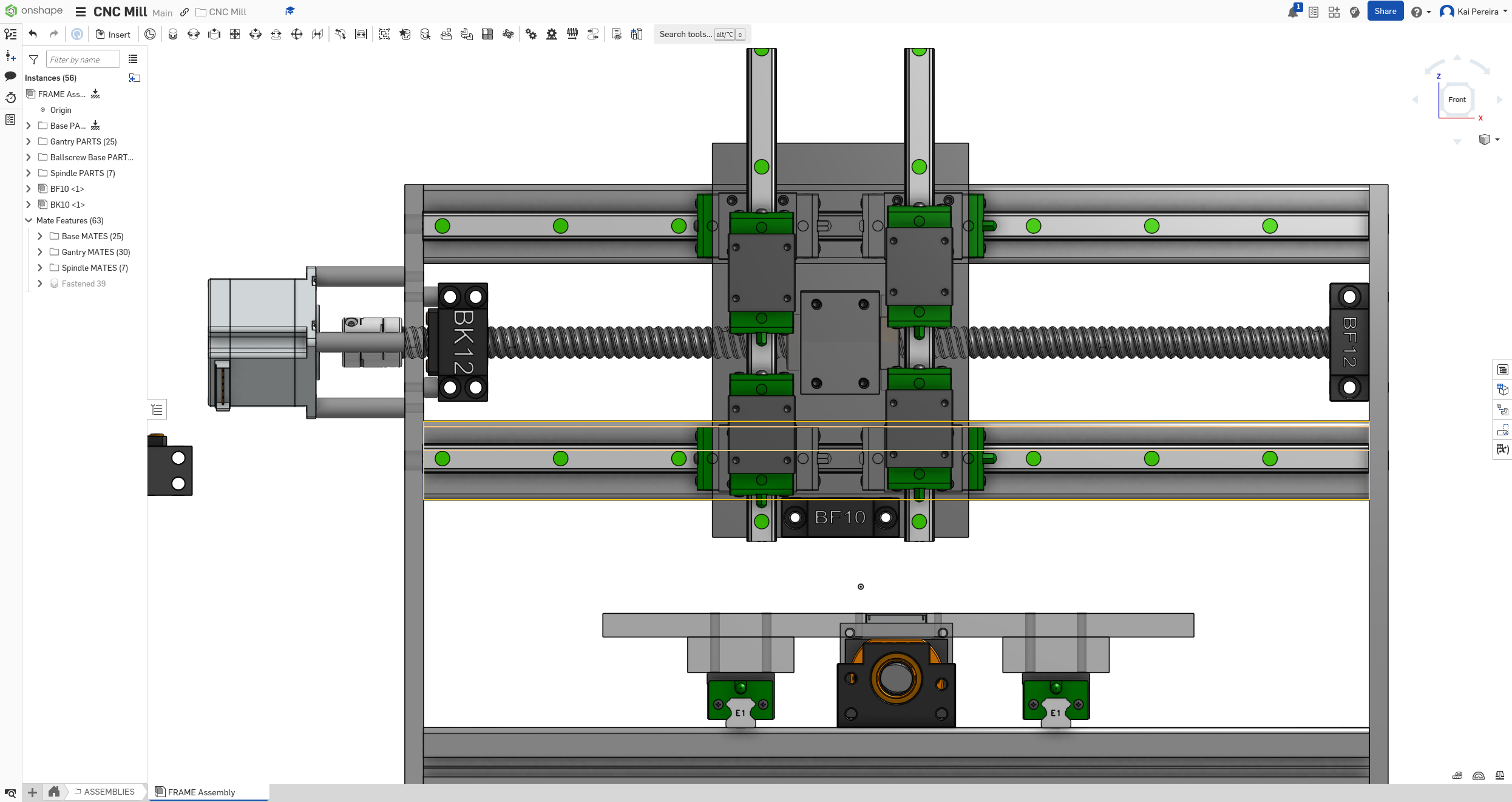
But the distance between it and the bottom looks pretty perfect! Now I'm going to model the BK support onto the plate. It's getting very cramped on the gantry plate, so I might need to make it larger.
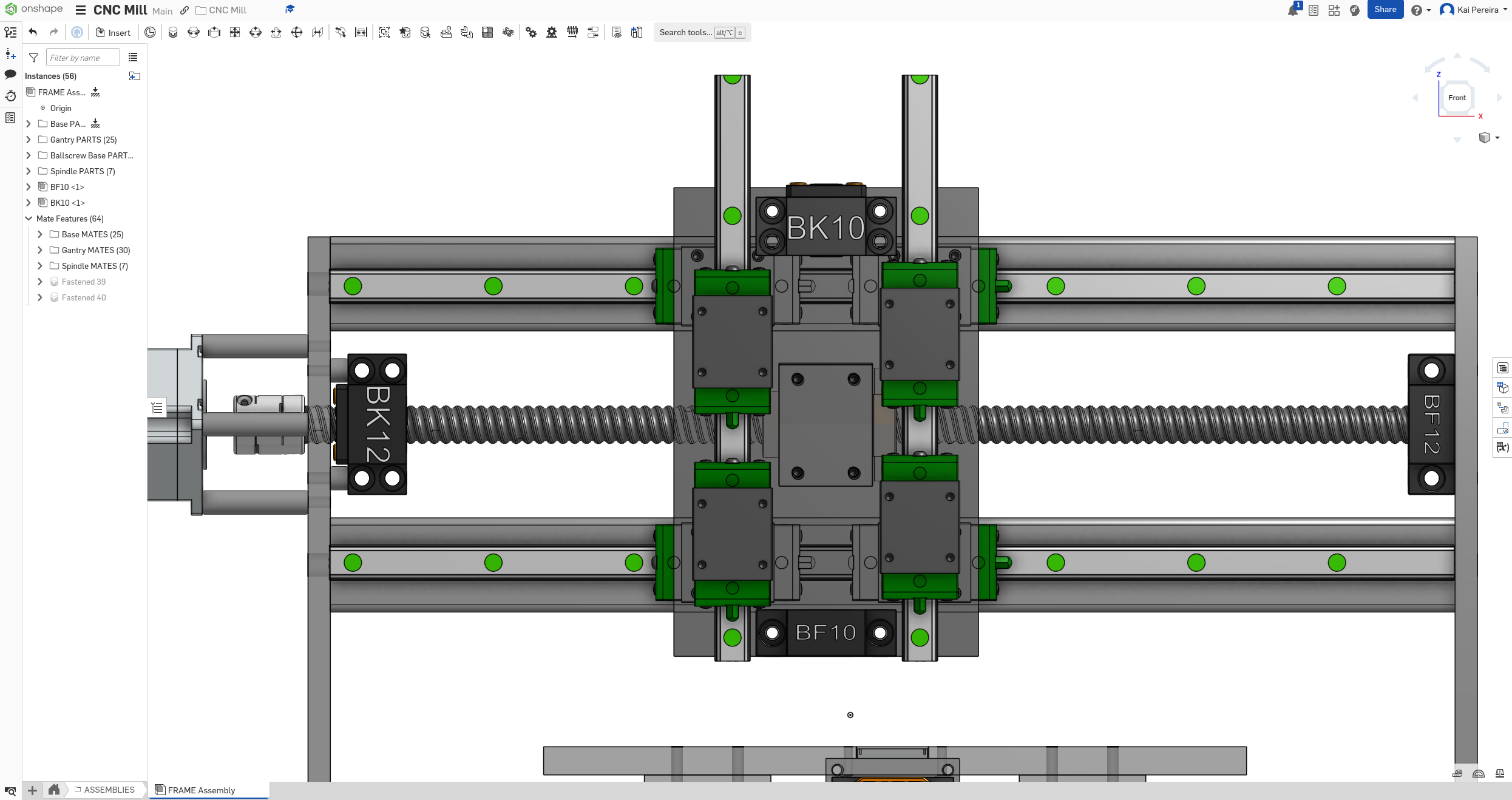
Now you can tell the BK10 support intersects the carriages on the gantry so I'm going to make the gantry plate much larger. I also want enough space to actually put the stepper on the gantry plate but the stepper can be hanging off the top a little so I don't need to make it that much taller.
But anyways it's getting a bit late so I'm just going to end it off here. I did some good work on the spindle but there's definitely quite a few problems with it still.
Tomorrow I feel like I'll be able to finish the ball-screw assembly, and then I'll be able to put on the spindle plate and attach the spindle, and then maybe the spindle will be done. We'll see though!
Total time: 74 hours
Day 25 - Wrapping up the spindle
Alright today I had a pretty straightforward goal, just be able to wrap up the spindle or maybe get it as far along as possible. So let's get into it!
First I'm going to finish that ball-screw assembly I was working on. I want about 150mm of Z travel, this ensures that I have pretty good rigidity on the gantry, but that I can also mill nicely sized parts. I can also pretty easily adjust this in the future, but I think 150mm is a pretty good starting point.
Having 150mm of Z travel doesn't mean that the ball-screw is going to be 150mm long, I need to account for the nut and end supports.
Doing some quick math (24mm (nut) + 29mm (BK support) + 20mm (BF support) + 30mm (coupler)) I need the ball-screw to be at least 250mm long. Because I want a bit of room for error, I'm just going to go for a 250mm screw for now. This might be a bit short, but if it's like 145mm of z travel, I'm perfectly fine with it too, it really just increases rigidity which I think is pretty important.
Now that I have the housing and screw on, you can see that I clearly need to widen the spacing between the rails so I'll do that real quick.
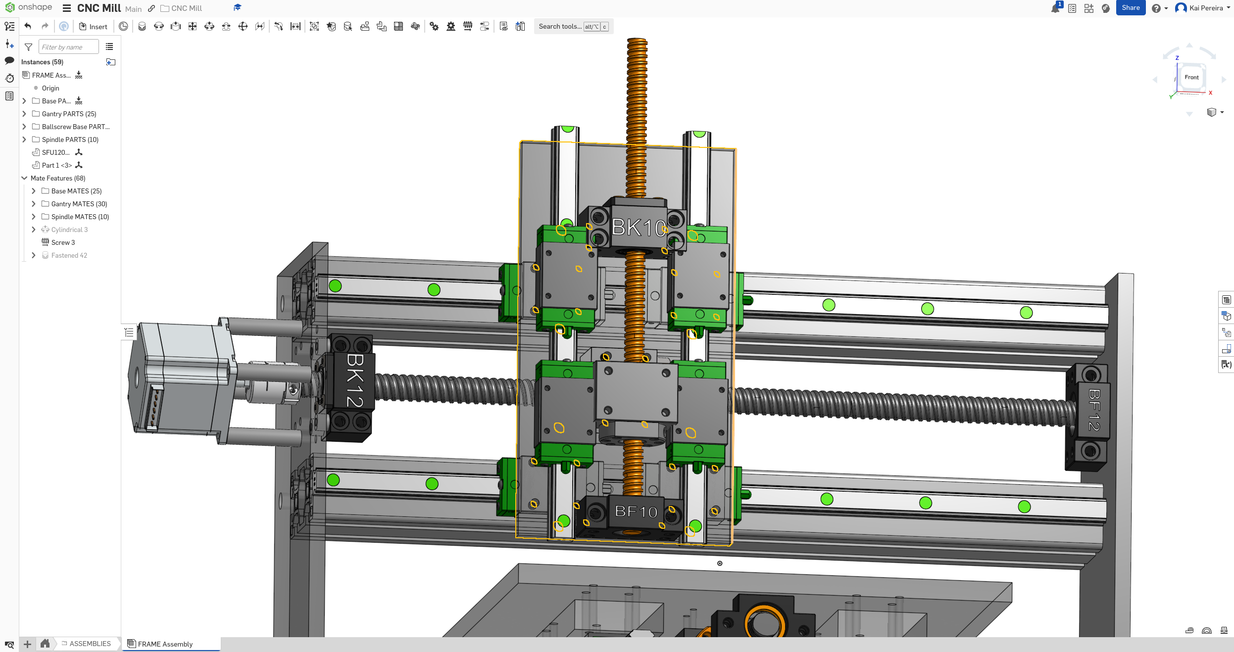
Also for some reason, shortening the screw is being a bit finniquy, so that's a 300mm screw in the photo. I've widened the spacing between the rails by 2cm and it's perfect now:
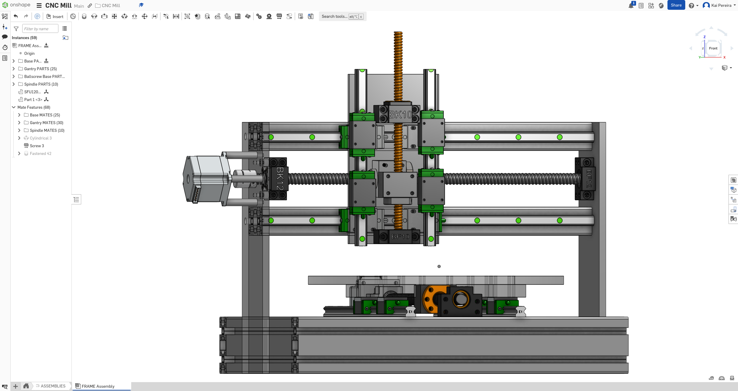
While having the ball-screw in place, I took the change to check out the distance between the face of the carriage and ball-screw and there's quite a bit, so we'll have to figure out how to get the spindle plate on later. I'm thinking same style as the bed and just do a smaller plate on the rails and larger on-top of that.
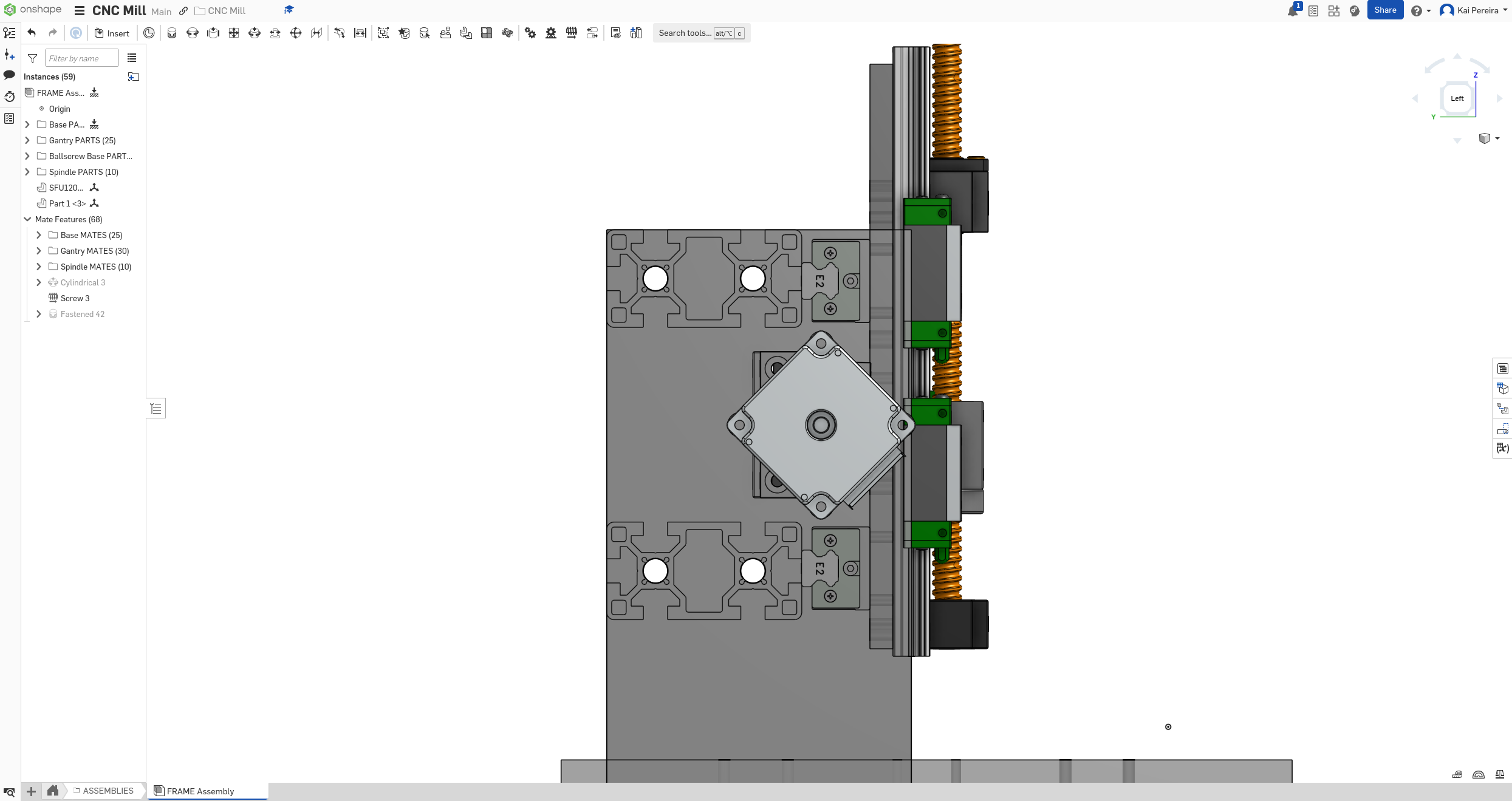
When I was designing though I found that one of my ball-screws was off for some reason. and in a very weird way too.
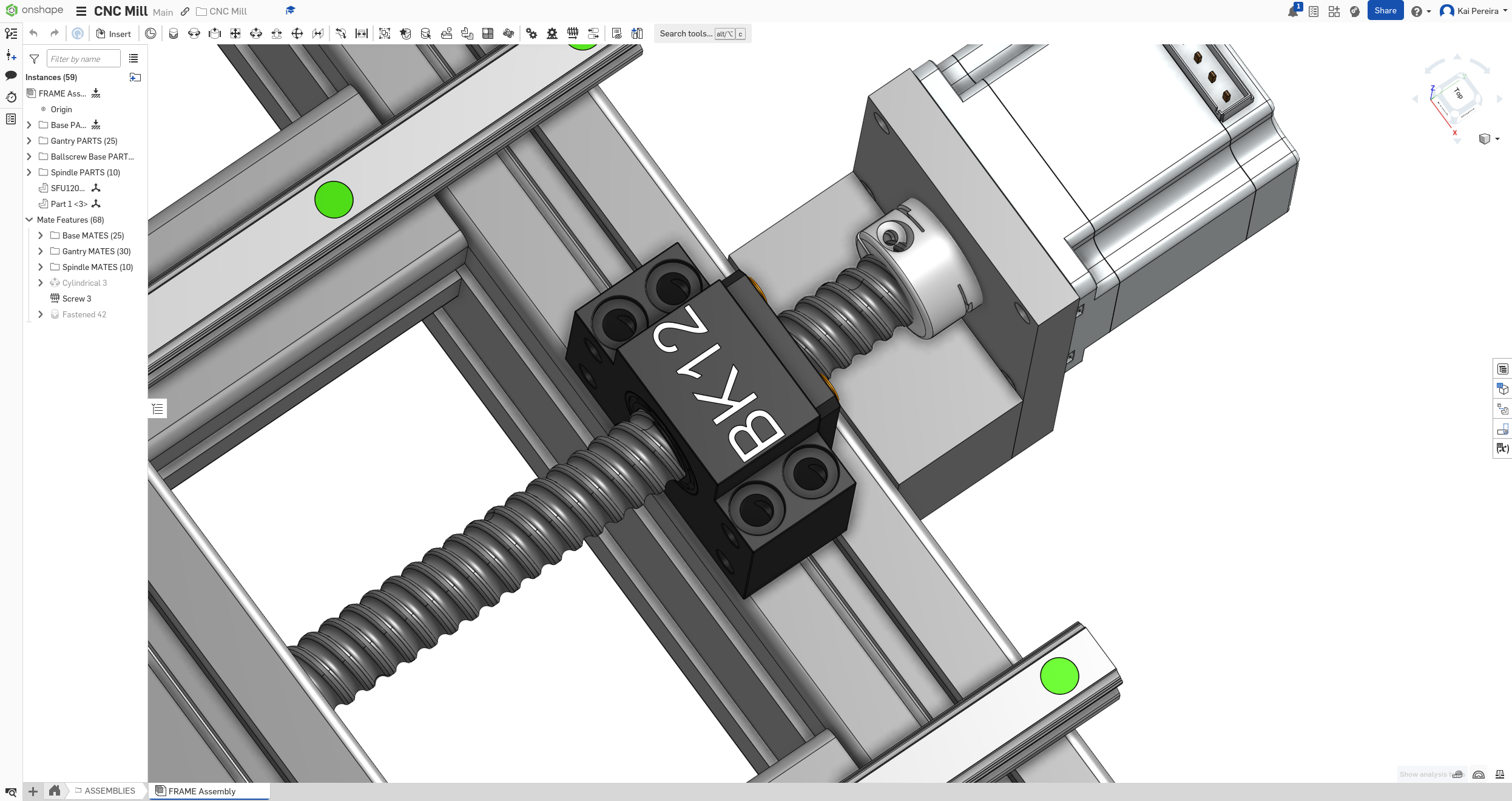
It's a pretty quick fix though, I was using the same ball-screw for the gantry and bed but ones 500mm and the other is 480mm, and I made the 480mm longer for some reason.
Now it's sitting properly and we can get back to the spindle.
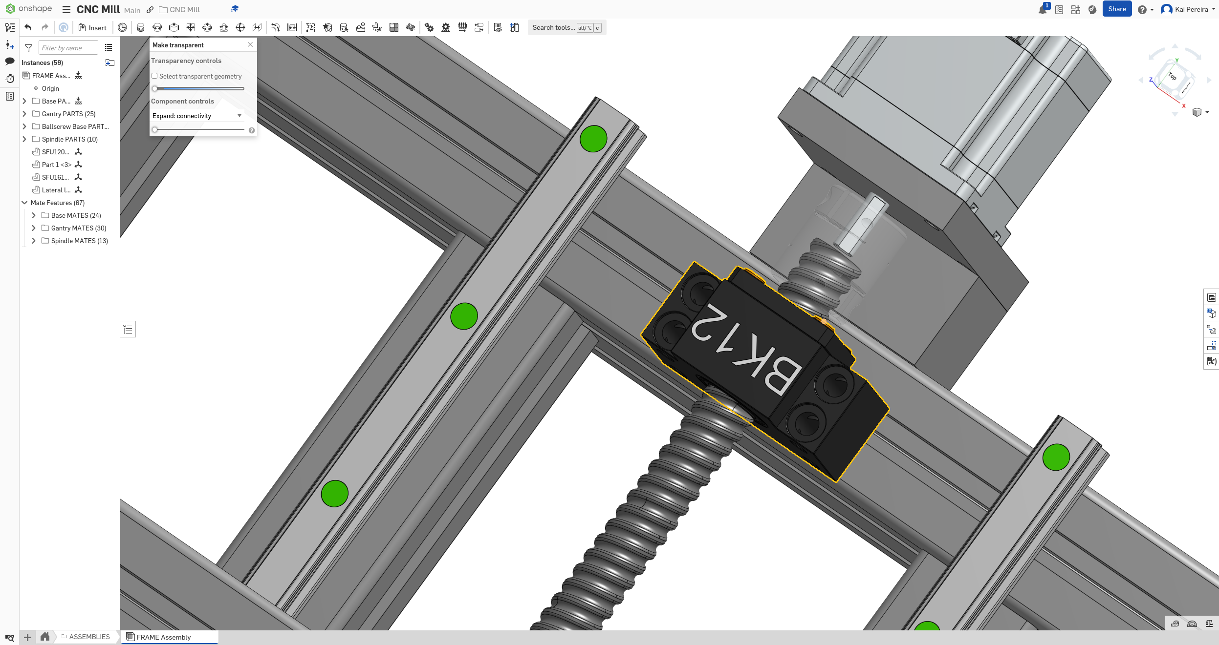
I also really want to design my own ball-screws now because I'm not too sure what the exact dimensions of the ball-screw machined ends are which are pretty important for aligning in the support properly.
So let's get to designing some custom ball-screws. Honestly, I can just represent the ball-screw as different diameter screws. First I researched how big the machined ends of the ball-screws are and found that there's a pretty common standard.
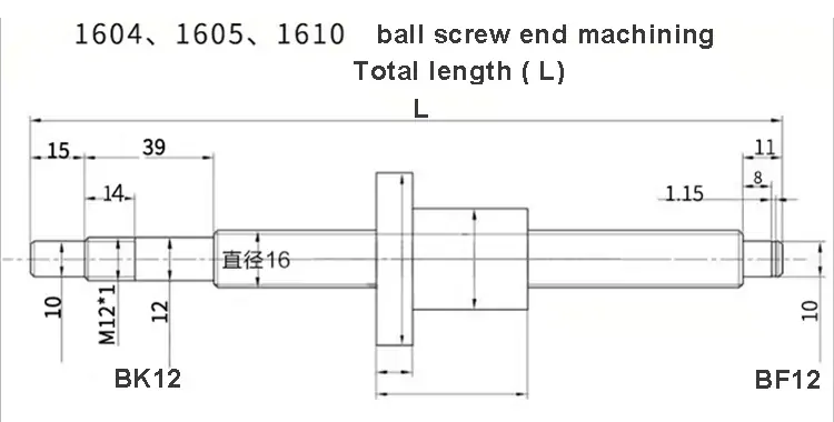
I'll keep the nut because it's a very accurate model but I'll just design new screws. They were really easy to design and then I just put a helix on in case in the future I wanted to make them actual screws.
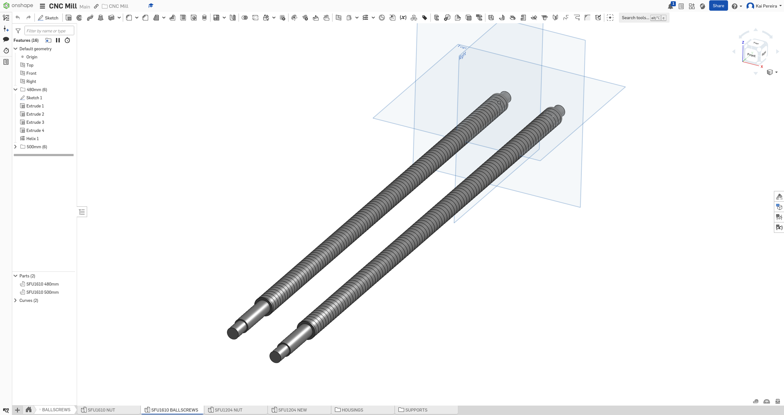
I then did this for the SFU1204 which had slightly different dimensions.
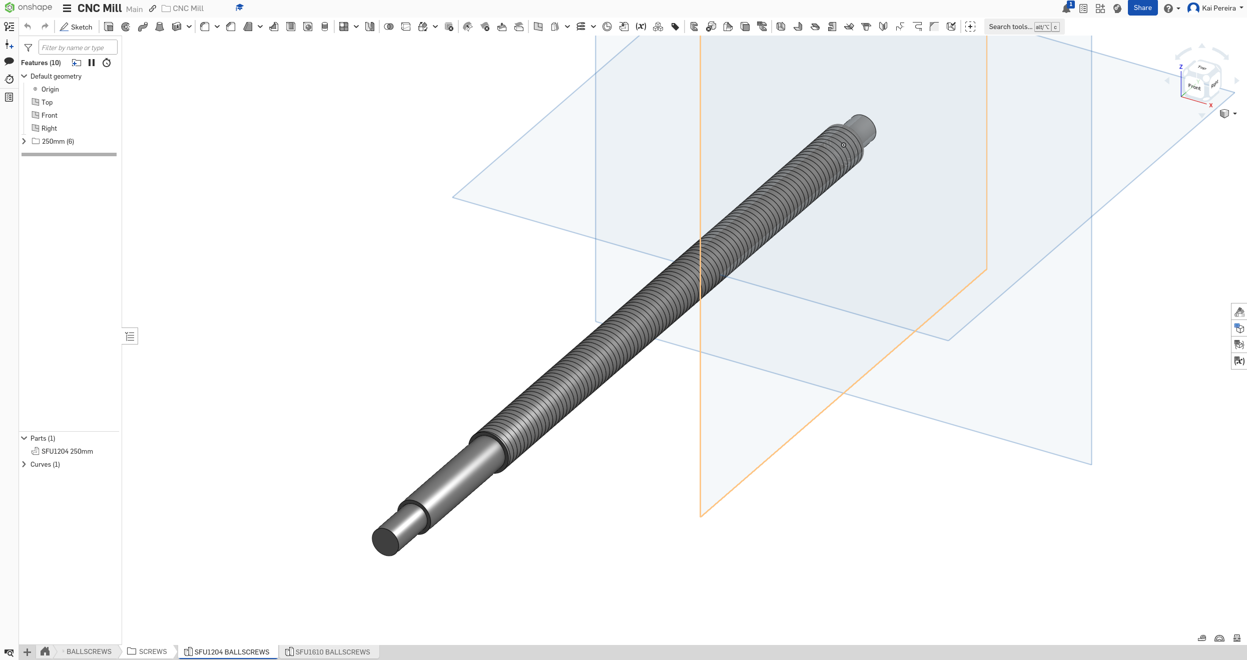
Now I have to do the slightly monotonous job of putting this into the assembly because everything is broken now. But anyways a bit later, the assembly is perfect.
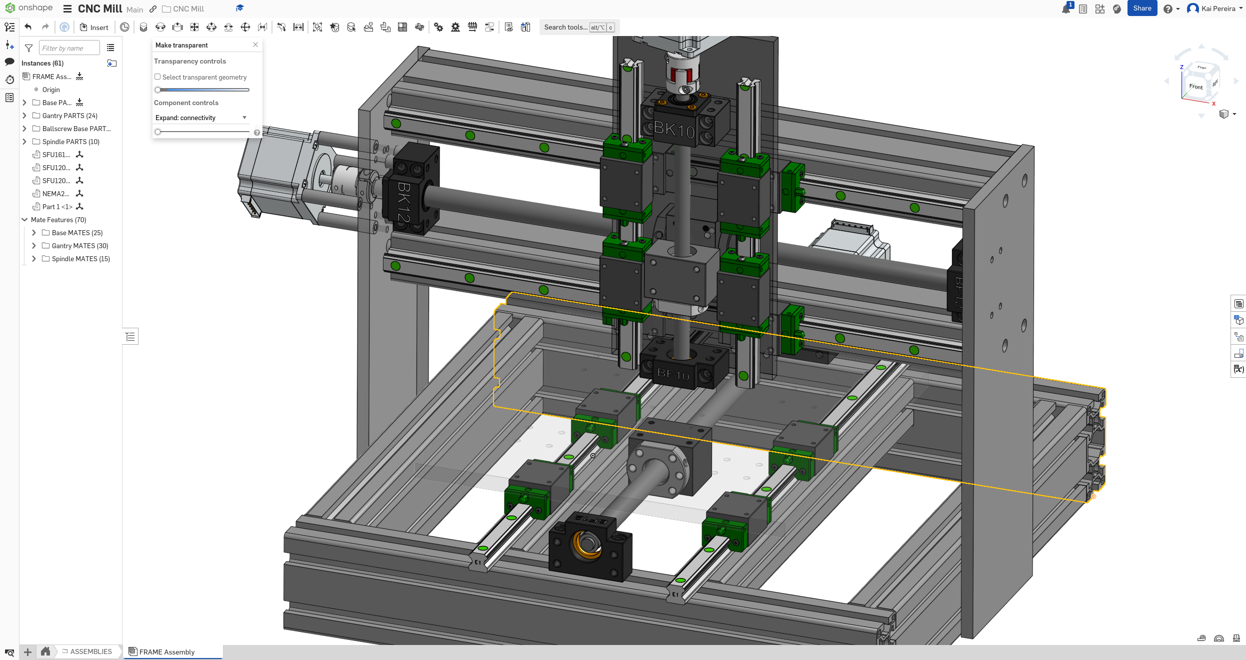
Now I can verify that all my ball-screws perfectly align with the supports.
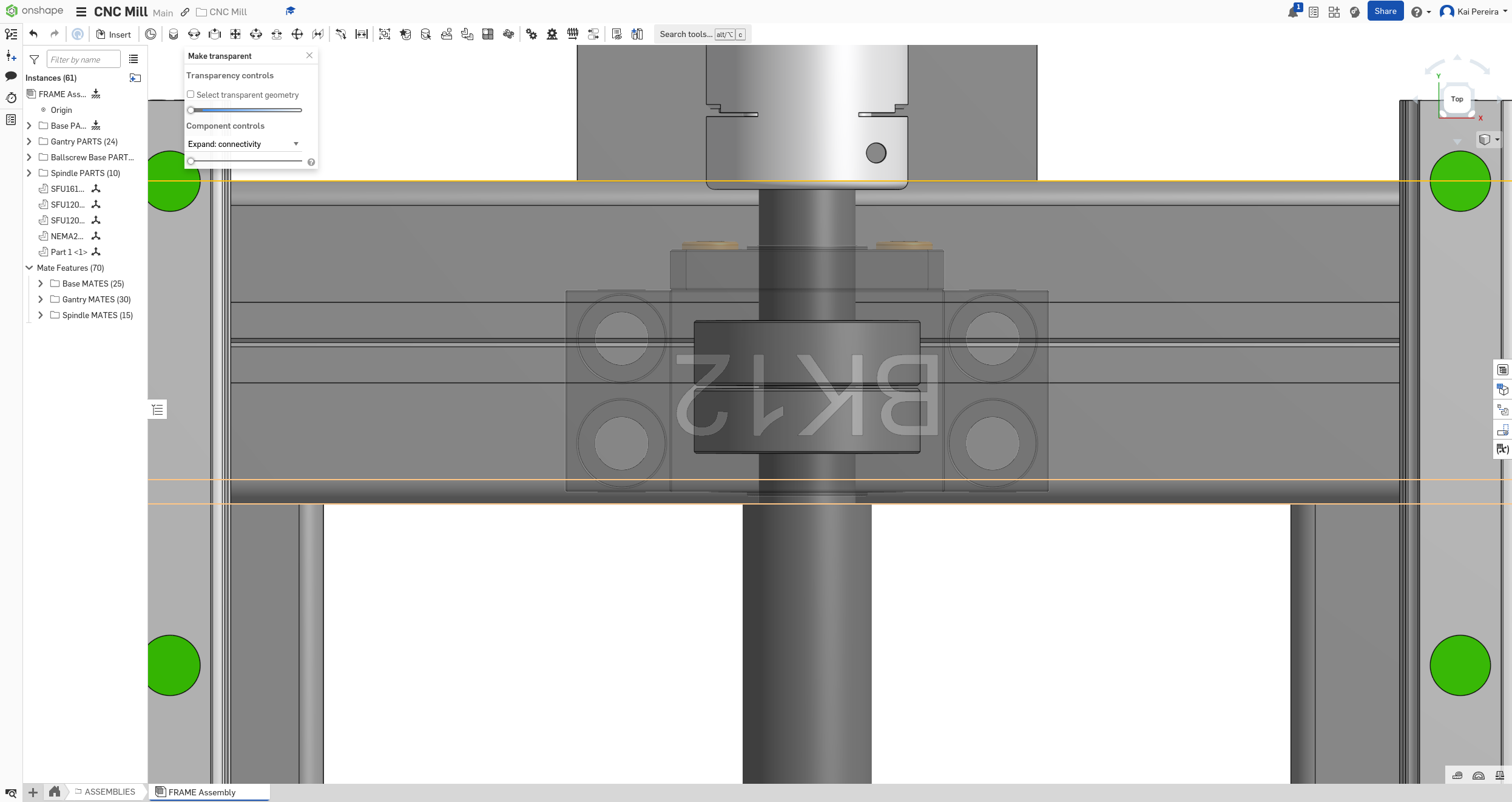
A couple of them happened to be a bit off, so I ended up modifying them a bit and now everything looks pretty to scale.
Anyways, it's time to work on the spindle ball-screw setup now, I need to increase the length of the plate so that I can attach the stepper motor easily.
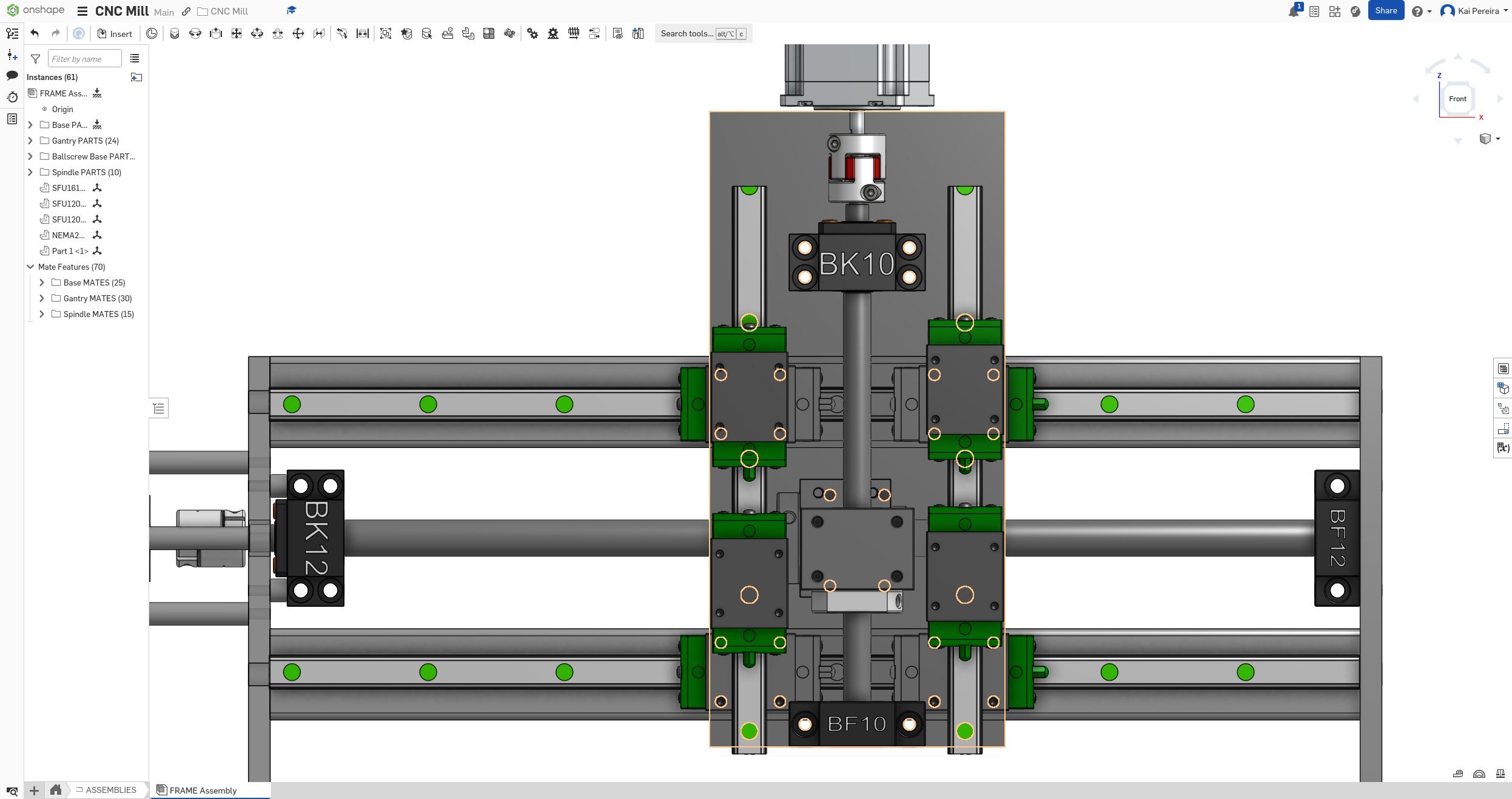
Now there's a couple of ways I can attach this stepper motor: - Some aluminum plates screws in to the plate and then upwards connecting the motor - An actual motor mount - 3D printer mount
I asked the PrintNC discord, and it turns out, the motor mounts can actually be 3D printed! They don't need to be as strong as the rest of the stuff, because it's mostly the supports taking the forces, and the stepper is really just turning, so the plate doesn't need to be crazy strong. So I decided on going with a 3D printer mount for the plate. I also really like this way of making mounts so I'm probably going to modify the bed mount to use a 3d printed mount too, because it's using aluminum right now and I feel like it's not the best option.
I'm going to be basing the design of this mount based off of Tom Stanton's design. The PrintNC guys said I should print in ABS or PETG and I think I could easily get my friend to 3D print me the mount in PETG. Anyways, let's design the mount.
I'm going to just use the dimensions of the NEMA23 mount I already designed and then just add the supports and such.
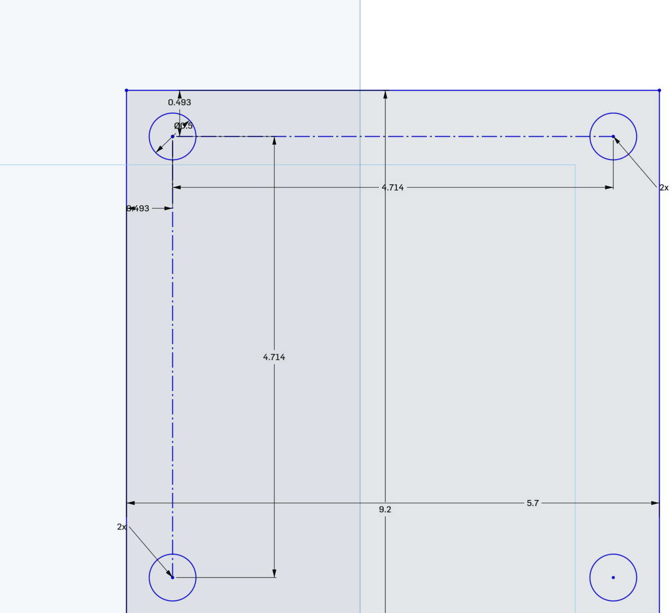
Anyways I'll just extrude that and see how it is. The cool thing about having everything very accurately designed, is that I can test stuff out and see how it is. Clearly it's not long enough so I can just make it longer, and then I'll add some fillets and such.

Anyways, while I was designing this, I got a message from the people at PrintNC who showed me this absolutely ingenious way of connecting the stepper.
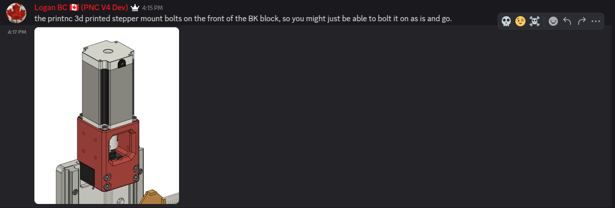
Thanks Logan! So I'm definitely switching to this because it looks really rigid and well thought out!
Anyways, I'm going to save this for tomorrow though as I've already spent quite a bit of time working on these things. Tomorrow I want to finish the stepper motor mount and get the spindle on!
Total time: 77 hours
Day 26 - Actually wrapping up the spindle
Anyways I want to design something like this to act as a motor mount on my spindle assembly.
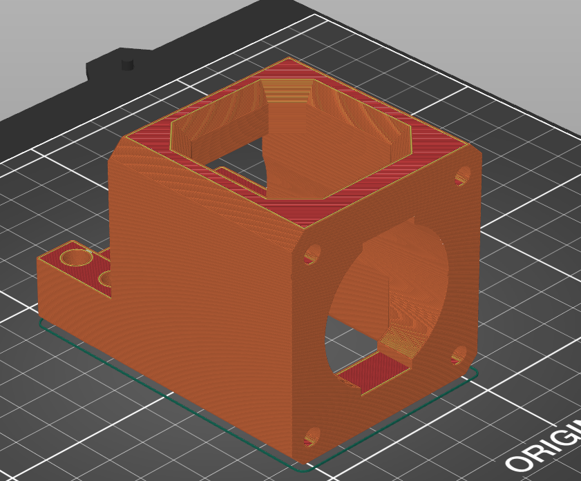
This will keep the stepper rigidly attached and I can print it in ABS or PETG. Now I've already designed a mount but it's way less rigid from this one.
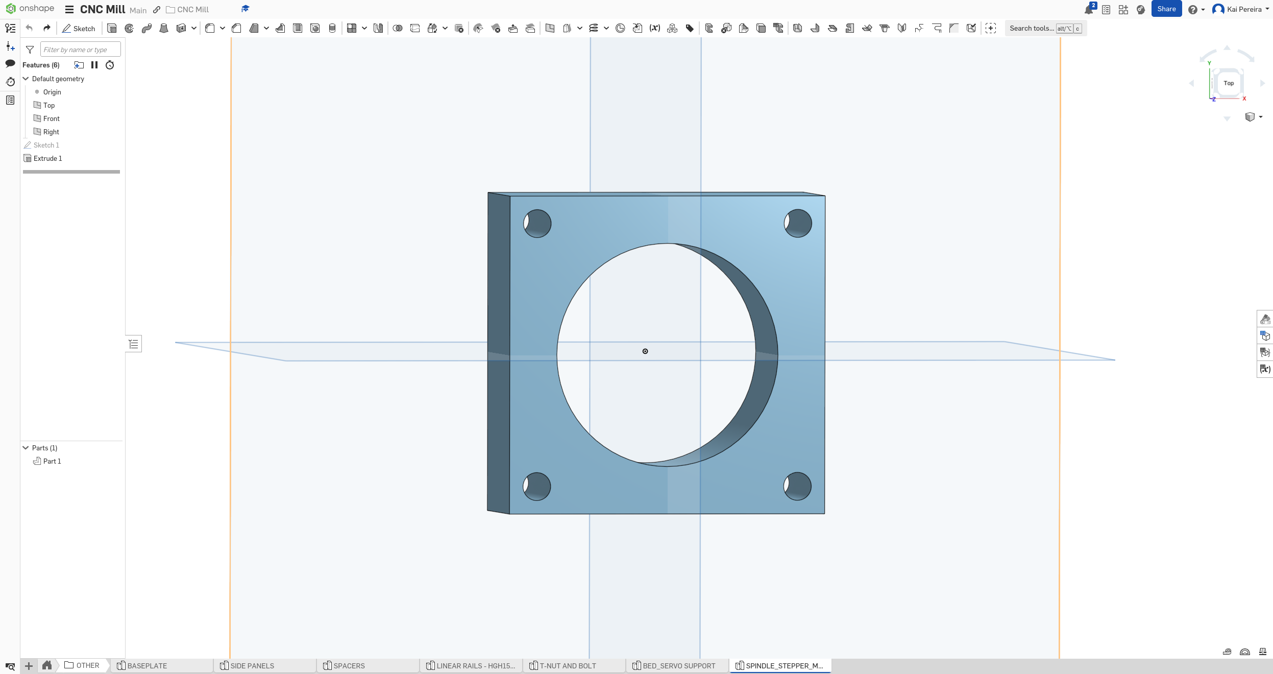
The good thing about what I currently have, is that it's one of the faces of this new mount so I can still keep it. I just have to model the BK support and the other faces.
Now one of the things is that the stepper actually goes underneath the top face of the plate, so I need a little divot that will attach to that and maybe go into the plate too. So let's get designing!
First I'll make that little piece that connects to the BK support. I've spent a lot of time working on this piece and after maybe like an hour I'm here:
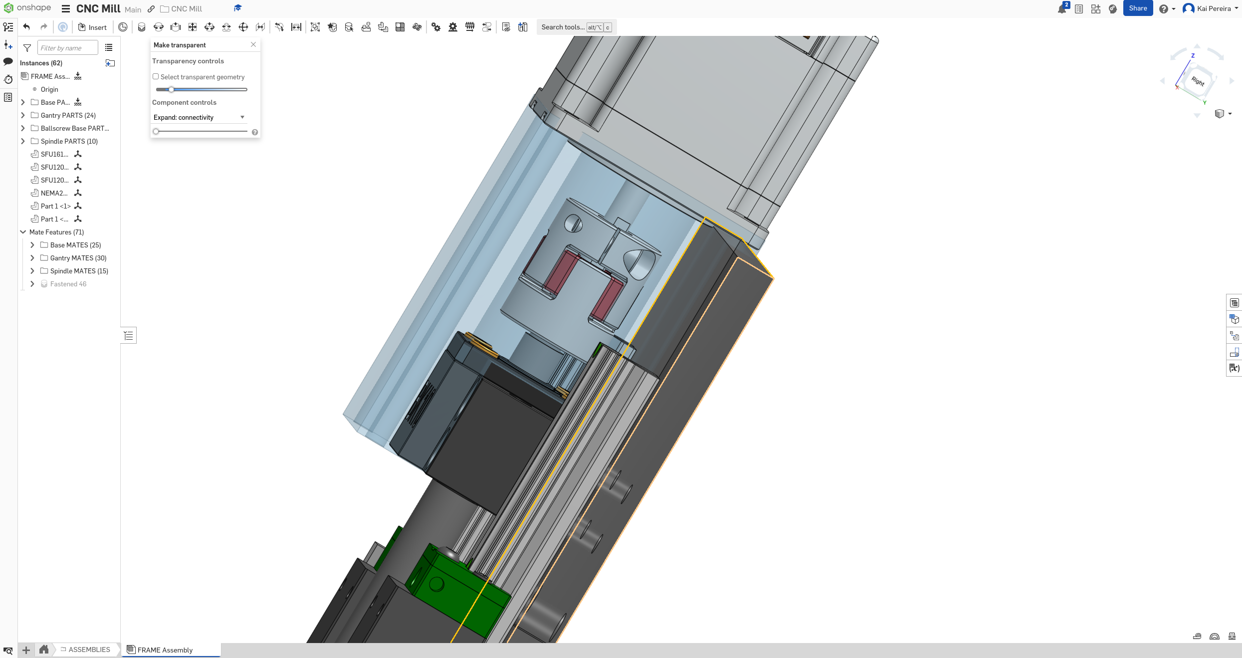
I keep on messing up the measurements and such so I keep on having to re-iterate. It still needs lot of work though but it's definitely coming along!
Anyways after a little bit I wrapped it up, looks pretty good!
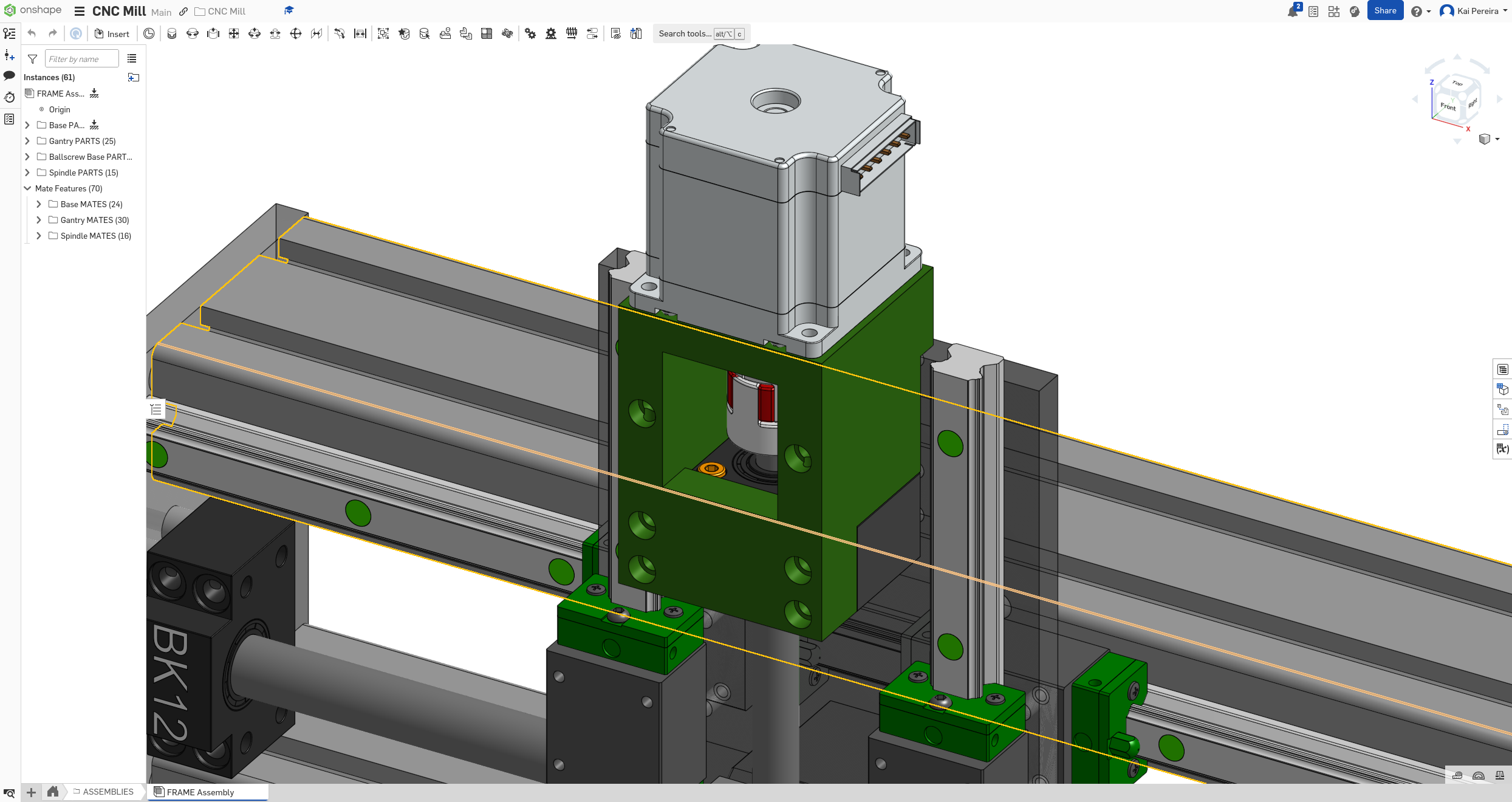
I'll just end today off here and then tomorrow I'll work on the next motor mount!
Total time: 79 hours
Day 27 - Another motor mount
Today I wanted to build a second motor mount for the stepper on the X axis. Currently it just uses aluminum blocks to attach it on which I don't feel like is going to be too simple.
I honestly don't really want to describe the whole build process because it took quite a bit of time, but there wasn't actually much interesting.
I just took the datasheets of the BK12 support and used the Z axis mount design to model this new one. The only different with this one is that I wanted to actually strengthen the support a bit more, so I bolted it to the extrusions vertical face to really make it strong.
This took about an hour and half but it looks pretty good!
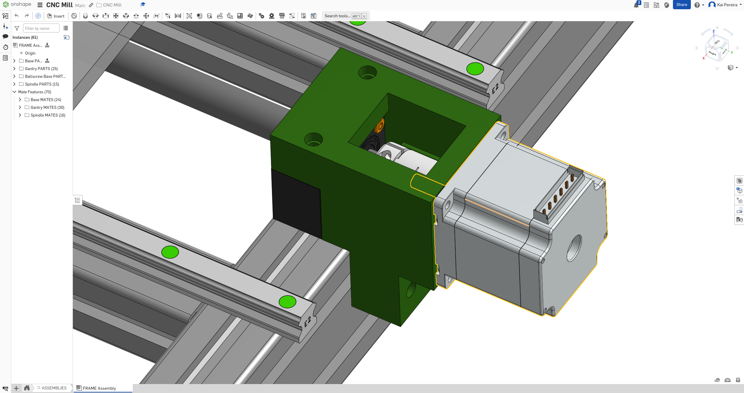
Now our mills is looking pretty good with the new mounts, I actually don't really see any parts that are looking a bit out of place and are hard to assemble.
I really want this mill to be easily assemblable and simple so I don't want like some weird bits of like aluminum bolted together to create a stepper mount.
But anyways here's a photo of the current mill:
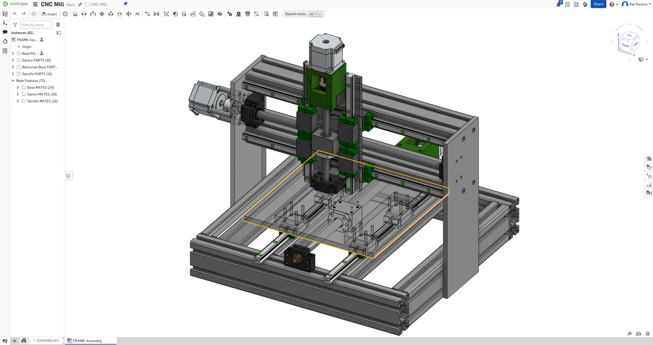
On a side note, I applied to this program called Bagel Fund and they give grants to cool projects like mine. It's a really cool concept and they give $100 to $500 micro-grants which are really impactful for projects like mine. So I need to book a call and hopefully I'll maybe get a $400 grant or something like that :D
Check it out: https://bagel.fund/
Anyways I also quickly fixed a problem in the assembly where the coupling wasn't turning when the spindle assembly was moving back and forth, I just fixed the coupling to the ball-screw instead of just having a revolutionary mate on the stepper!
Now I have a couple of options for what I can work on next: - Fix the bed, because currently it's just randomly sized pieces of aluminum, I can definitely use like stock material and such instead - Work on the spindle some more, getting the plate on there and maybe attaching the actual spindle
And really I think those are the 2 main things I currently need to work on.
I'm going to work on the spindle plate though, just because it gets a lot of progress forward and then I can attach the actual spindle on.
Anyways I really want to just have like one plate on the spindle assembly but I'm not too sure how I would make the indent into the plate so that the ball-screw could fit on.
Now there's a couple of options I could opt for, for the bed, I just sandwiched some other aluminum plates on it because it was quite the gap, but for this I can do some other things: - Thick spindle plate that is machined to fit the ball-screw housing - Machine to plate they're currently on to indent it into the plate - Again doing it sandwich style and just putting the aluminum standoffs basically
Anyways before I even think about that, let's figure out the exact distance between the rails and ball-screw housing. If you ever find yourself doing something like this, just do it in excalidraw on on paper, it's so helpful (EXCALIDRAW IS SOOO GOOD).
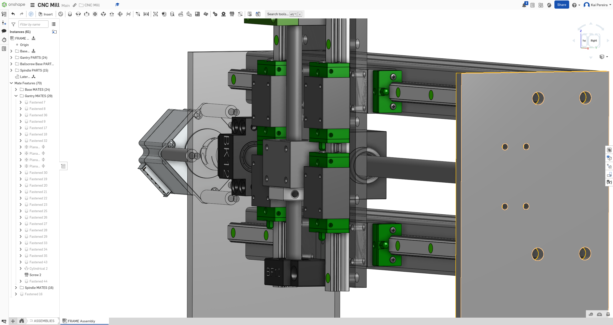
AND I JUST DISCOVERED THERE'S EXCALIDRAW FOR OBSIDIAN WHICH I'M USING. My mind is absolutely blown!!!
Anyways, doing some quick math we can find that it's exactly 9mm between the 2:
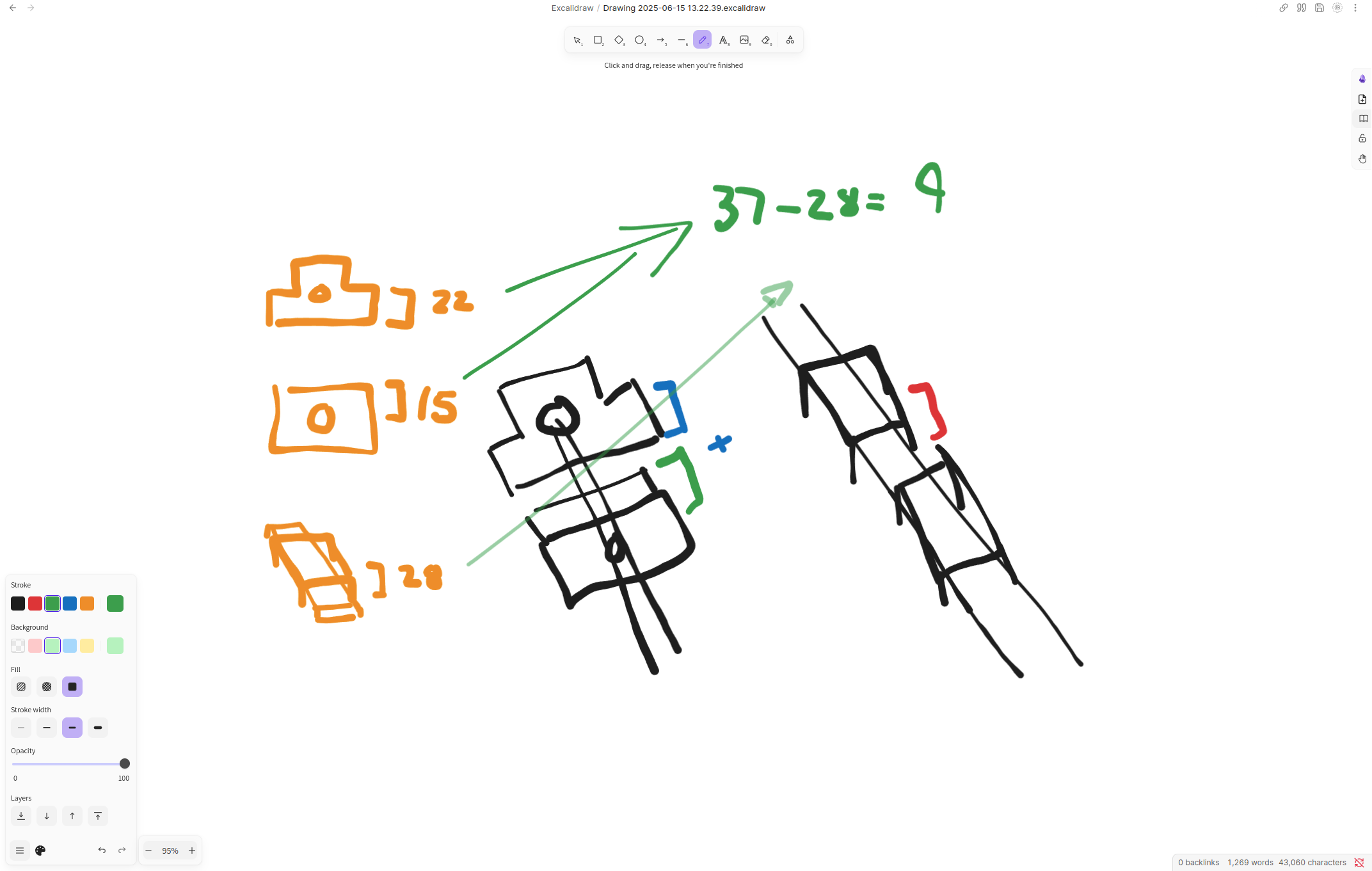
Quick verification too, you don't really need to do this because you're going to model a part with the same dimensions either way, but I did it to demonstrate.
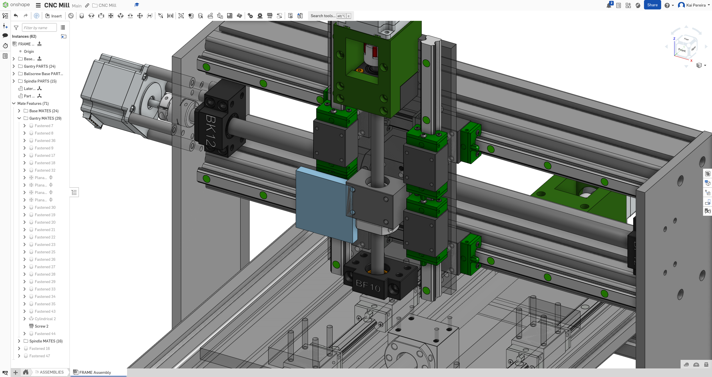
Anyways, because the gap is 9mm, I can get away with using a stock piece of 3/8", which is 0.953 cm, so I will just have 0.53 mm of space between the ball-screw and the plate, which should be pretty much negligible, although I should probably so a bit more research into this.
A mistake I made with the bed wasn't giving some leeway with the metal attached to the rails so there's a lot of wasted material, I'll fix this later, but I don't want the spindle to have this. Everything should be as close as possible to reduce vibrations and increase rigidity.
It's pretty simple to design the plate, it's just going to be double the height of the carriage and the same width with holes, so let's design it!
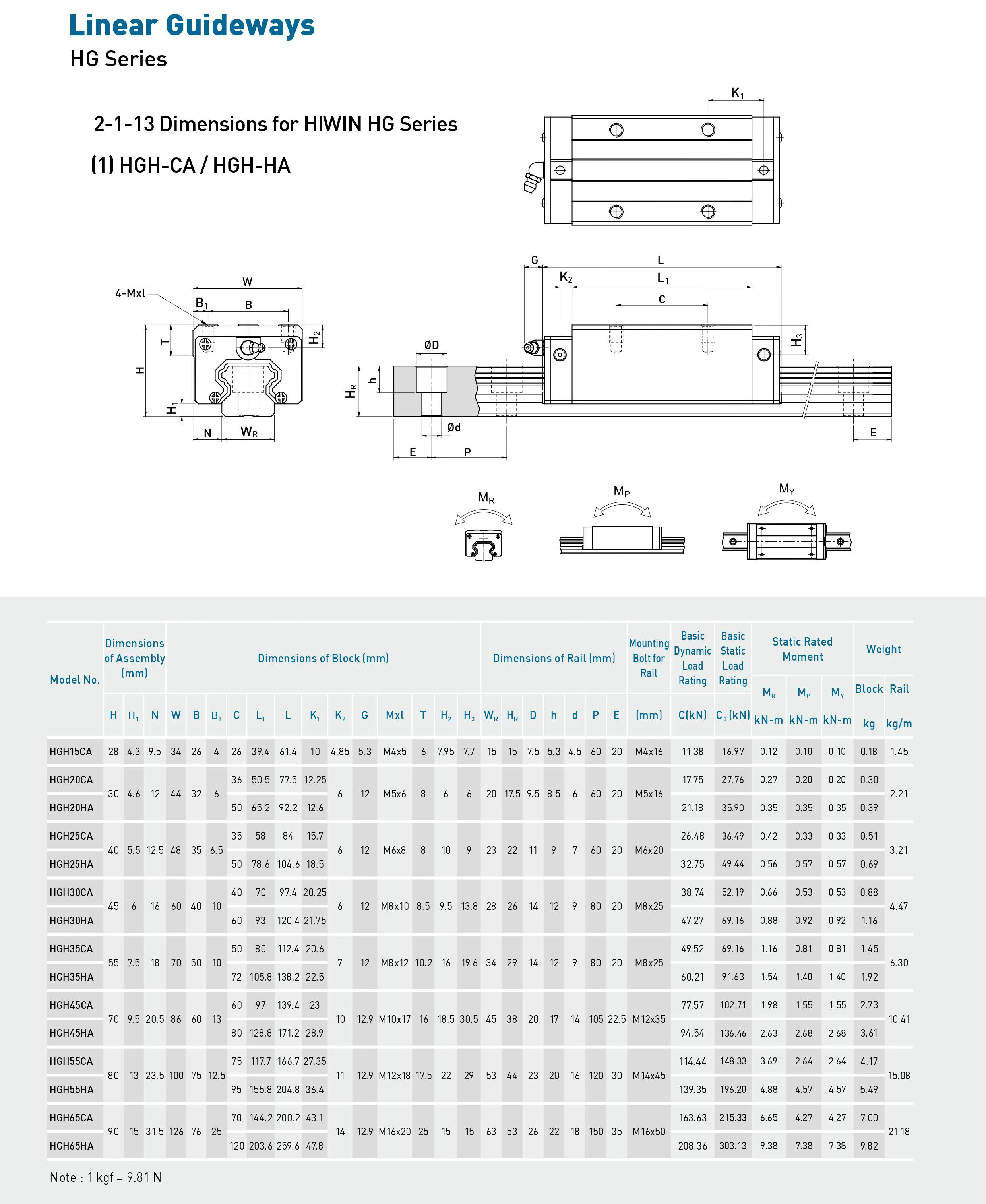
So we take this, just use the height and width, and boom:
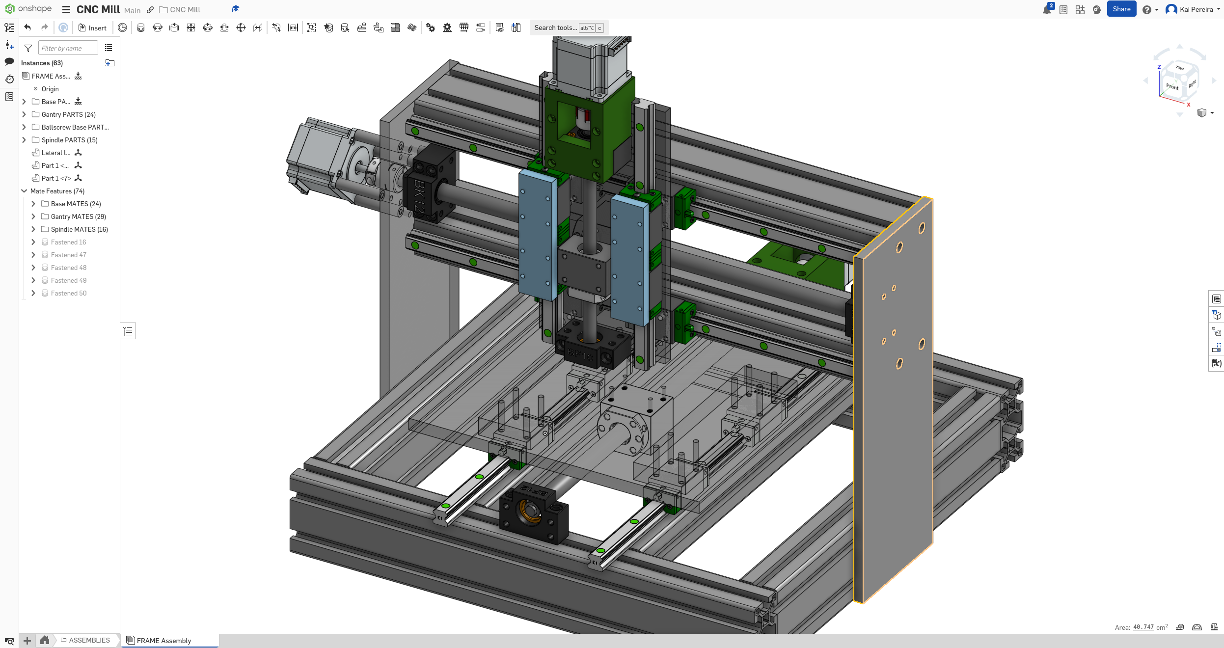
Now we have some exact plates, and I designed them in a way where I can easily make them bigger and smaller depending on when I need them.
Anyways those mounts took a lot of time and I managed to get some work on the spindle. It's june 15th, so I'm already 4 days behind, but that's because of a lot of procrastination.
Tomorrow, I know I can finish the spindle, and fix the bed, and then I can put the finishing touches on the mill!
Total time: 81 hours
Day 28 - Grinding it out
Today I just want to power through the spindle and bed and then tomorrow I can do finishing touches. Let's just get the stuff done!!
First I'm going to start working on the spindle plate, it's got pretty simple dimensions so it's really easy to implement.
And just like that, we have a plate we can put our spindle on!
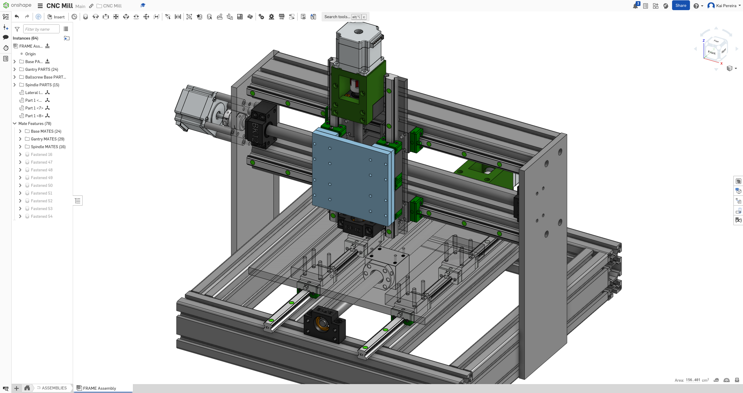
But now we have some even bigger problems, the plate intersects the BF, BK and motor mount supports!
This means that our range of motion is MUCH lower:
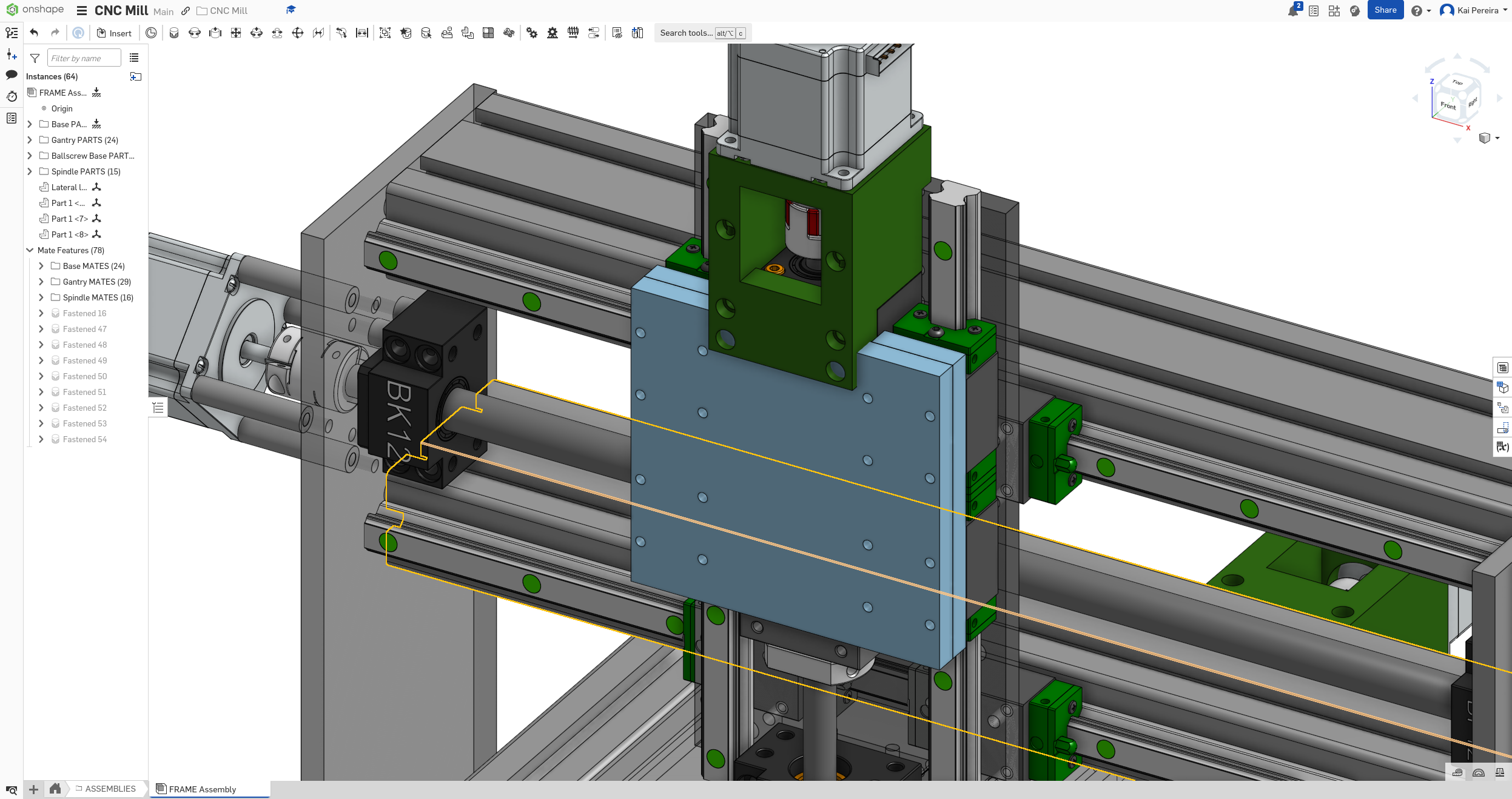
The BK support and it's motor mount seem's really difficult to fix, so I'm going to focus on the BF support which would give us nearly 2cm of more space!
You can see the intersection is really mild on the spindle, just about a couple of mm.
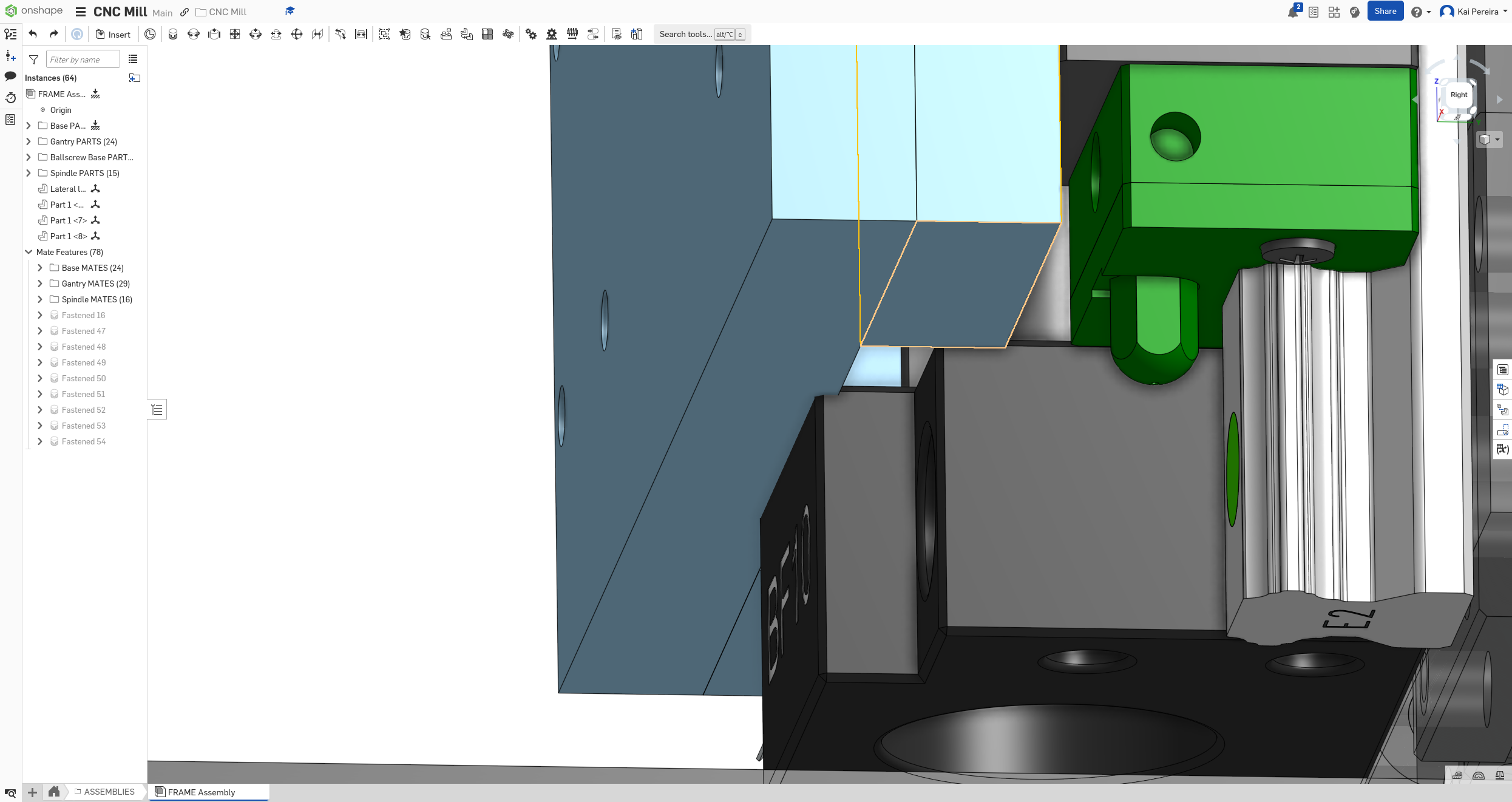
With this in mind, we have a couple of options we could do: - Indent into the plate about 3mm so it just passes over the BF support and then add a spacer - Increase the height of the spindle plate supports (the ones on the rails) and then add a spacer - Cut into the actual spindle plate so that there's space for the WHOLE support to pass through -> not the most optimal but simple
Honestly I'm not too sure what to do so I'll ask the guys at PrintNC.
Anyways after a bit, they told me that sandwiching would probably work best, so I increased the amount of material on each spacer and added material to the ball-screw, to create this NEARLY flush surface.
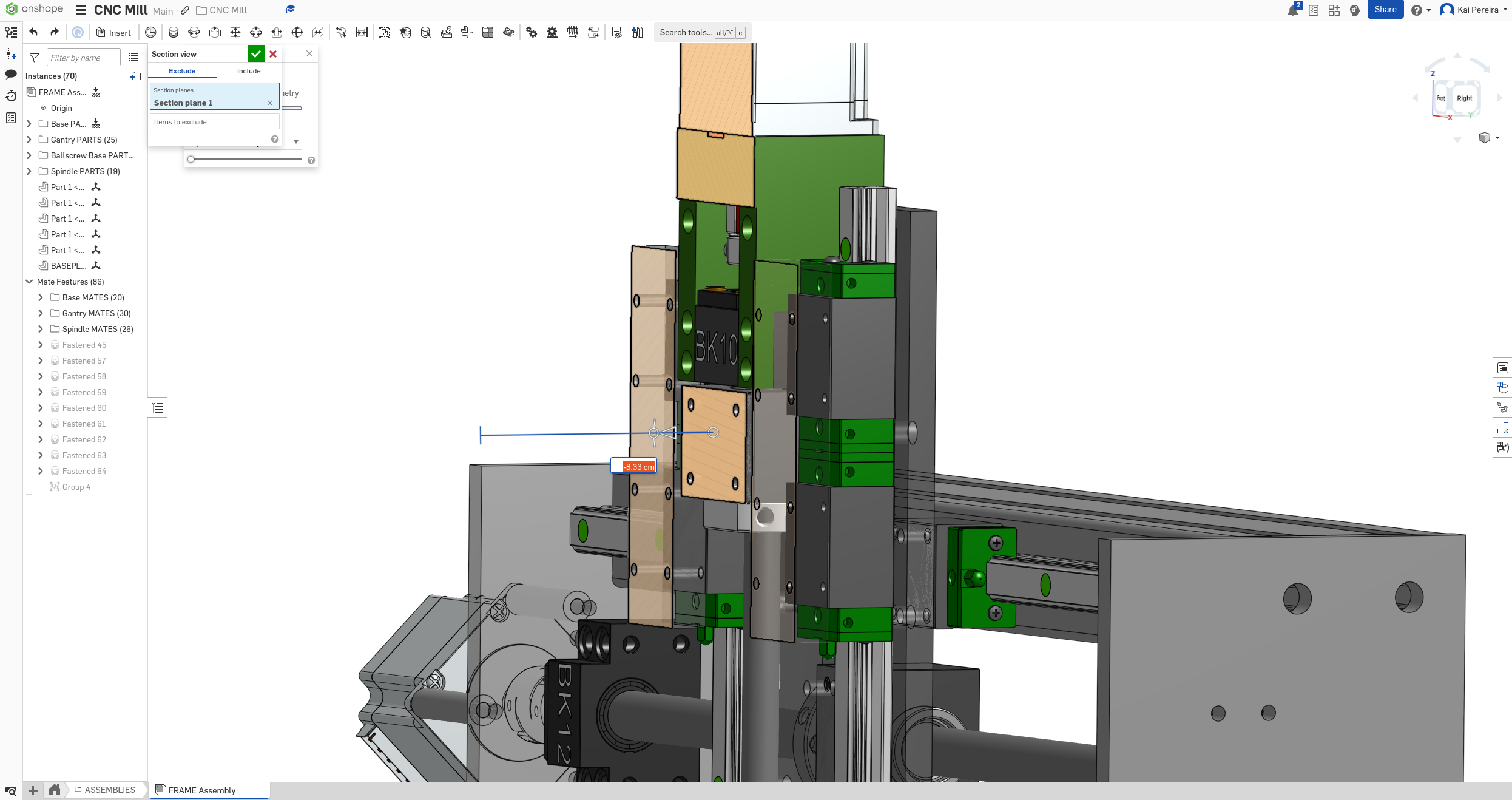
Anyways, now I have to modify the ball-screw mount a bunch to actually let me have all of this clearance but it isn't too complicated:

Now there's another problem, our current ball-screw position doesn't give us this clearance! It's intersecting with the mount, so now we have to fix that third thing, I'm just going to move the ball-screw down for this and I think the rigidity will be fine!
I also added the spindle here just because it's a couple screws and pretty simple to put on and helps me with my calculations!
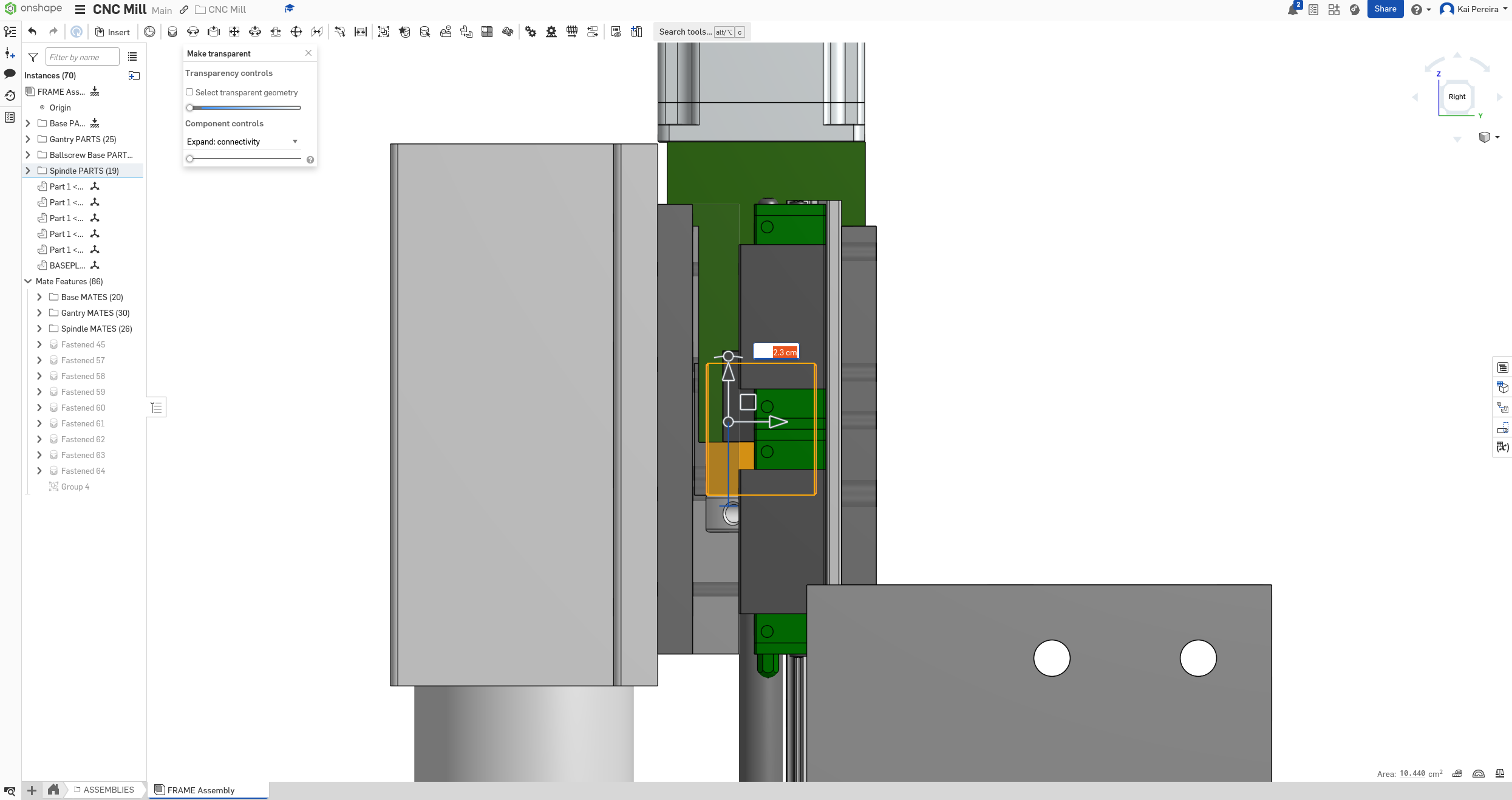
For this, I'm going to simply bring the ball-screw down to the point where it's just above the BF support of the assembly which should be about the perfect distance (3.4cm)!
And I'm liking this! I get about 13.5cm of travel which is pretty good, the rails can't fall off because the ball-screw hits the support first and nothing seems to be intersecting!!!!
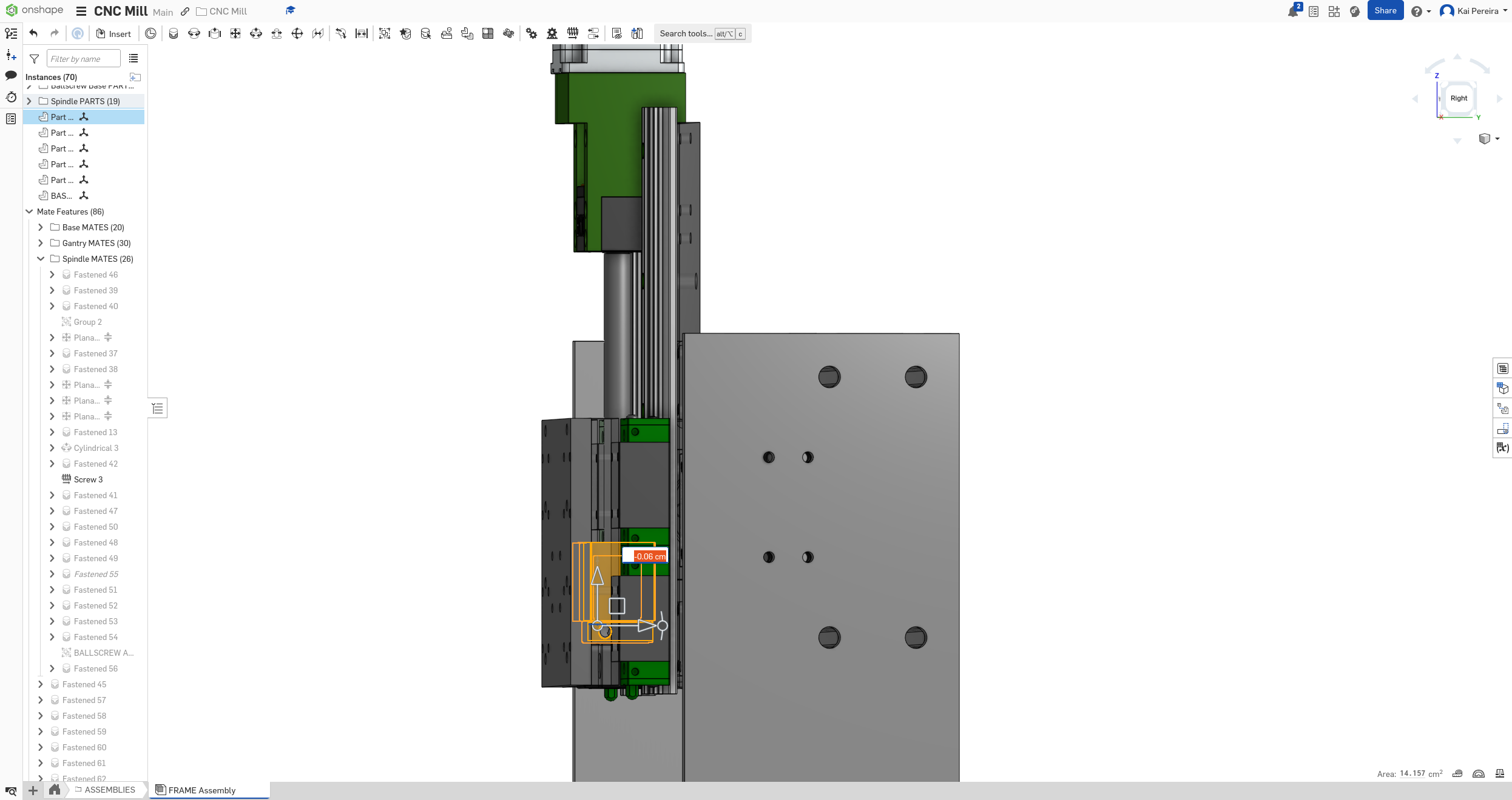
Anyways the gantry's looking good so I'm going to end if off there!
It takes a lot longer to actually do the stuff than I make it seem, I'm doing lots of calculations so today took about 2 hours!
Total time: 83 hours
Day 29 - Polishing the bed and other spots
The spindle looks really good, so now I want to polish up the bed so that it's production ready. There's quite a few things I still have to do for it: - Use stock material for the bed and spacers so that it's way cheaper - Make sure there's clearance on the supports - Polish up all the temporary janky stuff I had in
First I'm going to use stock widths for the spacers and bed and such. The bed needs to be quite tall to clear the supports.
I calculated that there's about 1.7cm of space between the carriages and the ball-screw so I need at least that much space. I'm going to use a 3/4" stock for this which will give me 1.9cm of clearance, so the gap between the ball-screw and the bed will be about 2mm, which will be fine, but I'll probably add a shim.
This is also enough to clear the supports so it's pretty perfect.
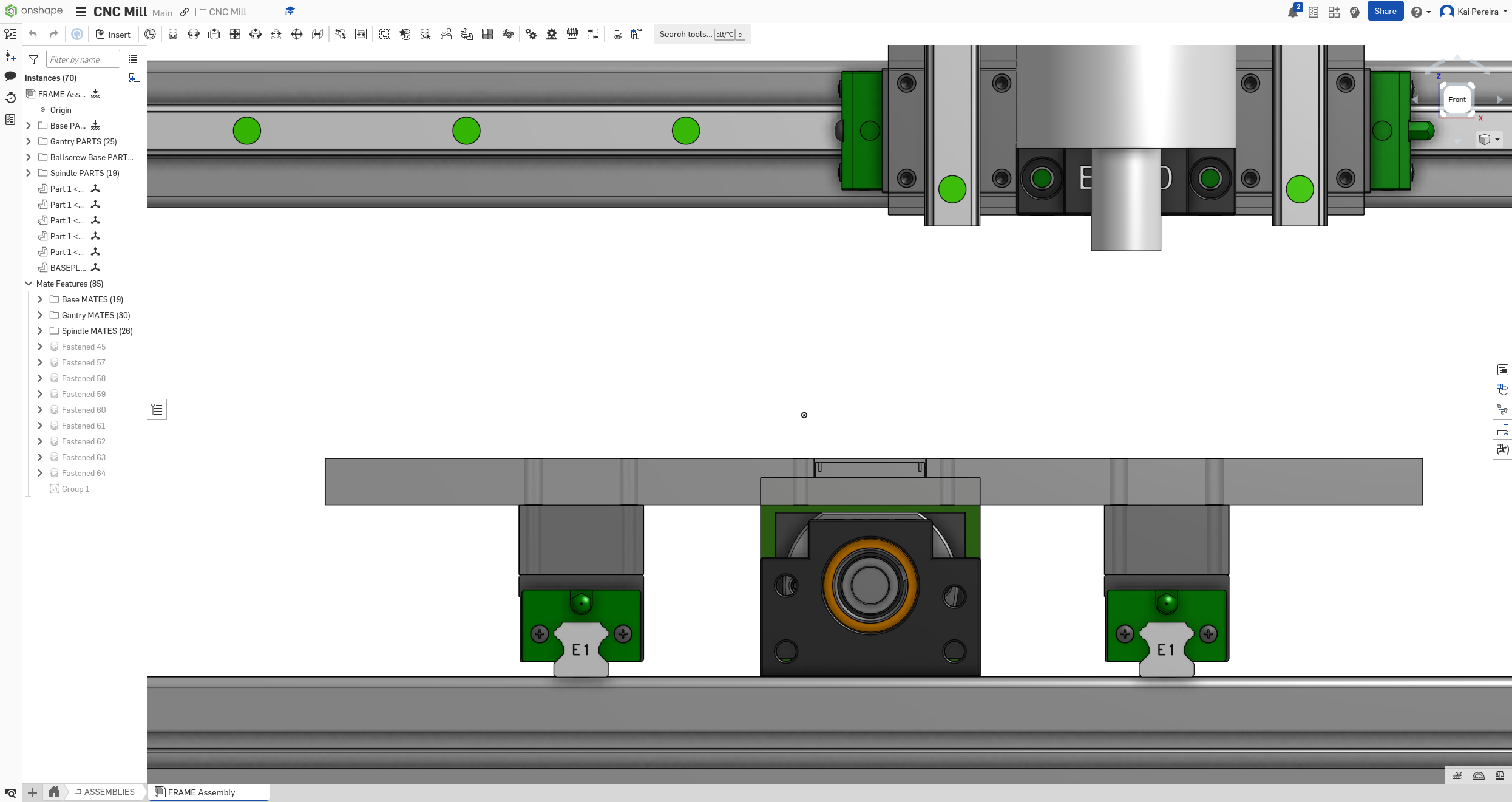
I also need to move the ball-screw nut so it makes the most effective use of the available rail space and so that the carriages don't just fall off. This is fairly simple, I'll just move the nut.
Now the ball-screw lines up pretty nicely with the end of the rails (on both sides, I just didn't show the other side:
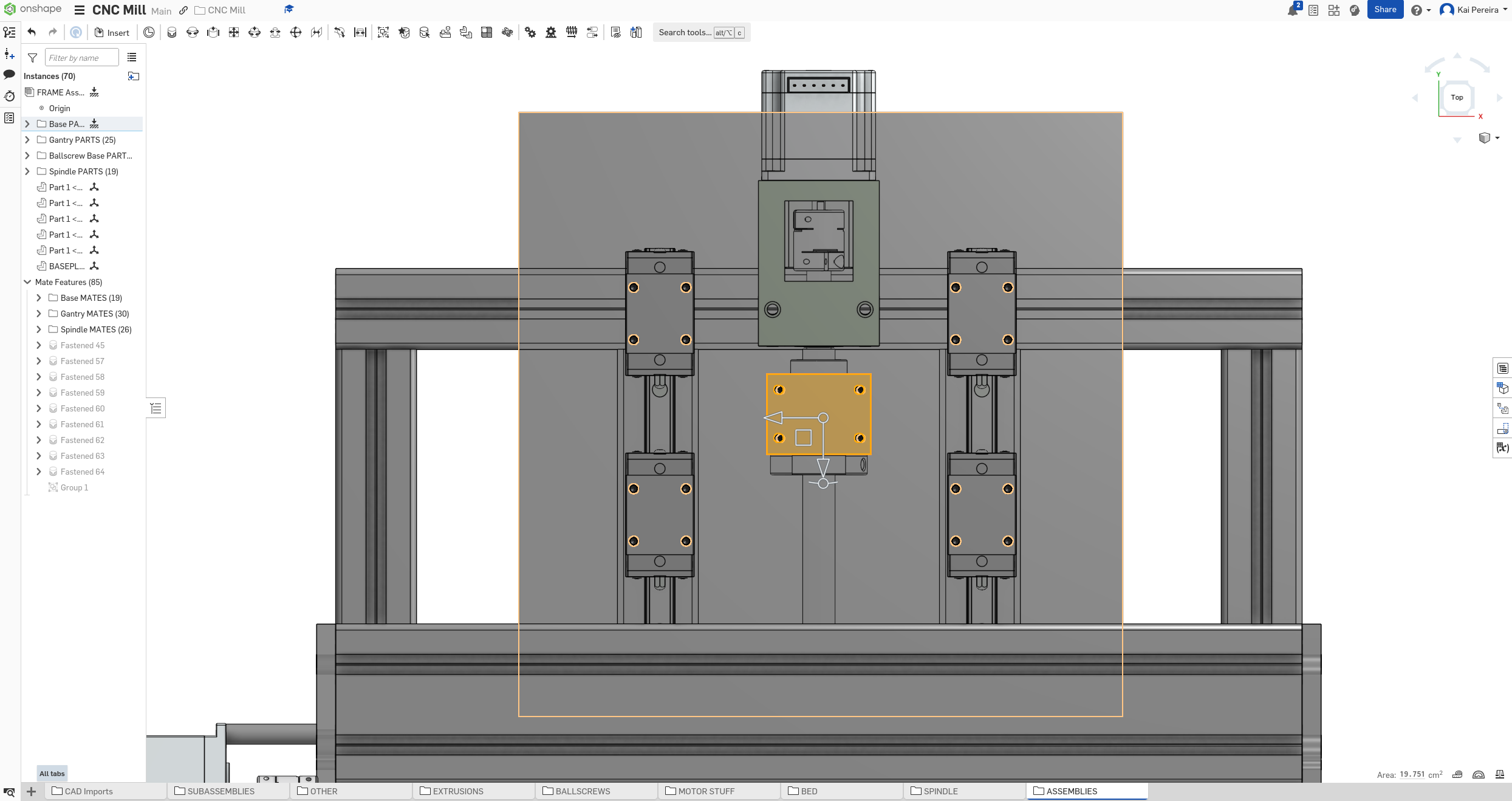
Big problem though, the bed intersects with the stepper mount support, so it'll just hit it....
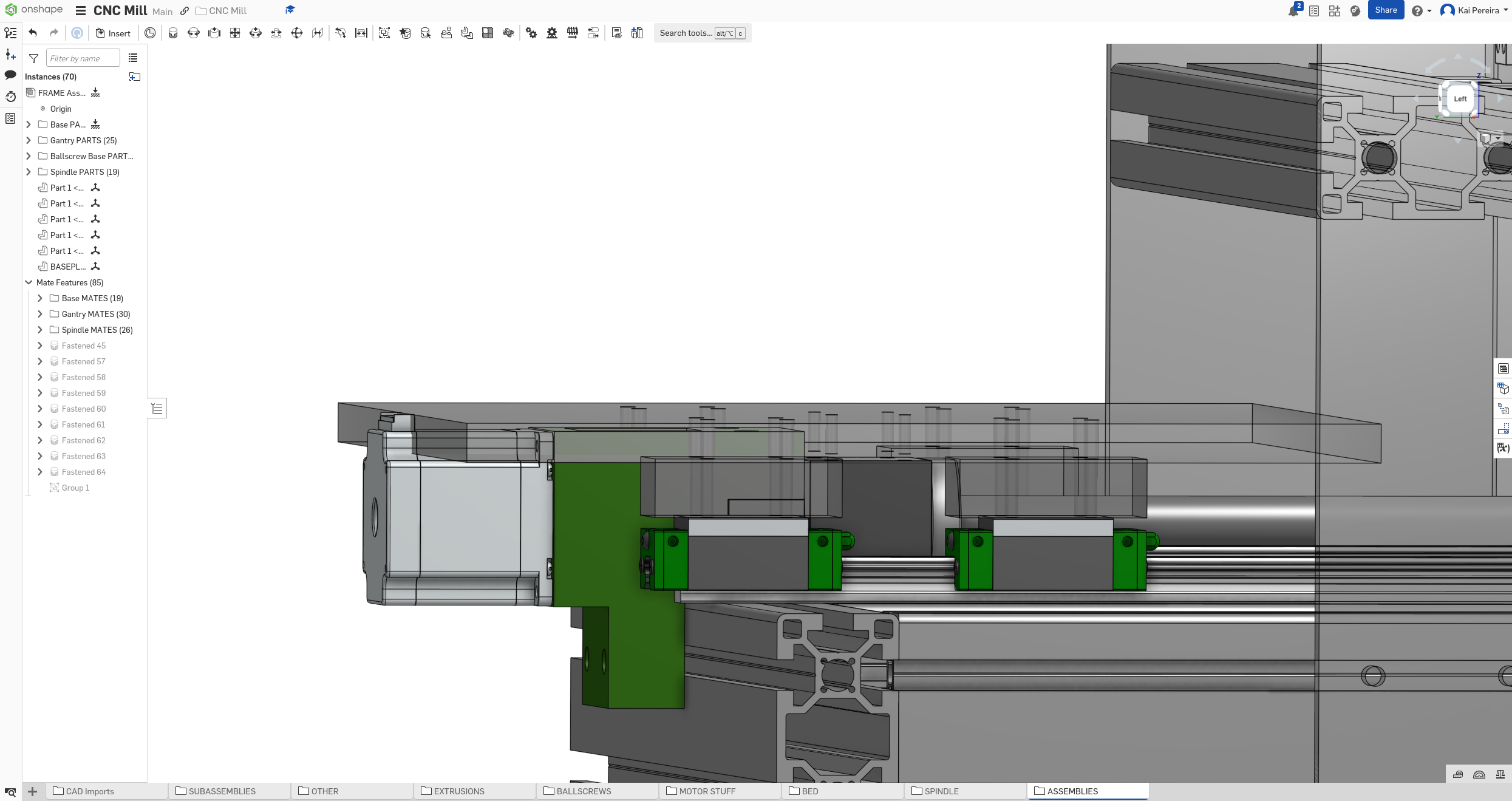
I'm going to leave this problem for future me though and instead work on attaching the extrusions together properly. I want to use like T-Nuts/bolts but I have to tighten them through the extrusion because they're perpendicular to each other.
This means I have to drill holes on some of the extrusions so that I can actually tighten the extrusions together.
Really, the only holes I need are some on the faces of the longer extrusions like so:
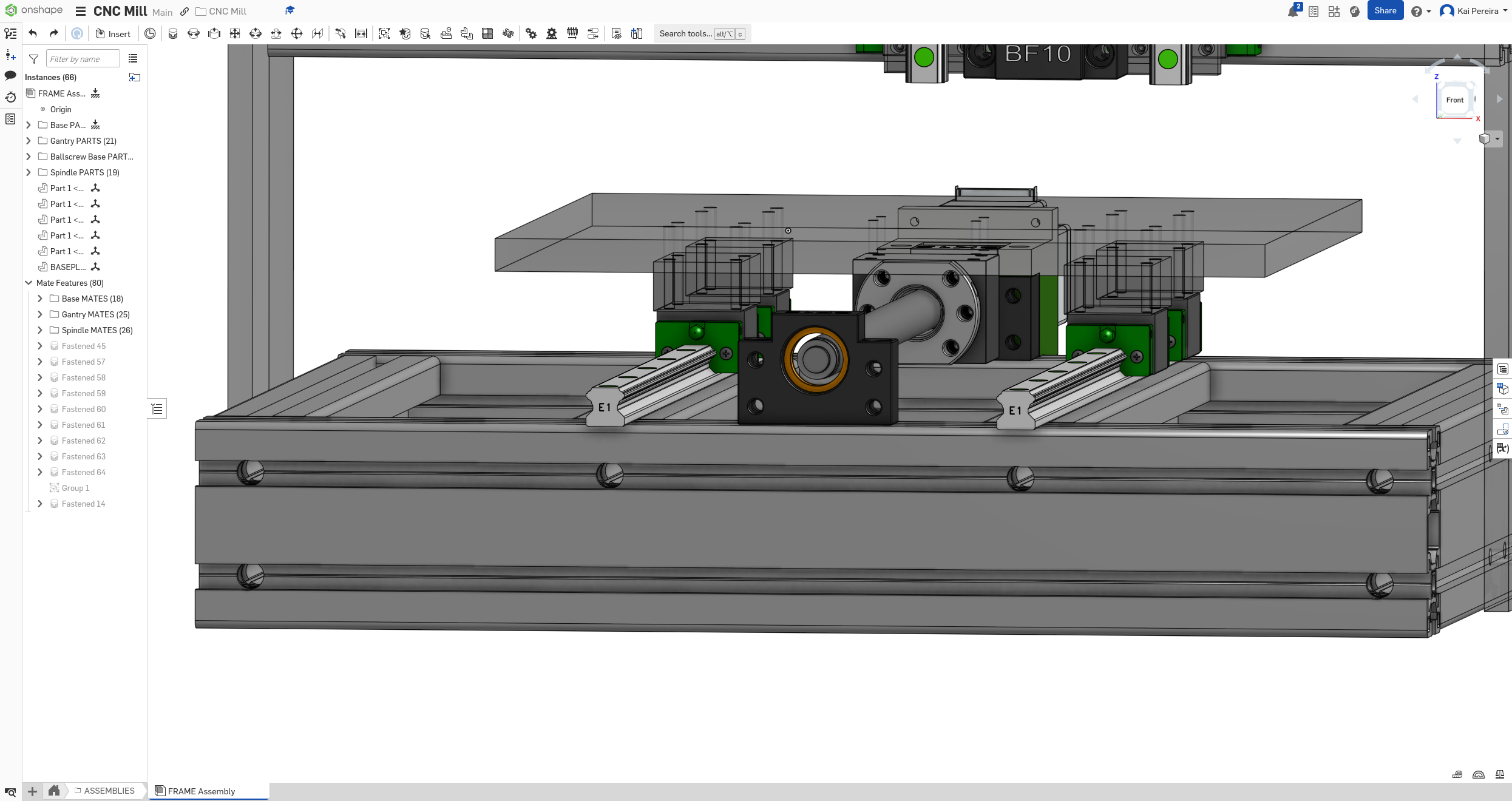
This will let me tighten all the tapped holes of the other extrusions.
Now I kind of need to figure out how the other components are going to be attached. I've already researched T-Nuts and stuff
Day 30 - BOM
Now the CNC mill is pretty done, I need it to be nearly finished by June 25th so I can qualify for a hackclub thing. This means I need to get the BOM in place.
I'm just going to be adding all the stuff into the BOM as I go through my mill and make adjustments accordingly if I see anything a bit off.
I'm going to be using Google Sheets for my BOM and I'm going to format it like the PrintNC because I like how they did it, but I'm also going to add a couple of fields.
![[Pasted image 20250621122426.png]]
Because I'm using specific parts I'm going to have a price and a supplier field so now my current sheet looks like so.
![[Pasted image 20250621122546.png]]
Anyways from now on I'll just add updates whenever I see something a bit off in my design.
The first thing I found off was my gantry plate, which just uses cm instead of inches.
![[Pasted image 20250621122637.png]]
The measurements are similar to inches so I'll just adjust it accordingly. Currently the carriages on my rails don't have that much clearance so when I make the plate bigger I'm going to increase the clearance. And now the plate is properly reflected (though it is off by about 0.3mm or so because I didn't want to have to deal with onshape rouding issues)
![[Pasted image 20250621130446.png]]