
Driver Board
Total time spent: 86 Hours
Day 1 - This is a bad idea - July 20th - 6 Hours
I've decided to build a complex 3D printer driver board, similar to the Manta M4P or the SKR Mini E3, but with some added features I have yet to decide.
I'm not too good at PCB work, I've only designed like keyboards and macropads and such, so I'm excited for a way harder PCB project!
The problem is, I have just about 10 days to complete this entire or I won't get the grant! So let's get right into building it.
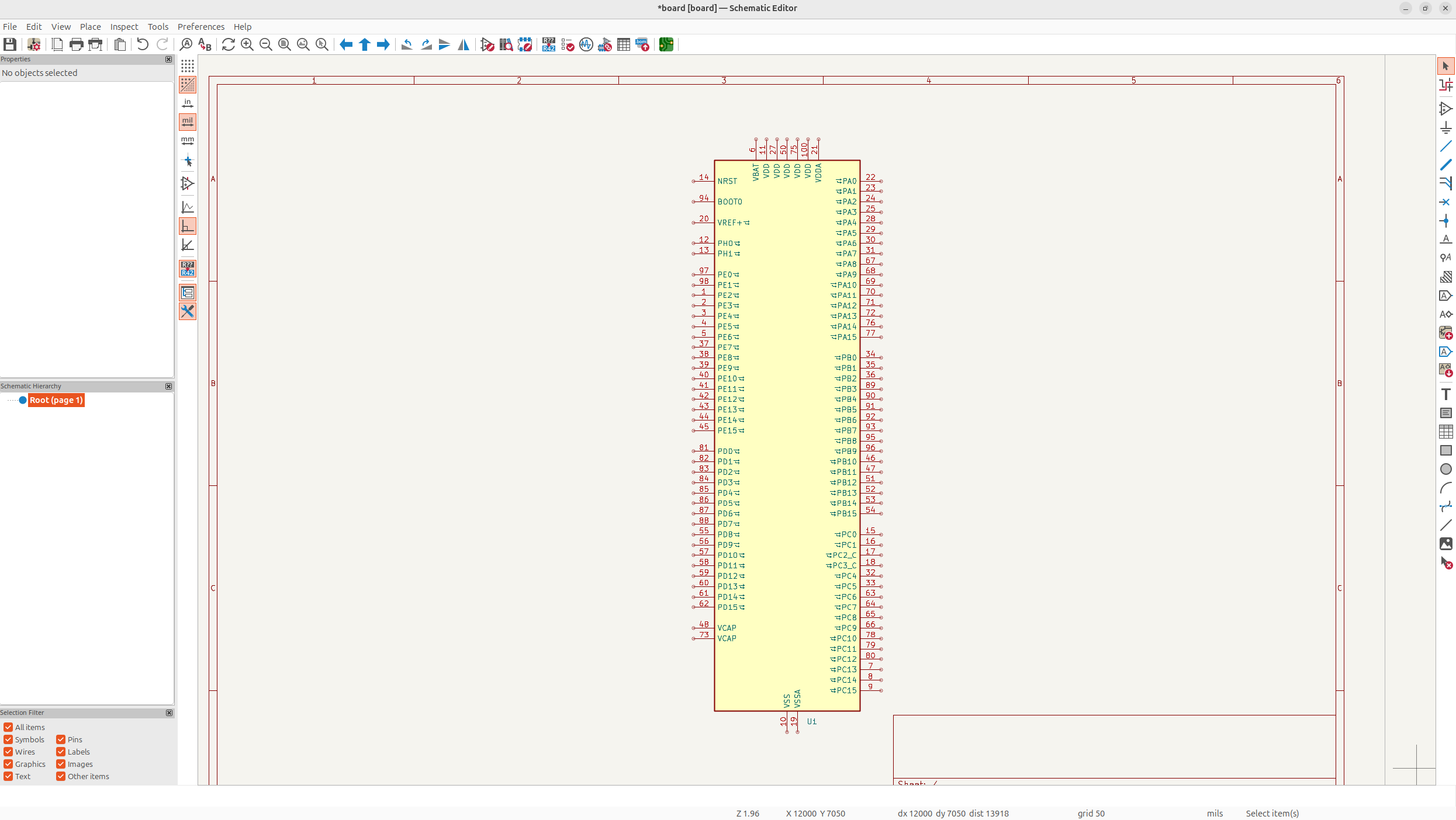
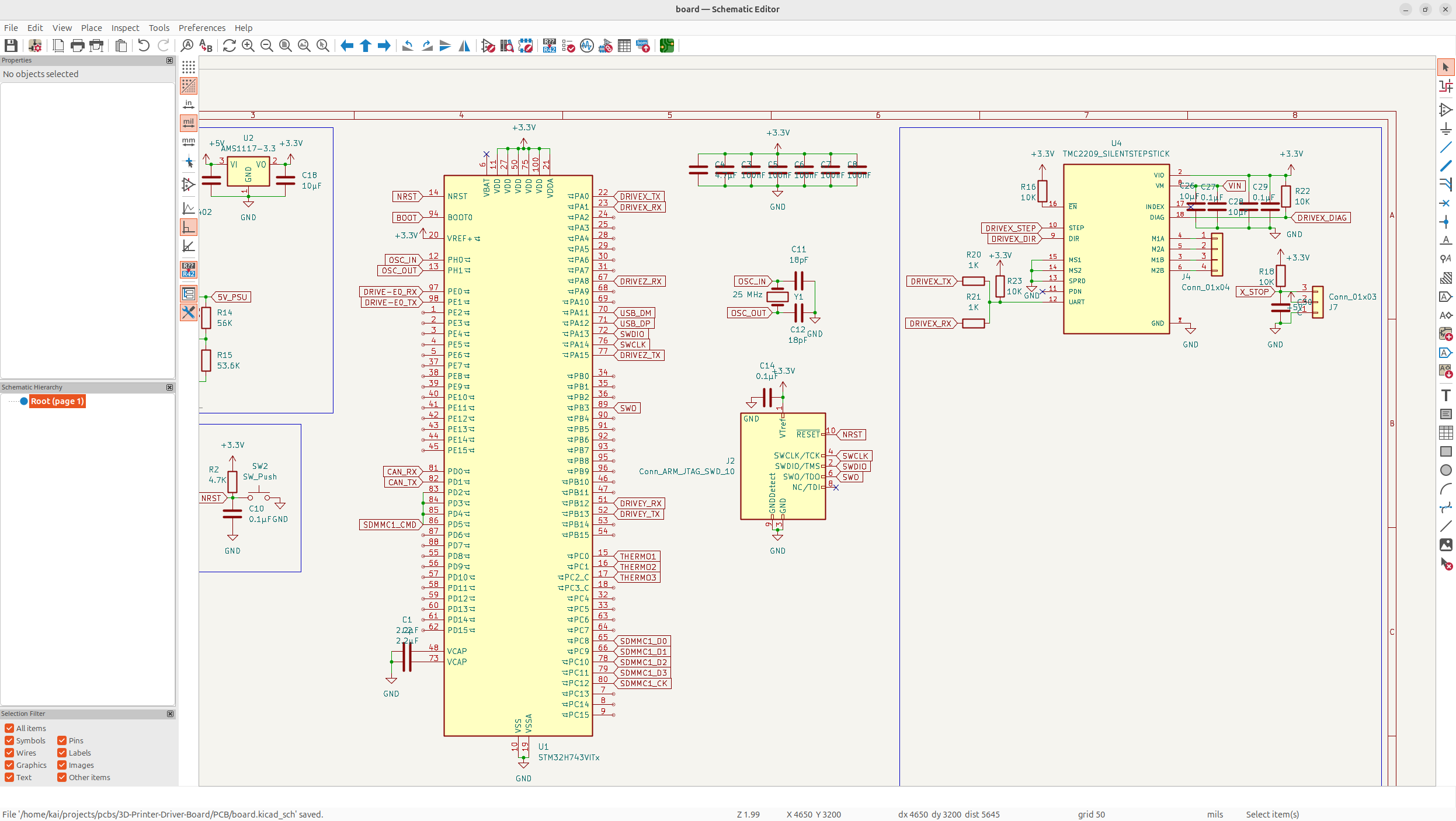
The first thing I had to decide on was the MCU. I decided on using the STM32H743, it's an insanely powerful MCU that has many features I love: - 2 MB Flash, 1 MB Ram (for firmware and G-Code Interpreter and stuff) - Ethernet MAC (so I can network the printer) - 480 MHz Processor - Support for every communication protocol imaginable - Good firmware support - Blazingly fast and powerful
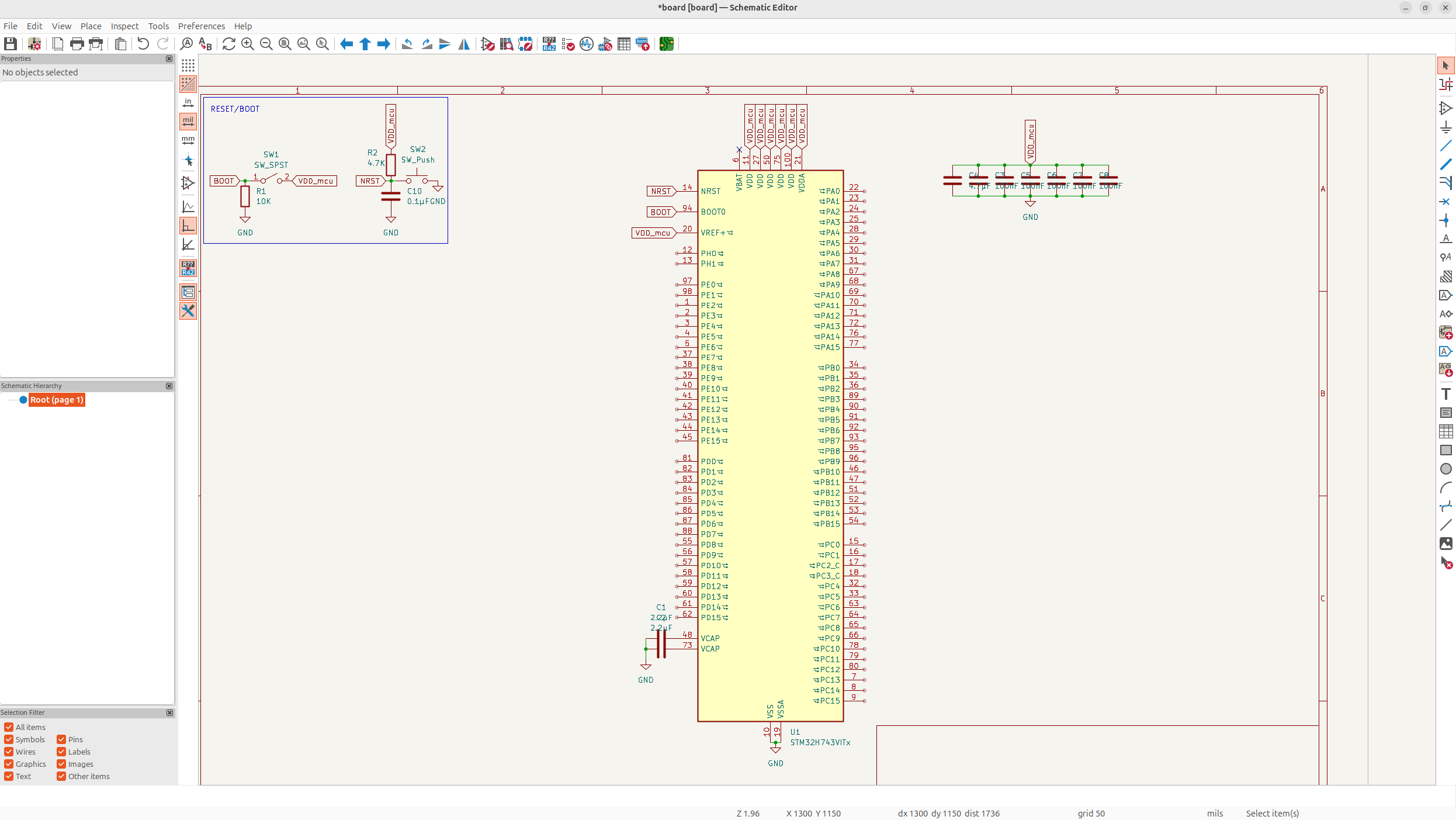
So let's just add in the MCU:
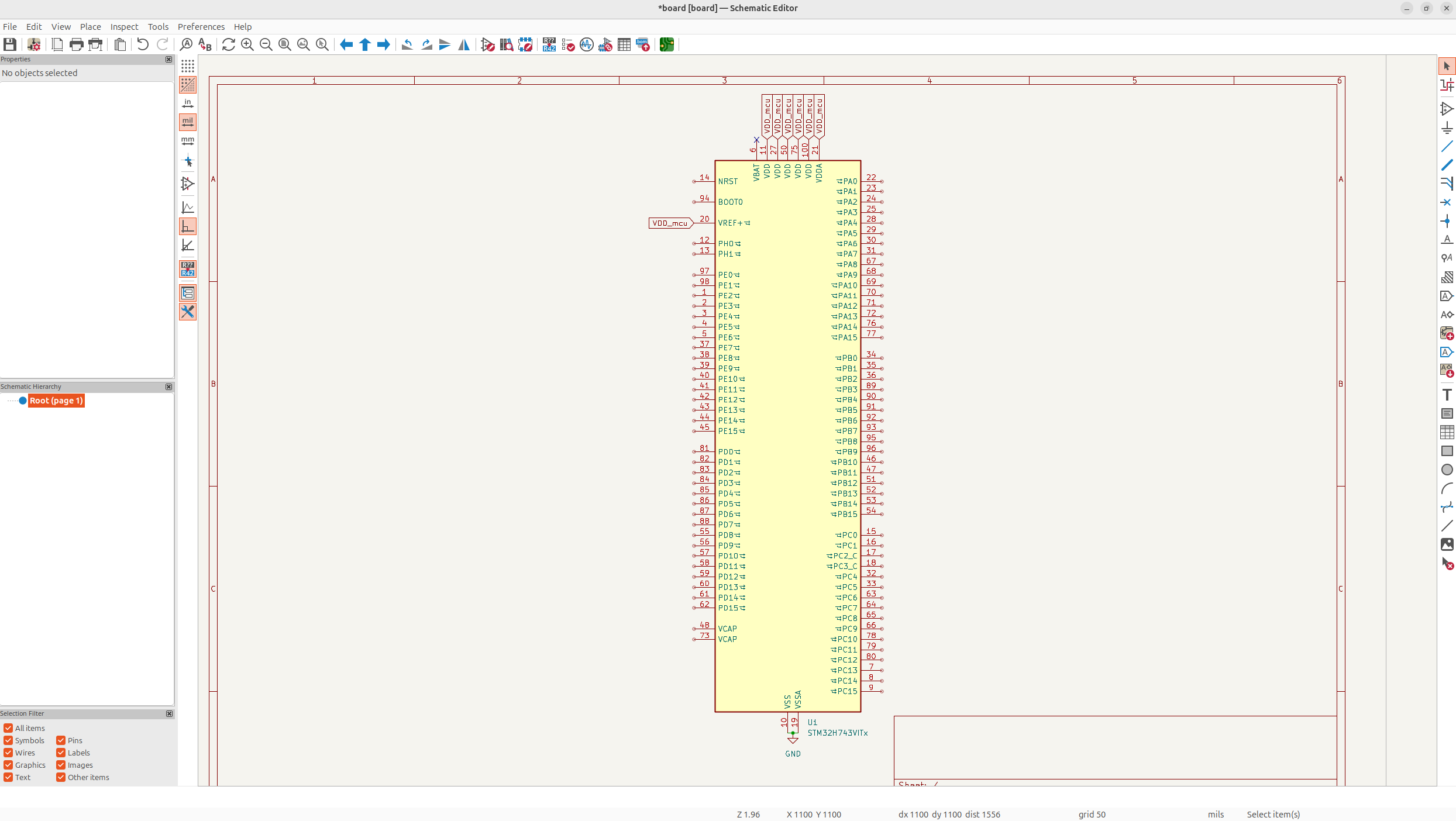
 Then of course, I'm going to connect all the simple pins like VDD and GND:
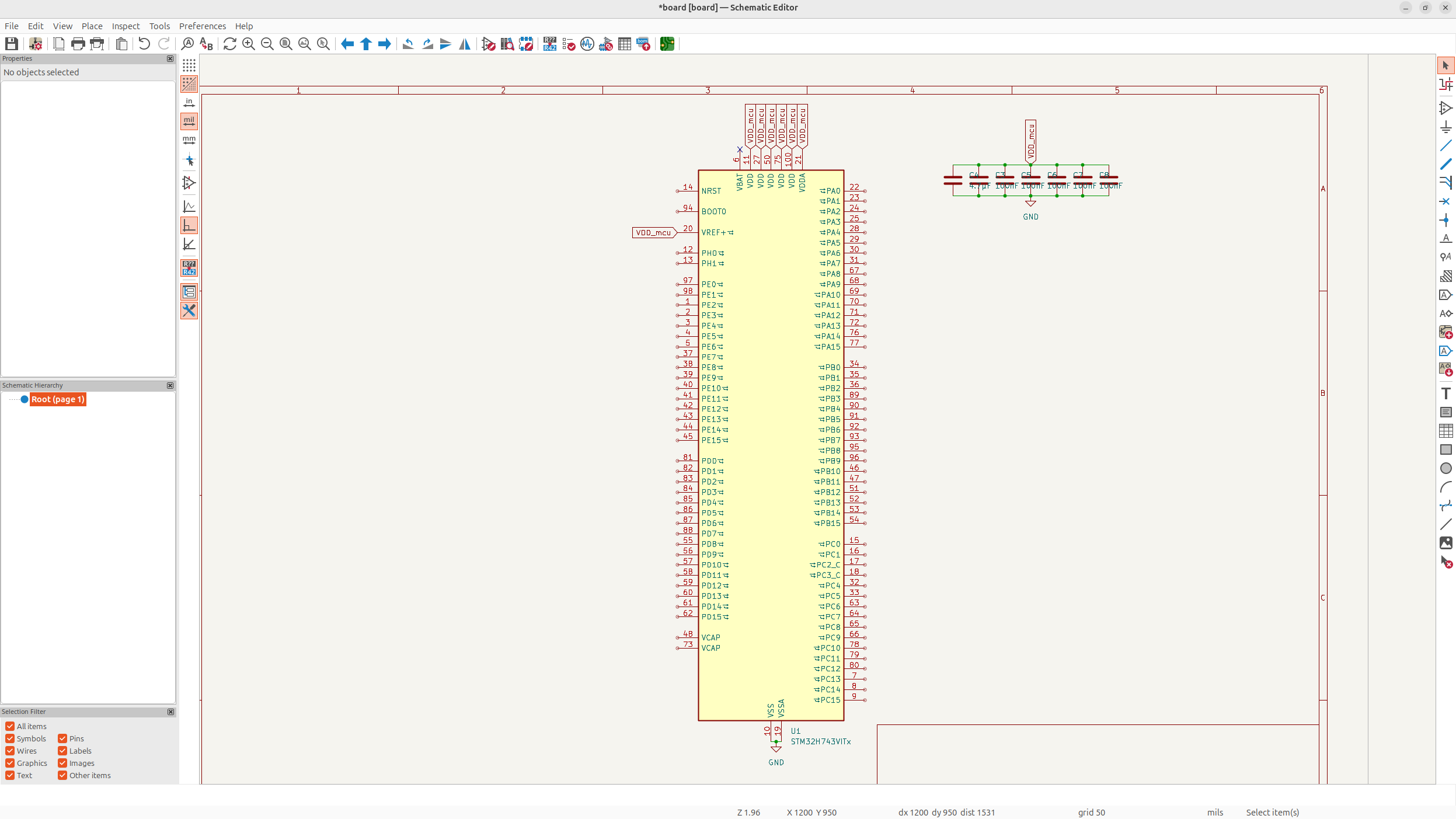
 Next, each VDD needs a decoupling capacitor, and then a larger one for VDDA and VSSA:
 Keep in mind, while I'm going through these fast, lots of these decisions take me hours, because I've never done this before and I have to re-iterate.
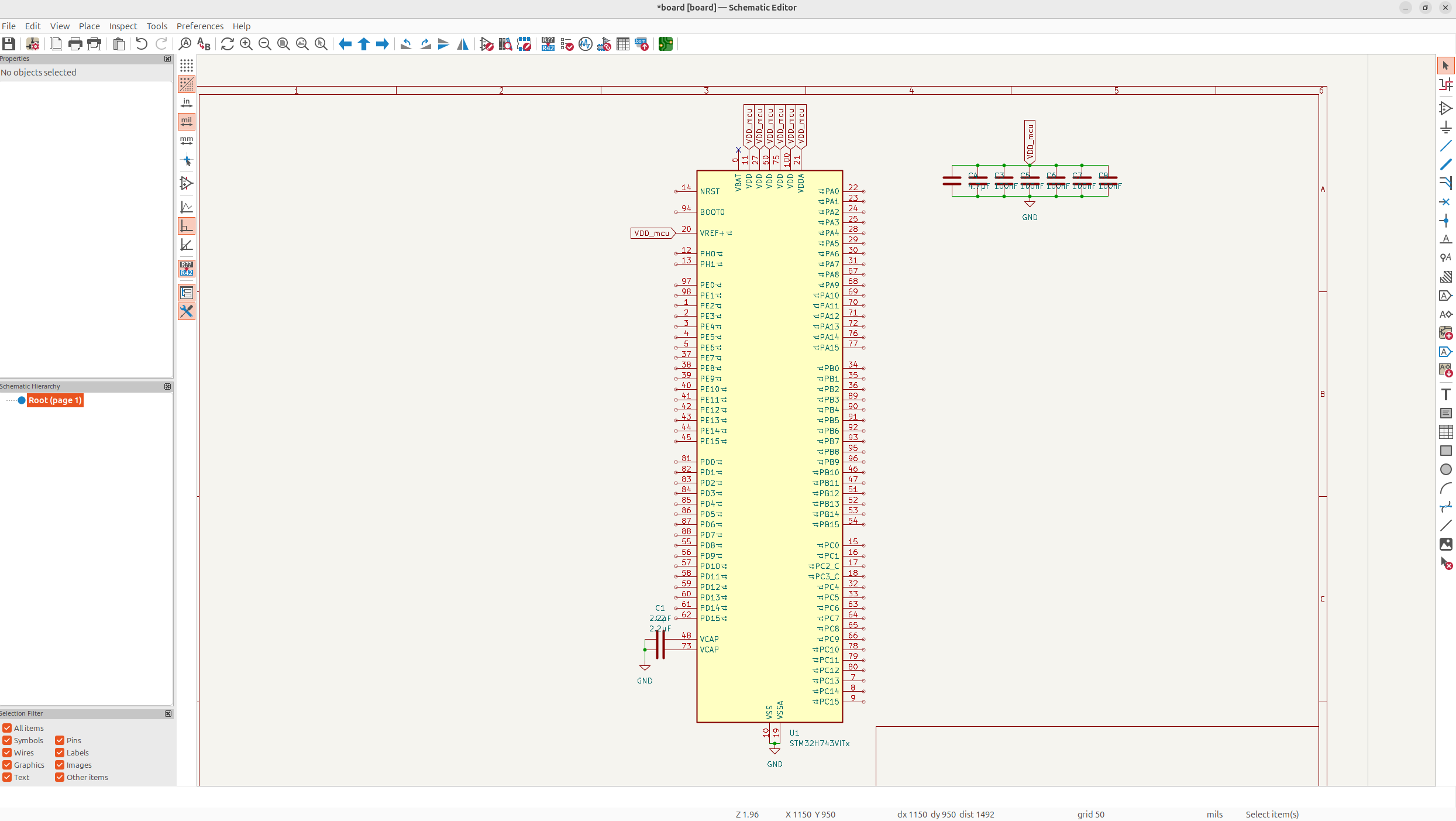
Anyways, next I forgot, but I need caps on VCAP so that the internal voltage of the chip is alright.
And then next, I'll add resetting and booting, which took me a really long time to figure out, but with some friends help, I got it down pretty good.
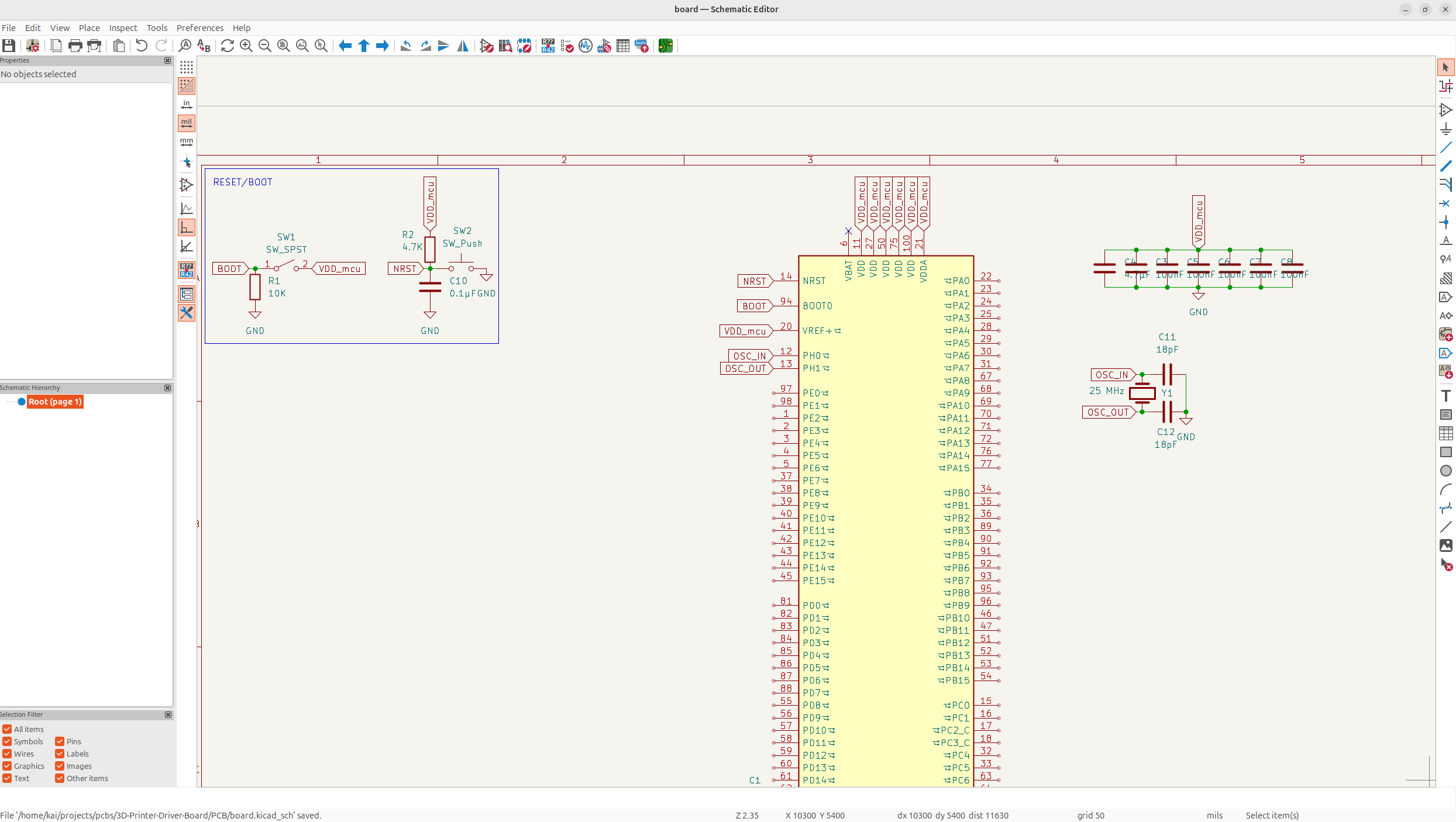
 And then after that, I need to added my main crystal in. I chose 25 MHz because it's better for USB and ethernet clock accuracy for some complex reason, but it does.
Day 2 - Finishing MCU Schematic - 10 Hours
I got quite a bit of work done on the MCU yesterday, but today, let's finish it off, and potentially we can get started on working on the motor drivers.
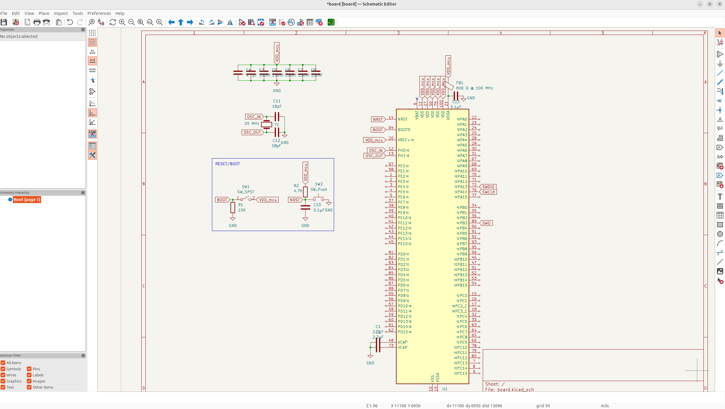
First of all, I added Ferrite beads to VDDA so it doesn't receive any noise from the standard power line:
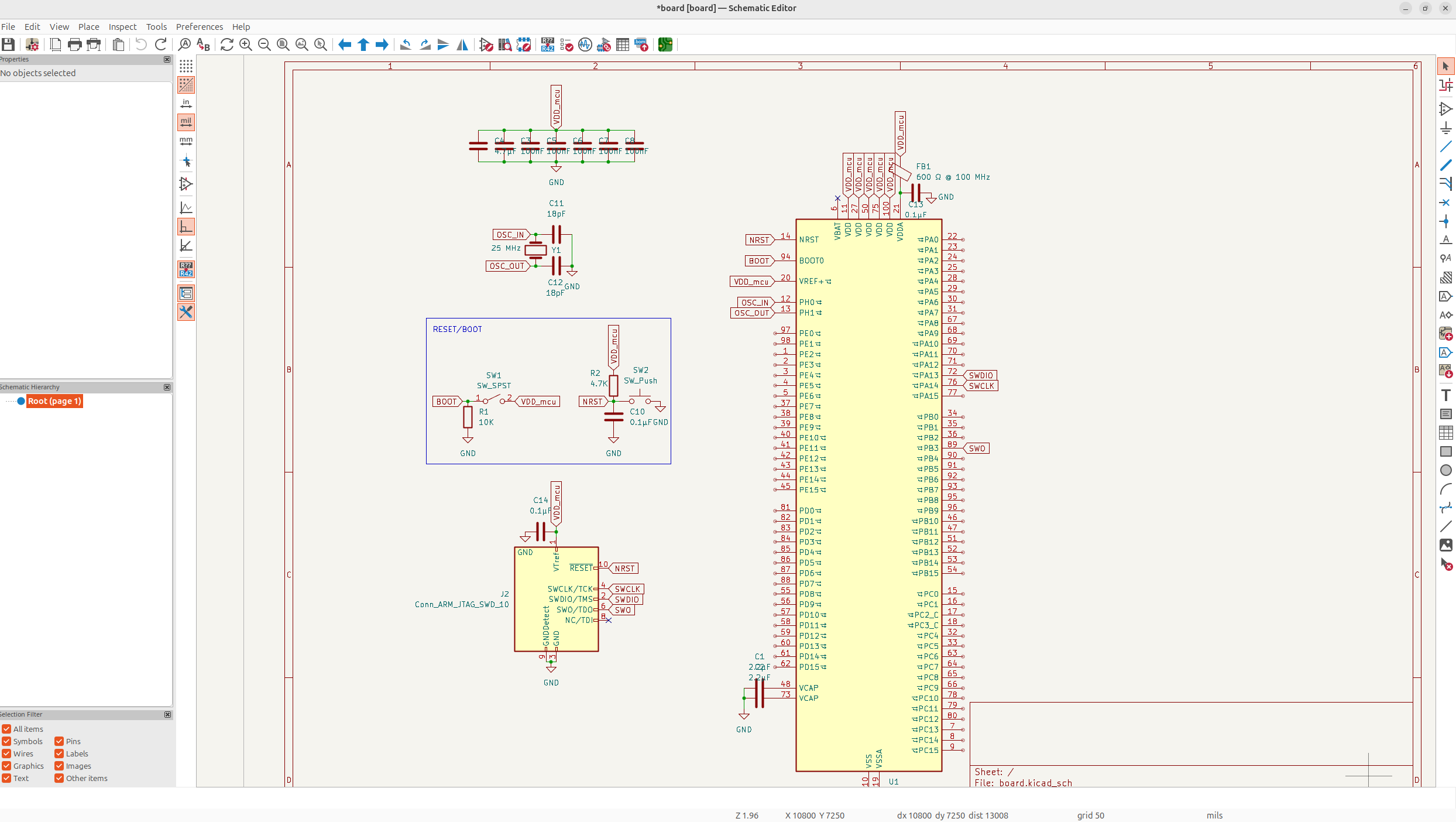
 After that, I implemented SWD header debugging so I could debug the programming and manually flash and stuff.
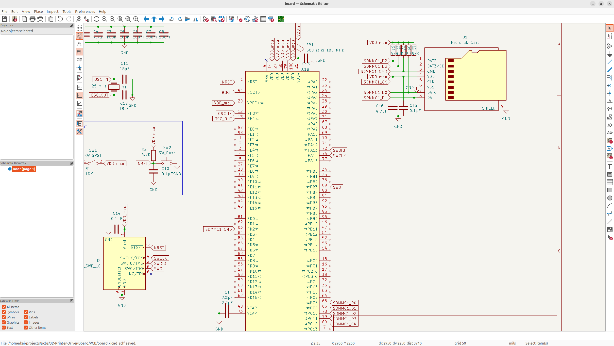
 Now there's some more things I need on the MCU, but I want to work on the SD Card and USB peripherals. First I'm going to put the SD Card in, because that one made a bit more sense to me, everything is basically data or power/GND and then you just put pull-ups on data's and pull-downs on powers.
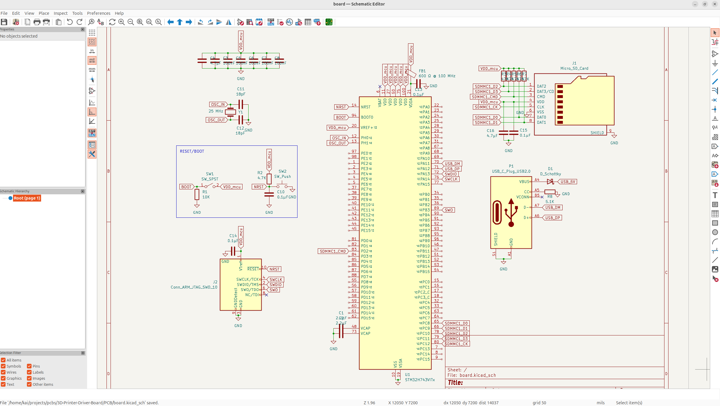
And now I just have to add the USB-C and CAN ports, I chose USB because it's pretty modern and there's also no harm in having CAN, especially because it's such a high quality board, I think enterprises will like it.
I'm also going to have it where when the USB-C is plugged in, it's going to power the board, but you can also power it with an external power supply, this is just really convenient for development.
The MCU is looking pretty sick now! Time to implement CAN in! But while researching whether to put CAN in or now, I found out that the TMC2209 doesn't actually support it, and instead I need UART. So I actually did finish implementing it, but now I just need to use UART instead so I'm not going to bother.
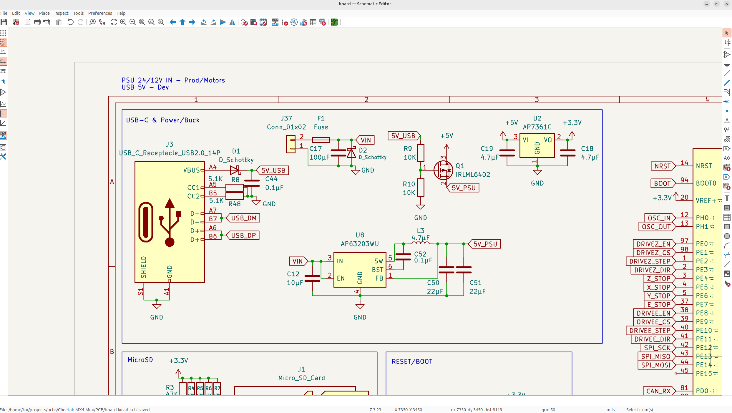
Something I neglected though, was adding in the PSU input for the board, so let's add that real quick. You'll notice the board is constantly being changed with some new formatting, just because everything is getting bigger too.
And now we have the PSU in the top corner.
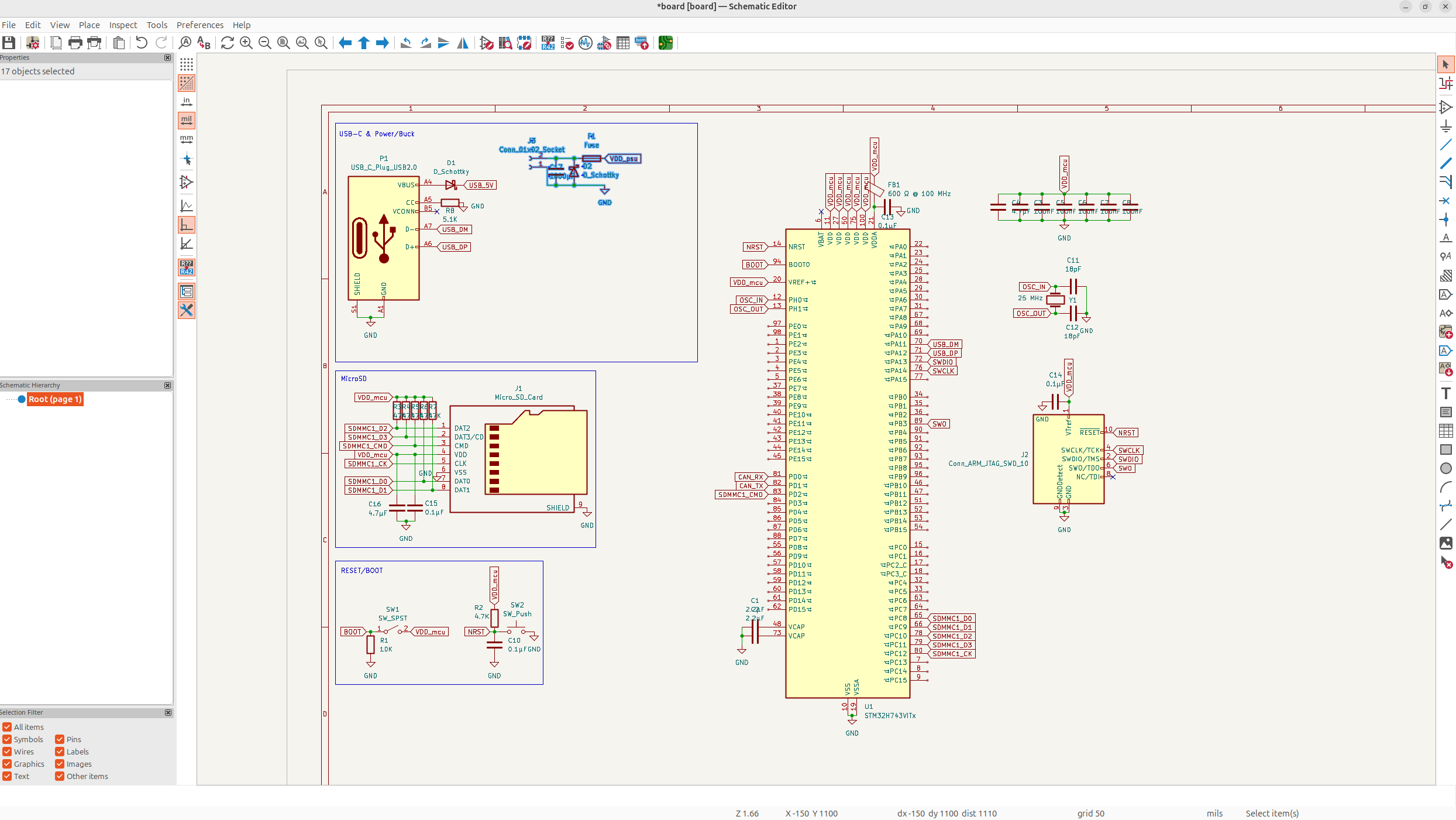 It might be a bit wrong, but I'll figure that out in a bit, for now, we need to convert the 12/24V down to 3.3V for the MCU.
It's a bit complicate to wire, but basically just steps down to 3V3, and then stabilizes and protects it using some capacitors and diodes, and then it needs some internal voltage too, which is what the FB pin is for.
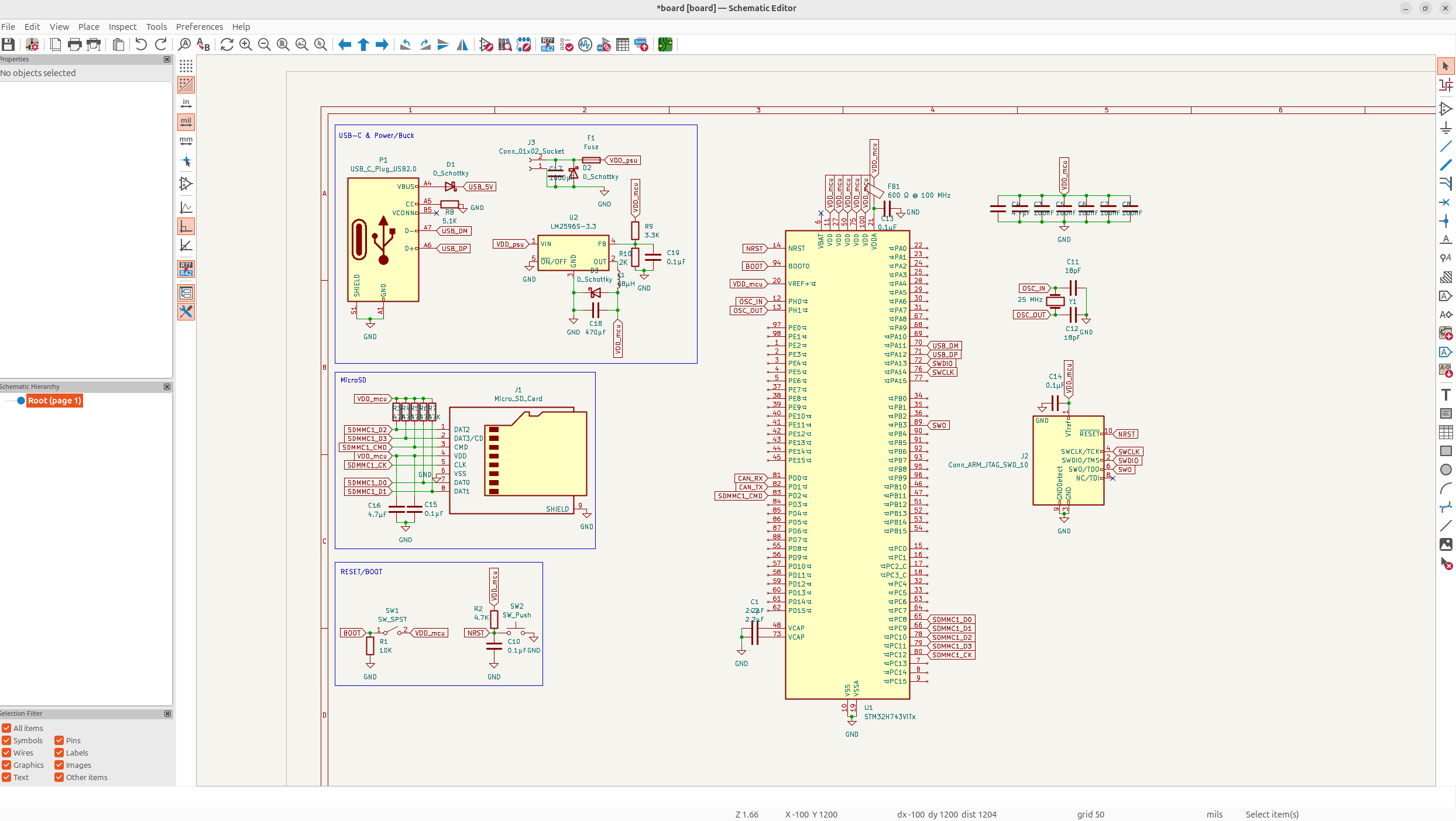
And just like that, we have a buck converter for the PSU! But I still kind of need to convert the 5V from the USB down to 3.3V for the MCU, so I might need to re-use the current buck converter if I can, or add another one...
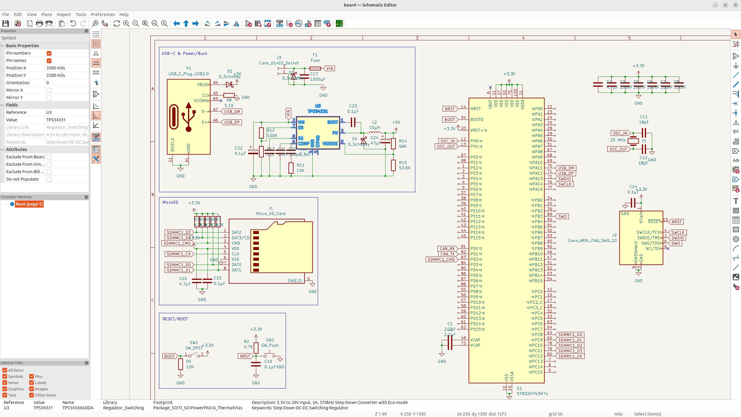
But anyways, after reaching out to some people, they suggest I use a different buck converter because of the bad switching frequency, and also convert to 5V instead of 3.3V and then use an LDO to get from a 5V rail to 3.3V. So after a bit research, I'm just going to use the TPS54331 chip.
So after an absurdly long time, I got the buck converter wired for 12/24V to 5V.
I know I don't journal everything I do with this schematic because there's so much stuff, but I'm constantly making iterations, so I also replaced all the new labels with power labels and re-organized some stuff.
Anyways, that's the majority of the MCU stuff wired now. I spent a really long time working on this stuff today, and I got a lot done!
Day 3 - Power and Drivers - 10 Hours
Today was all about finishing the power schematic, and adding in the stepper drivers and maybe some other things into the schematic.
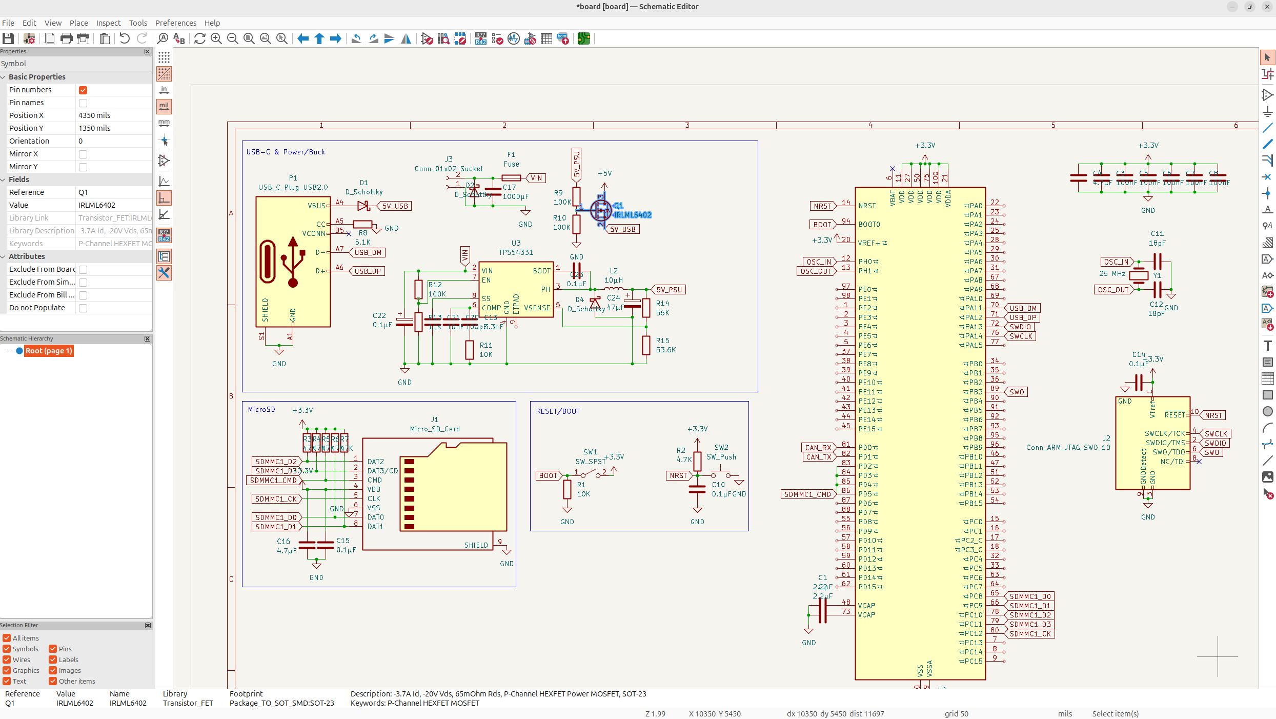
So first things first, I need to have a common 5V rail. You see, both the USB and the PSU with the buck converter, are going to output 5V, but they can't both output them at once, so I need to output only one of them if they're both on. I'm going to prioritize the PSU, because the PSU also provides a 12/24V power, so it's going to be preferential if they're both connected.
I'll use a simple P-Mosfet circuit:
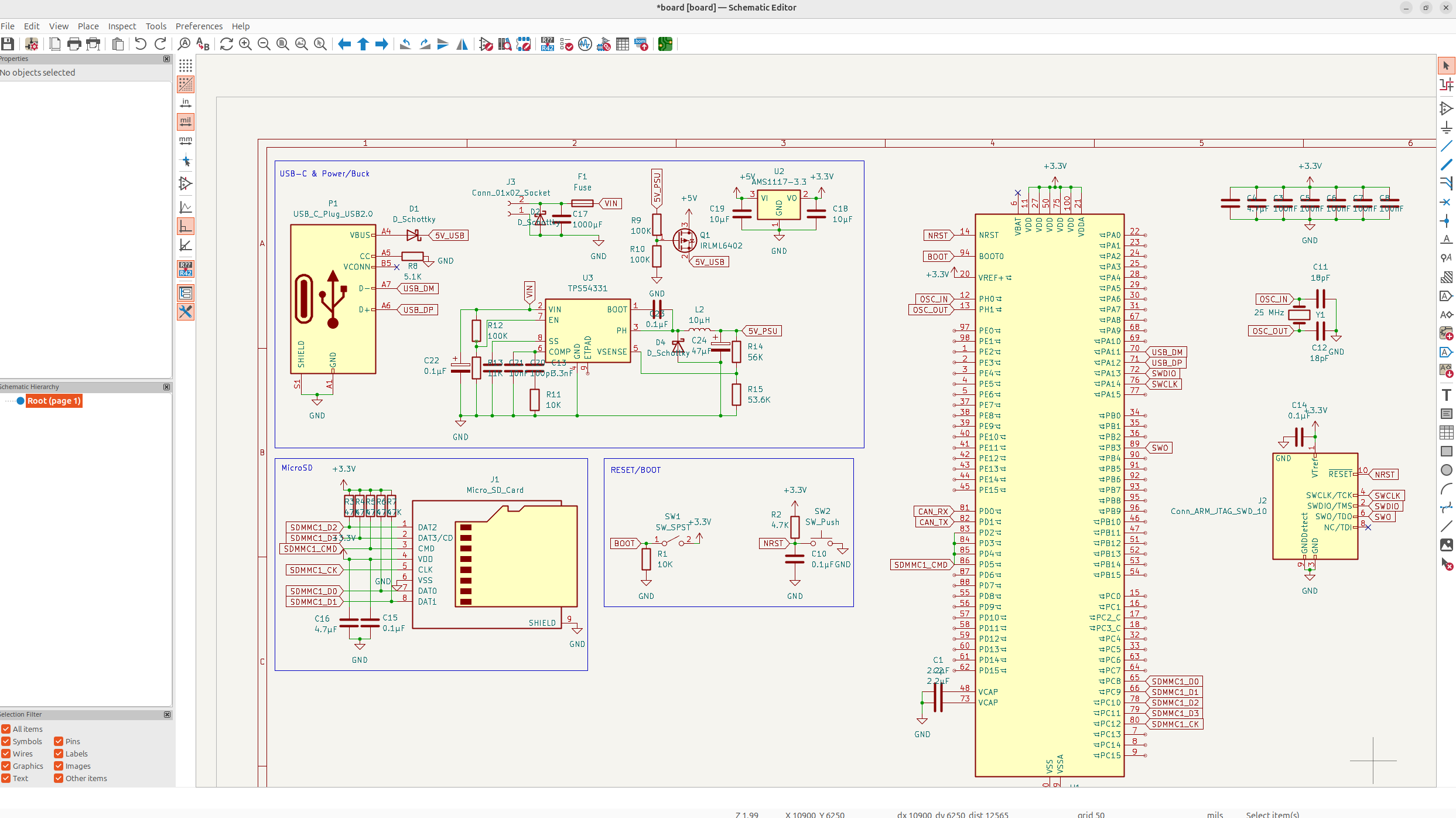
And then I need to add a linear regulator/LDO to step down the 5V to 3.3V for the MCU and some other operations. You see, I need the 12/24V for the steppers, the 5V rail for some fan gate and other operations, and then the 3.3V for the MCU and stuff, so it's important that I have all of these rails separate. I'm going to use the same LDO as the Manta M4P, the AMS1117 and then of course decouple it to stabilize the voltage.
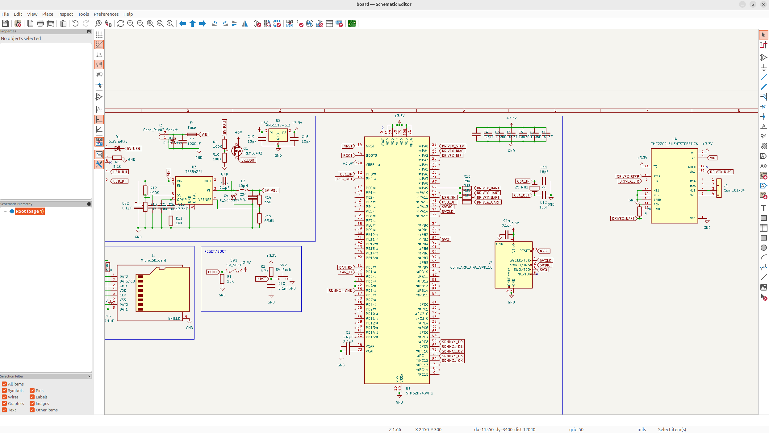
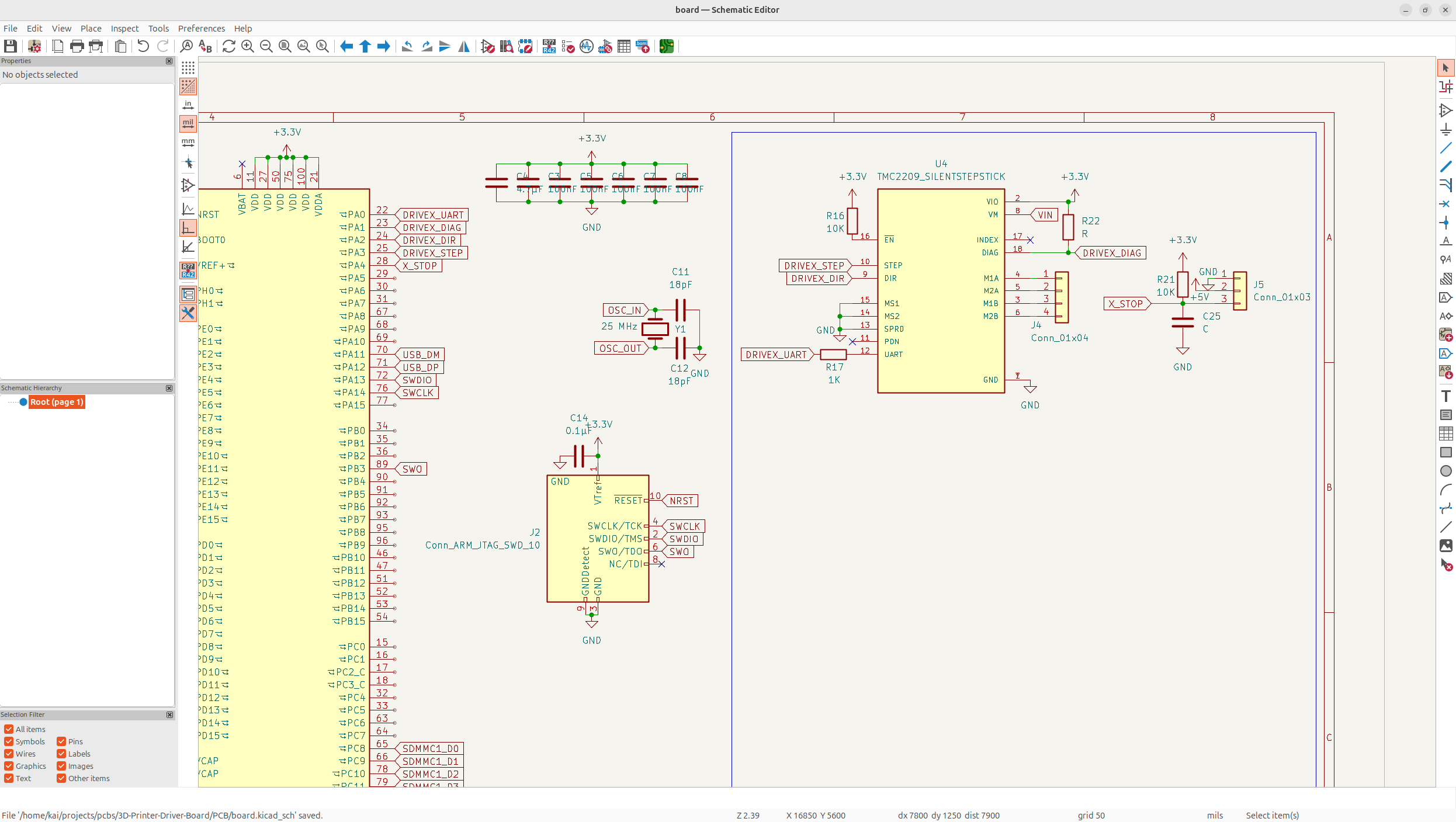
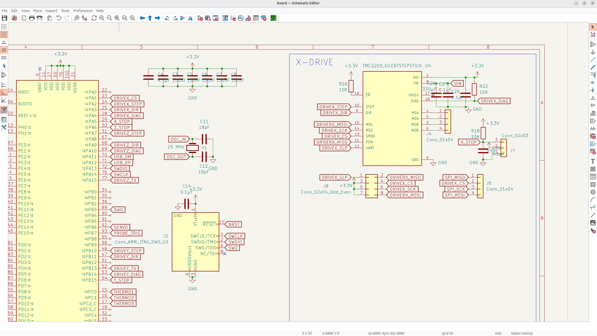
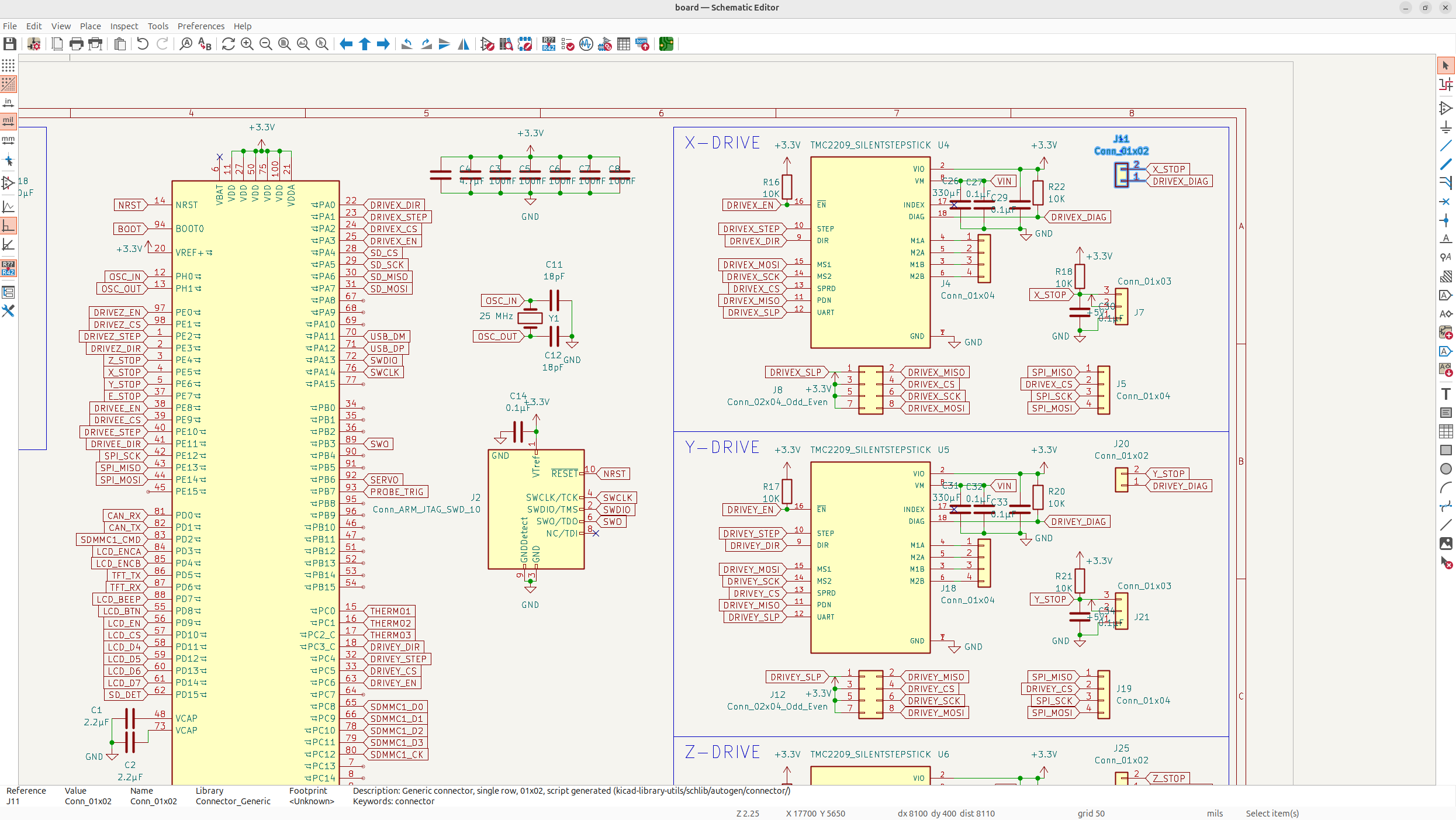
Now... we can finally get to working on the stepper drivers! The MCU and power is finished so let's add the X driver, I'm going with stepstick, because I like how easy it is to assemble and it has a bunch of extra features which are nice, and it looks sick on boards instead of using an onboard chip.
So let's add the first motor driver... it's a bit tough to wire, but I think this should be good. I'm using UART to control everything and then I expose it to a 4 pin connector for the steppers.
Now I'm going to add the endstop pins... I want to be able to switch between sensorless and endstop homing, so I'm going to include both of them, just as separate GPIO's. The Manta M4P does a jumper switch approach instead, but I'm not low on GPIO's, so I feel like controlling this in firmware is more convenient.
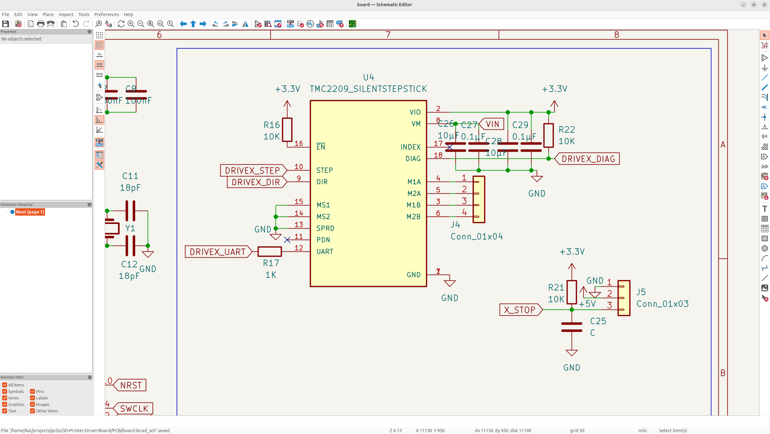
While adding the endstops, I also fixed the wiring for the TMC2209 silent step stick, because I was basically wiring it for the IC instead of the module, and I also added caps and pullups/pulldowns and whatnot.
And then I kind of forgot to add decoupling caps on the power pins so here:
And then after that, I looked into it a bit more, and I messed up the single line UART, you need to converge both the RX and TX UART pins to one line, but I was just using one IO.
After that, I planned out all the UART pins on the MCU so I didn't use them up accidently.
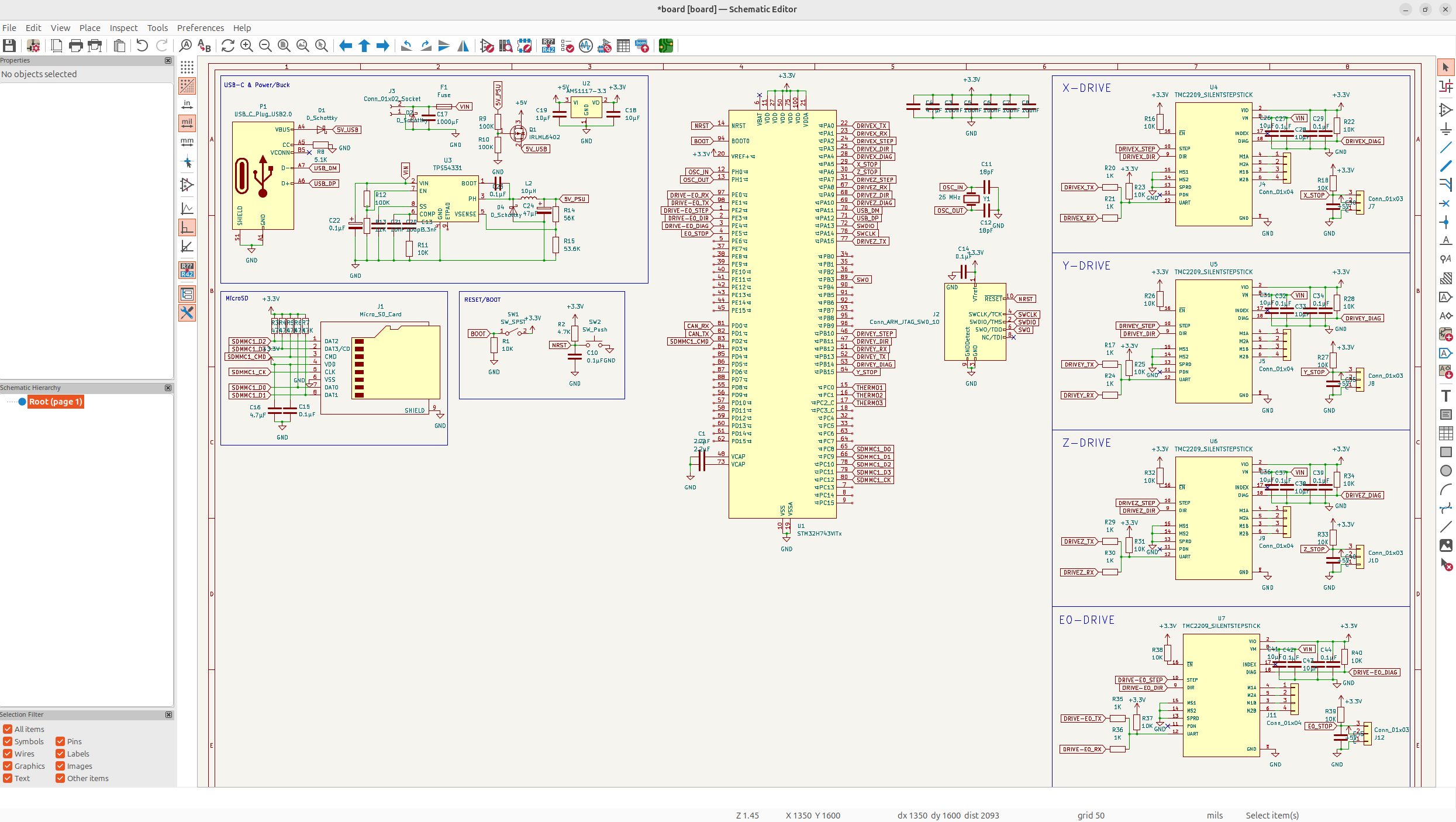
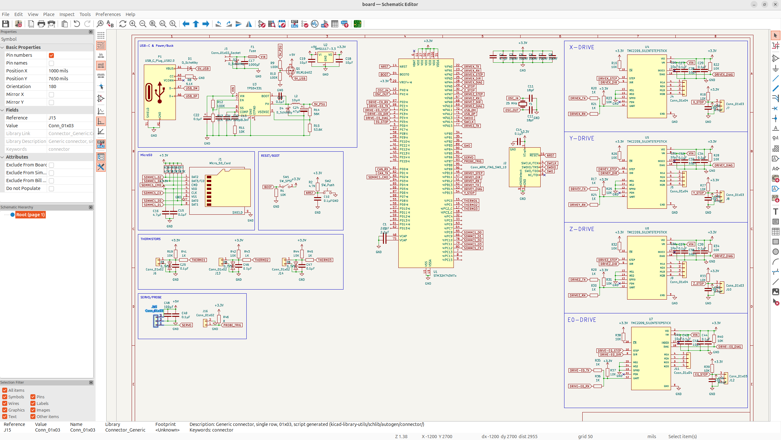
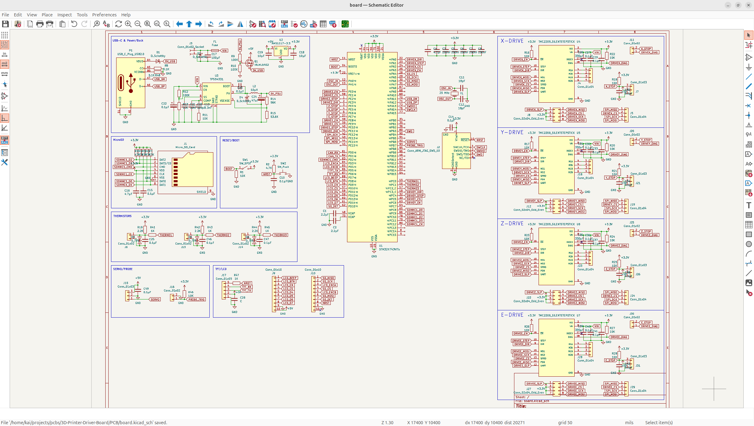
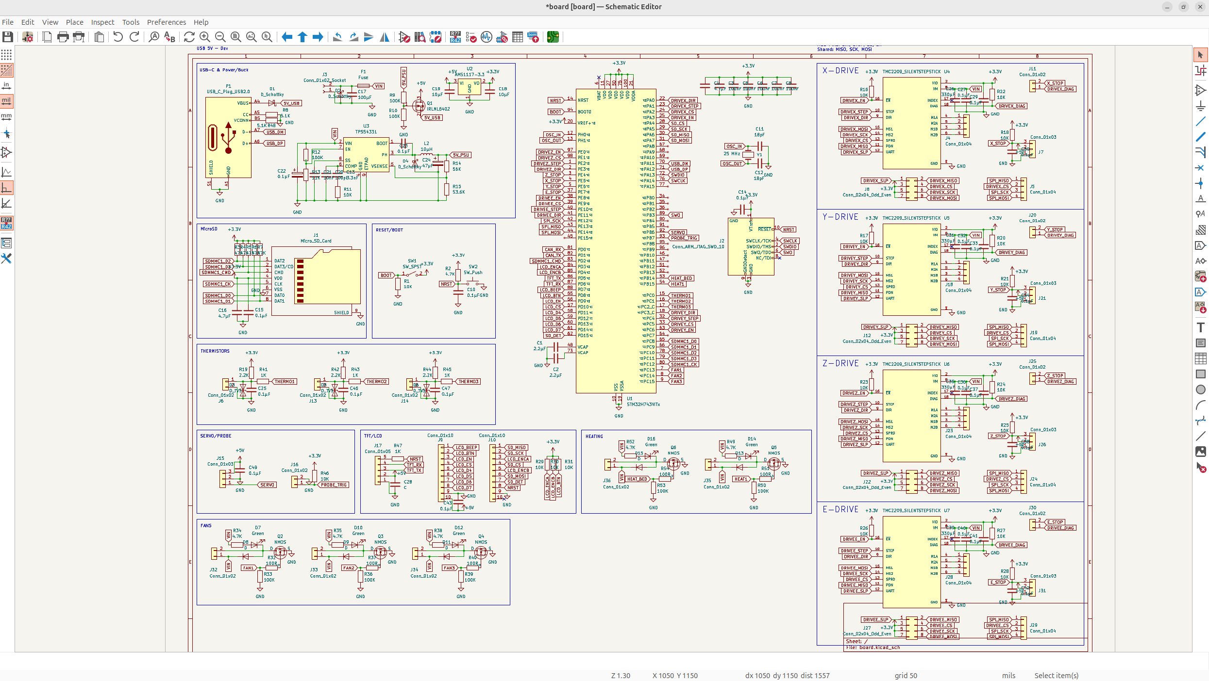
Now, I'm like 85% confident that the schematic for the motor driver is functional, so I'm confident enough to clean up the schematic, and add all 4 drivers in (x, y, z, e0).
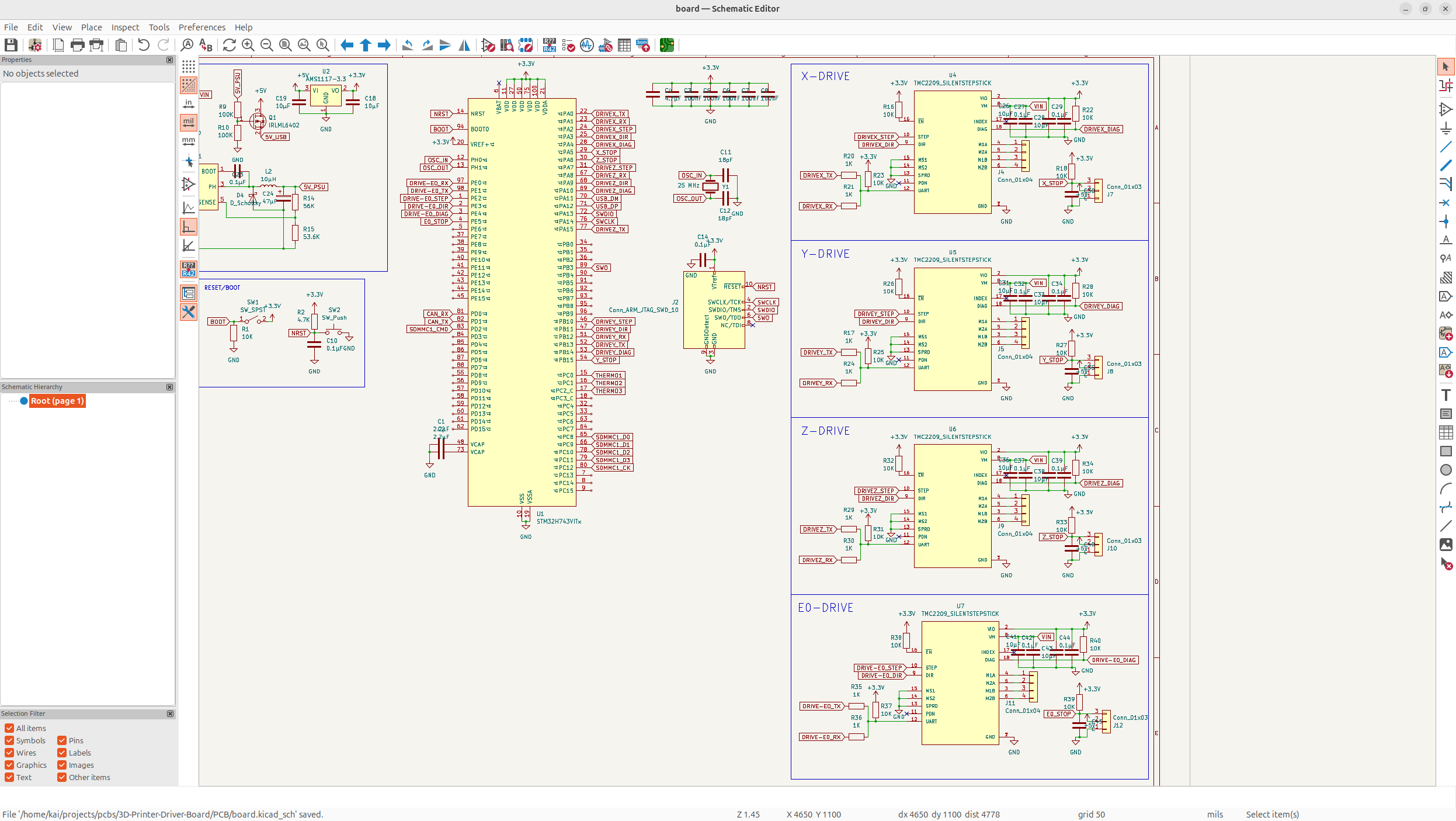
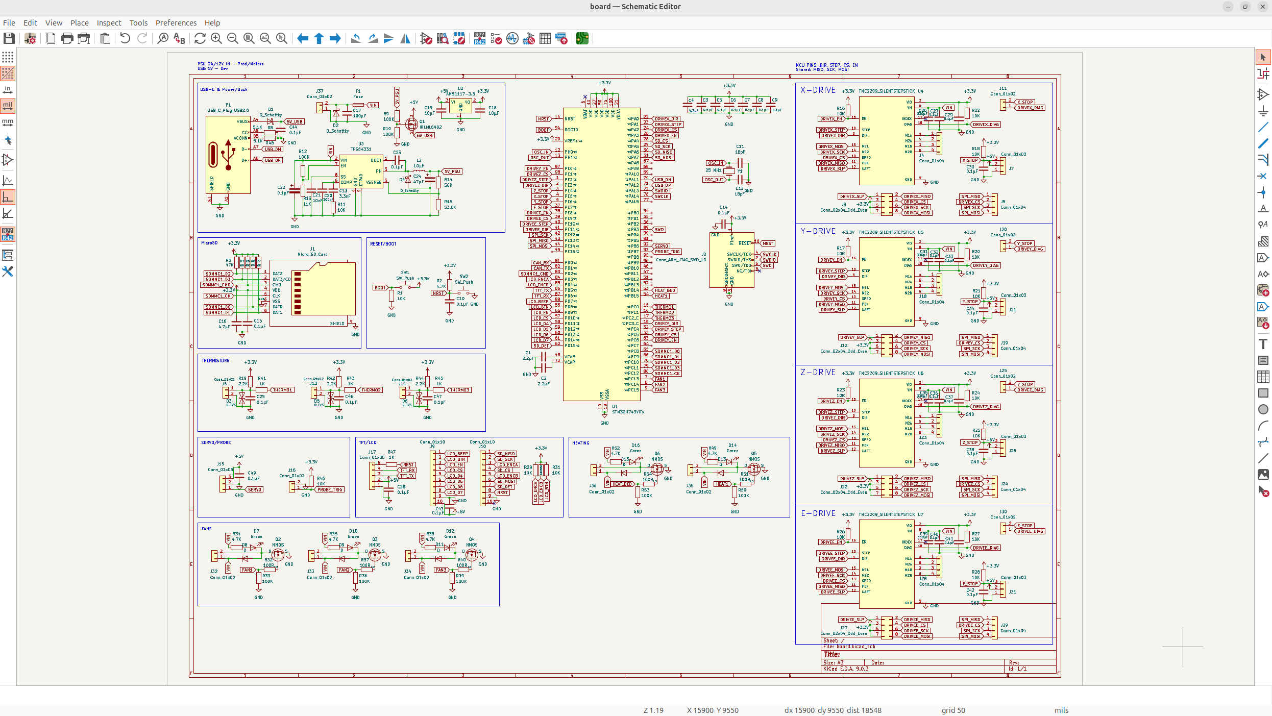
Now the schematic is looking INSANELY cool.
Now this day actually took me a really long time, because the motor drivers kept on having to be re-iterated on, and the parts were pretty complicated. At least I finally have the main part of the board on, so I can kind of get to adding features I want.
Day 4 - Funtime :D - 10 Hours
Today was all about adding cool features I want on the board like fans, thermistors, etc.
All the wiring should be easier from here on out happily, but I still need to be wary about protection and stuff.
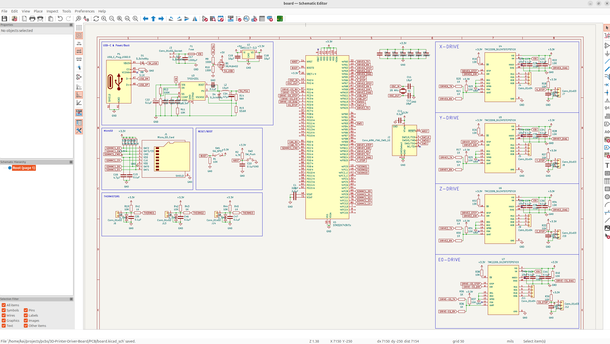
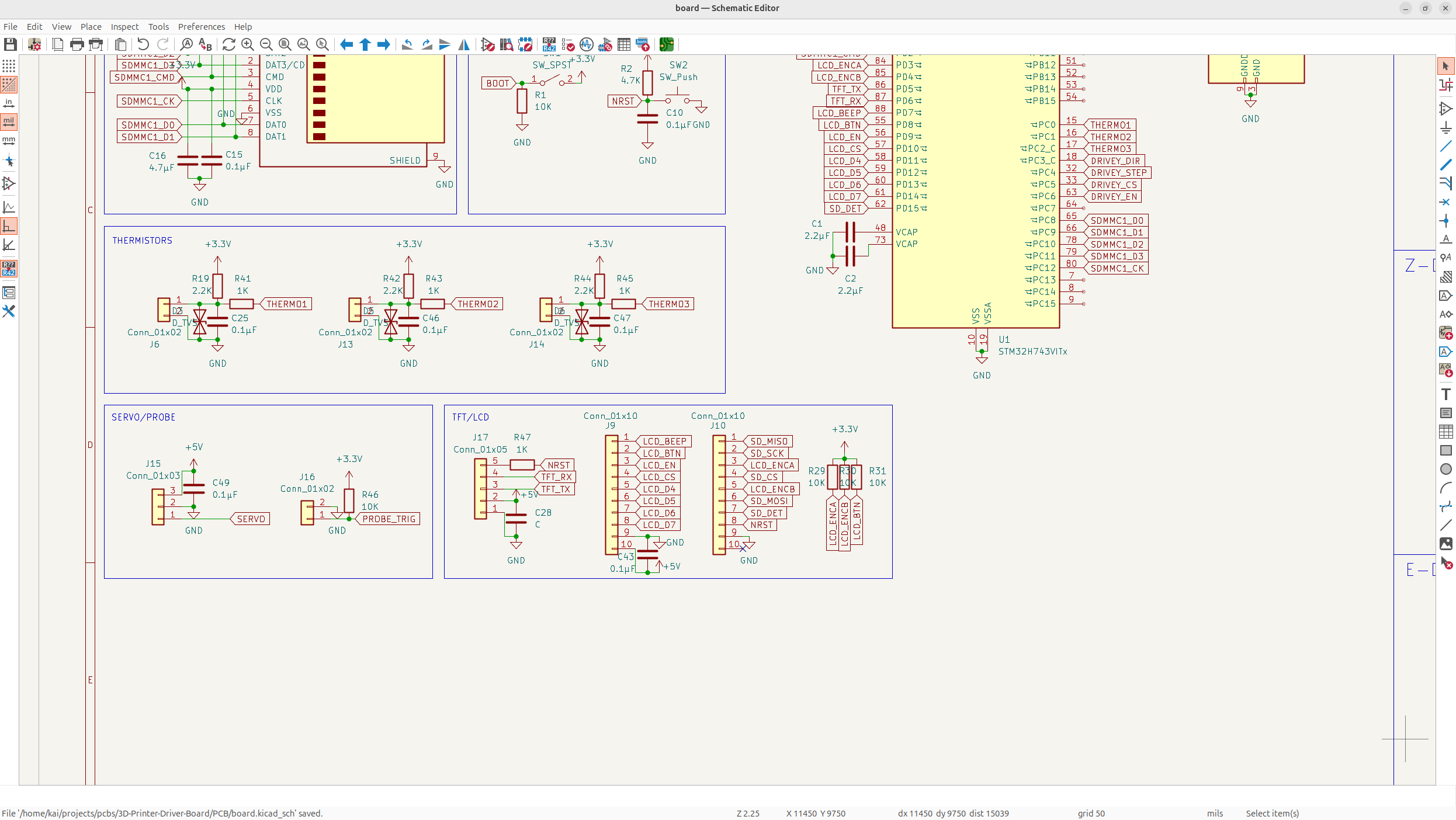
So first thing I'm going to add to the board, is the thermistors. I've decided on going with 3 thermistors because if people want more, they can always add an I2C bus, but most people aren't using more than 3. The connector is just GND with an IO pin, with some pullups and a protection for transient voltage spikes/surges.
Now I can just multiply this for the 3 thermistors I want:
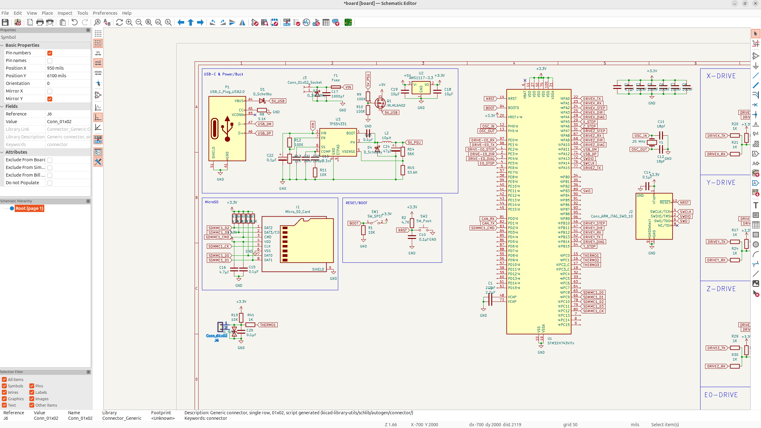
Next, I'm going to add a connector for a servo port, because people sometimes like to have a servo for things like a bed leveler or a filament changer.
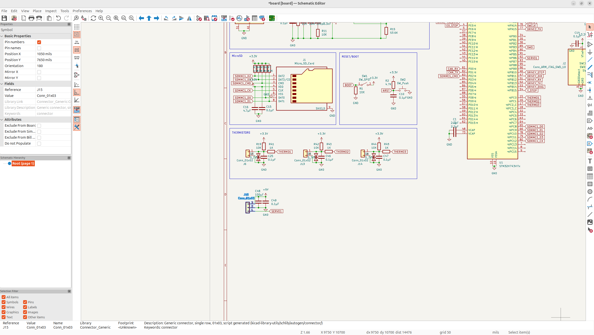
And then I can do this cool thing, where I add an inductive probe connector, but this also functions as a BLTouch port using both the servo port AND this inductive probe connector, so it's like a triple function.
Now I need to implement SPI on my stepsticks. Now this took me nearly 5 hours to figure out and implement, and I still think it's a bit wrong, but it's the right idea. Basically lots of TMC drivers only support SPI instead of UART, so you need to support both and be able to switch between them.
And I'm just going to end off there because that took me so long to understand and figure out.
Day 5 - Touch-ups and Features - 6 Hours
Now, I've figured out the core board, and I can add some more features like TFT and LCD screens and some other things.
So first I implemented a TFT display using UART:
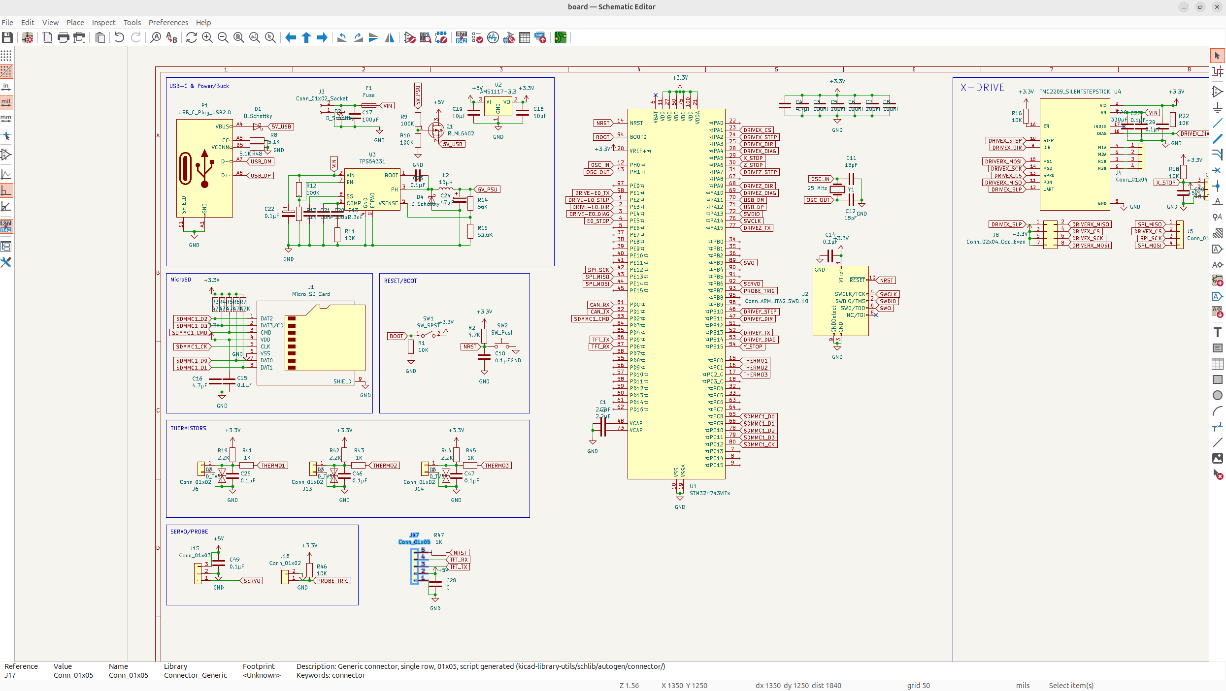
and next, I wanted to be able to support LCD. I want to support SD cards too, so I need a connector for SD card LCD and normal parallel LCD displays, so I have to make 2 like so:
It took a really long time to figure out which pins needed peripherals and fitting them onto the MCU, but I got it down pretty nicely:
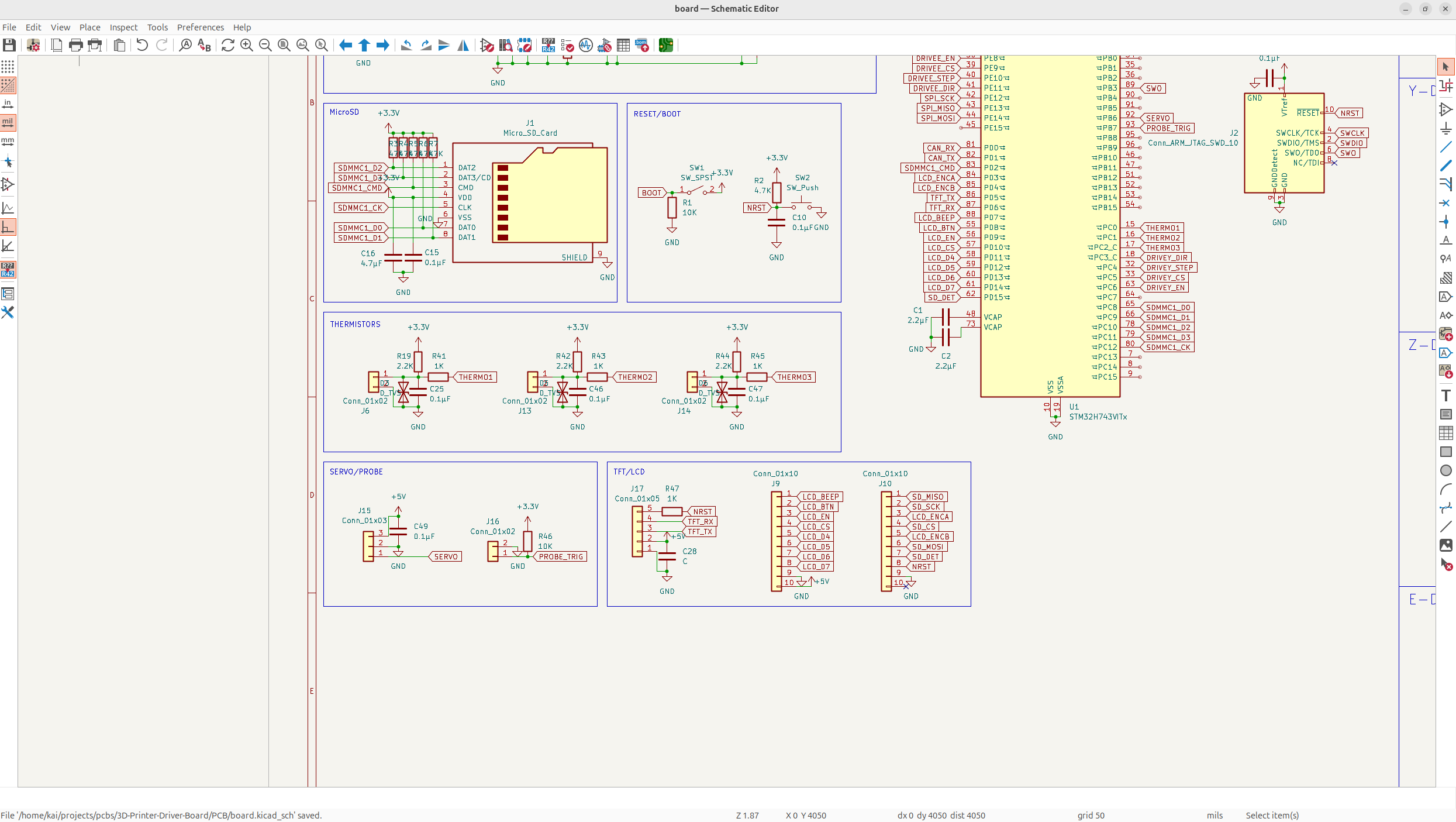
And now, I needed to refine my drivers even more. I wanted to add a jumper so that I could toggle between endstop and sensorless homing, so I only needed 1 label which would free up my MCU a bit better. I also needed to add EN apparently, so I wired that in too and cleaned up my SPI.
Not just that, but I also added all the drivers, all this took me a pretty long time, but I'm just summing it up:
This is the new connector that can toggle homing:
It's pretty simple, it just bridges the endstop GPIO, and then you just configure it in software to disable the endstop.
I've been constantly iterating and stuff while doing this, so all of this is taking much longer then how I'm putting it...
Anyways, now I have a feeling I might need some pullups/pulldowns in some places? But aside from that, that's pretty much all the main features on the board I was aiming for, which is amazing!
And of course I was right, I was missing some pullups on the LCD displays, so I added that alongside a small decoupling cap:
Day 6 - Finishing the Schematic - 10 Hours
Now, the only thing I really need on my board is the fan ports and potentially some protection circuits/fine tuning?
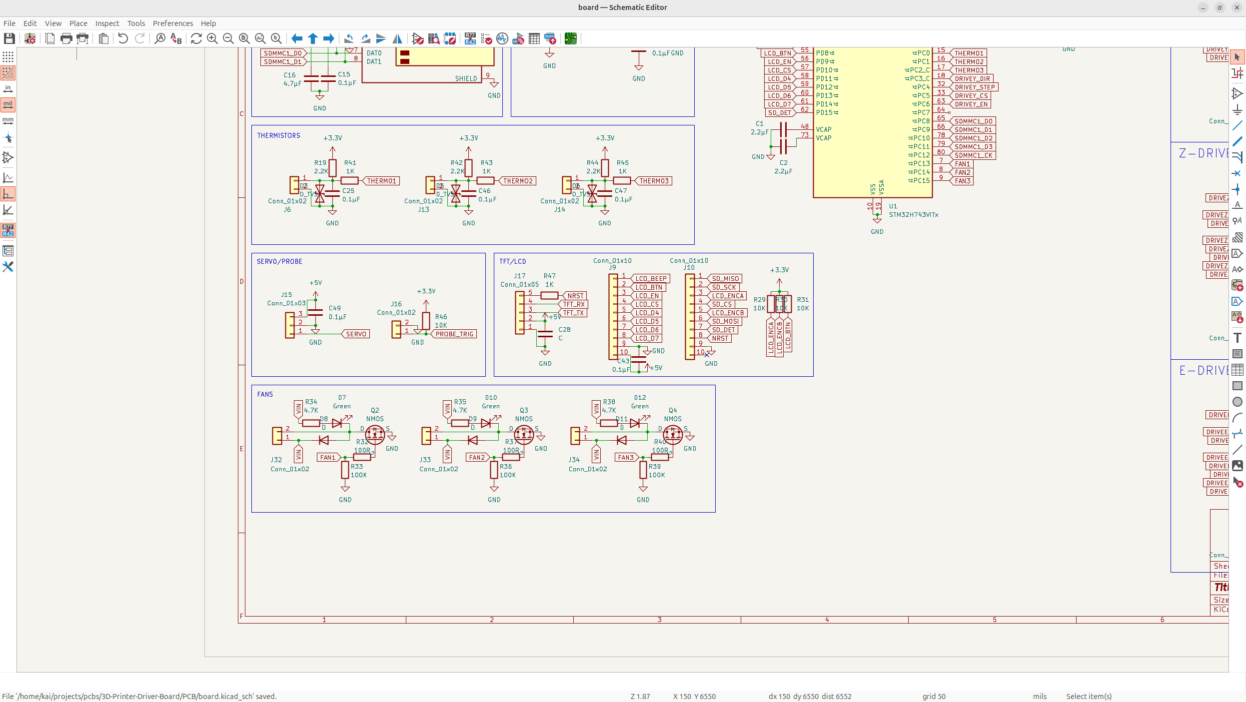
So now let's add in the fan connector... I want to support PWM control which allows fine control of the fan speed and whatnot, so I'll probably need a larger connector.
Anyways, PWM is a bit chonky, so instead I'm going to use this cool switching circuit that basically like quickly turns the fans on and off to kind of replicate PWM but worse but it's smaller which I kind of like and I don't really need precision for a 3D printer.
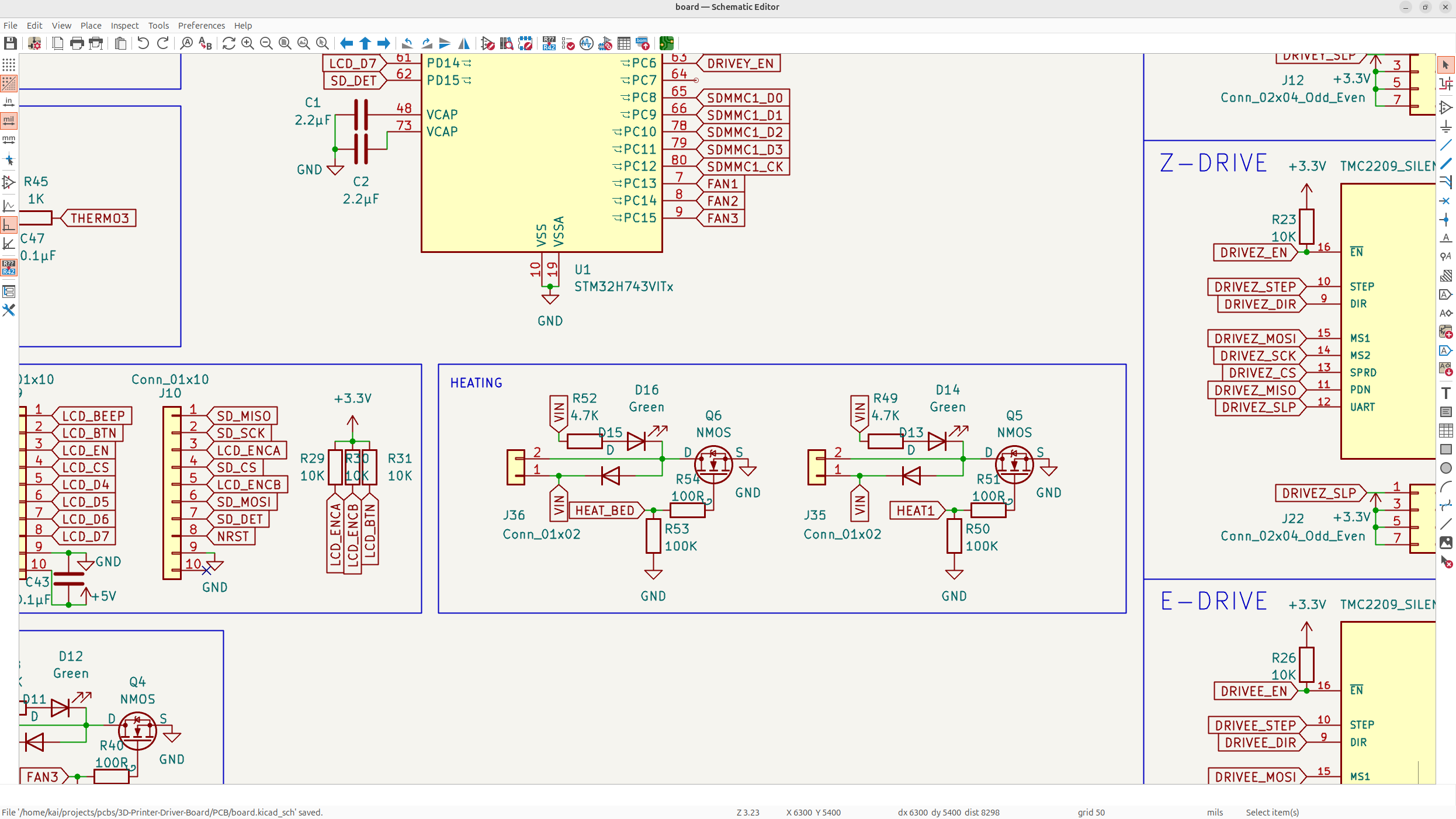
And then, after that I just added the basic wiring for the heating elements. It's the same as the fans, but the heating elements draw a LOT more current, so I might need to wire them a bit differently than what I currently have? But I'm not too sure...
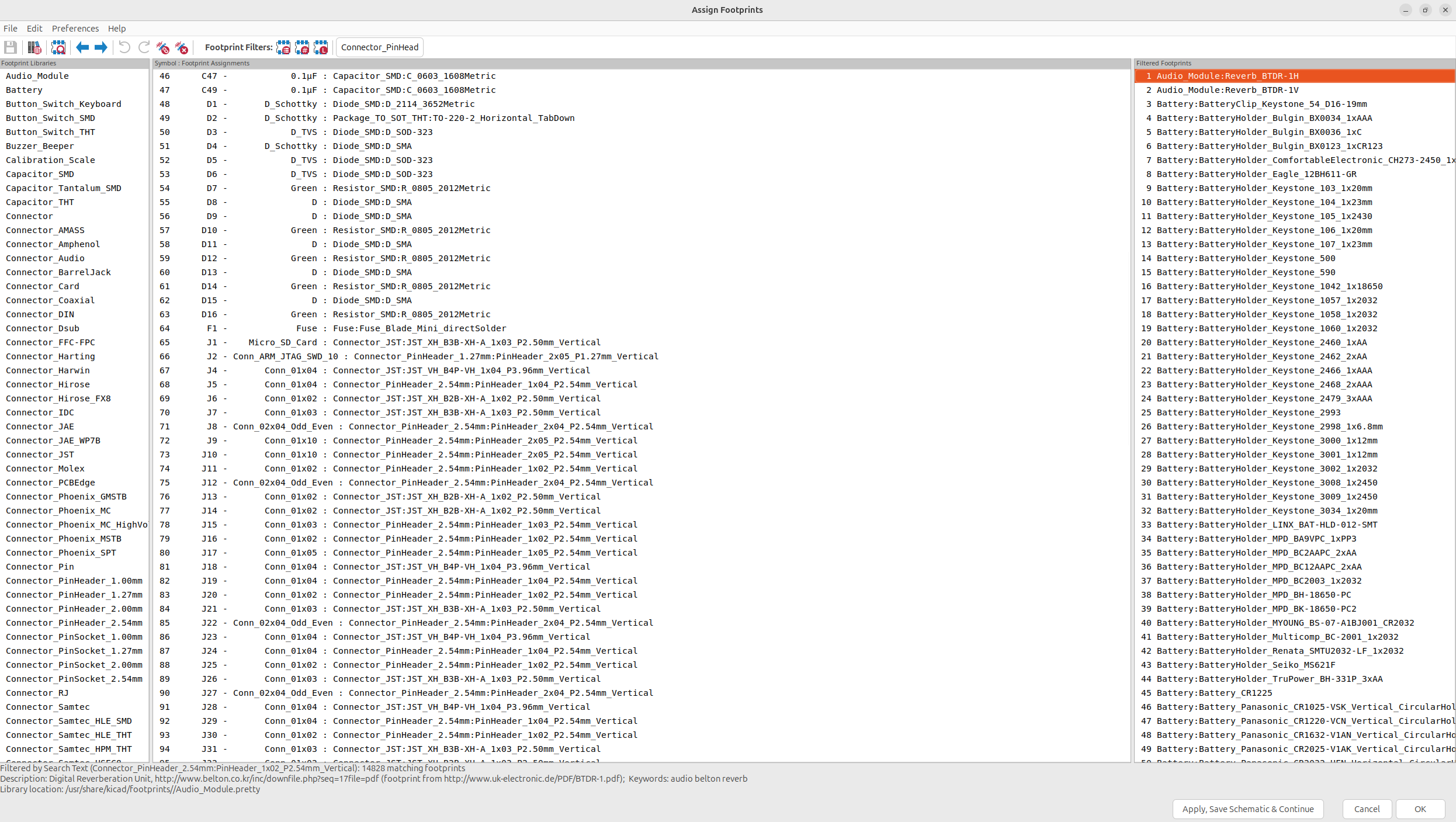
But anyways, now I could finally work on adding footprints to every single part. This took me about 3-4 hours, but I got every single one except the motor stepsticks. Here's the basic protocol I got it down too: - Small (0.1uF) decoupling caps get 0603 capacitor footprints - Medium (>1uF) decoupling caps get 0805 footprints - Larger ones (>10uF) get electrolytic capacitors varying in size - Resistors with large current get 0805 footprints - Resistors with small amounts of current get 0603
And then everything else was pretty much fully custom. The different connectors took a bit because you have to figure out the exact connector each thing is, and you don't really want to mess it up:
Now I just needed to add the footprint for the TMC stepsticks, which I think need to be fully custom, but I'll see when I research a bit more.
The TMC stepsticks took about an hour and a half, but I got a pretty nice footprint, and the tolerances are only like ± 0.015 mm which is nice.
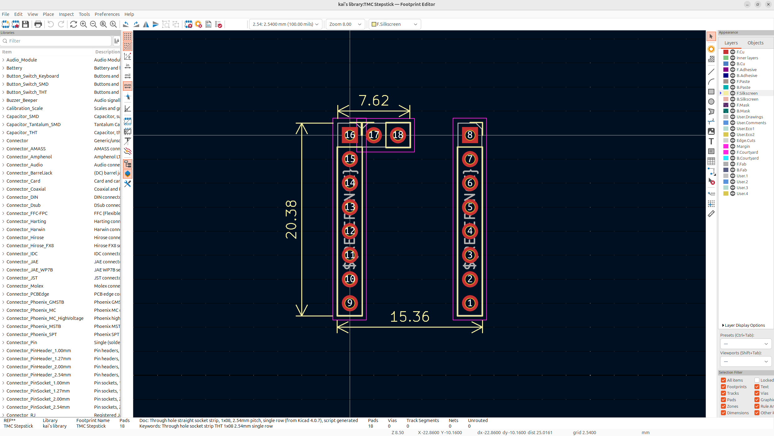
Now I can just add this footprint in, and my schematic will be finished!!! I also fixed up some other footprints to handle some of the crazier loads, but this schematic looks beautiful!
And then finally, I had to add the footprints for the displays... AND EVERYTHING IS FINALLY DONE!
Day 7 - The PCB - 10 Hours
Now today was about starting the PCB! I imported all the parts into Kicad but then noticed that lots of the parts weren't right. Specifically connectors and the crystal. The crystal had the wrong pinout and the LCD connectors were wrong.
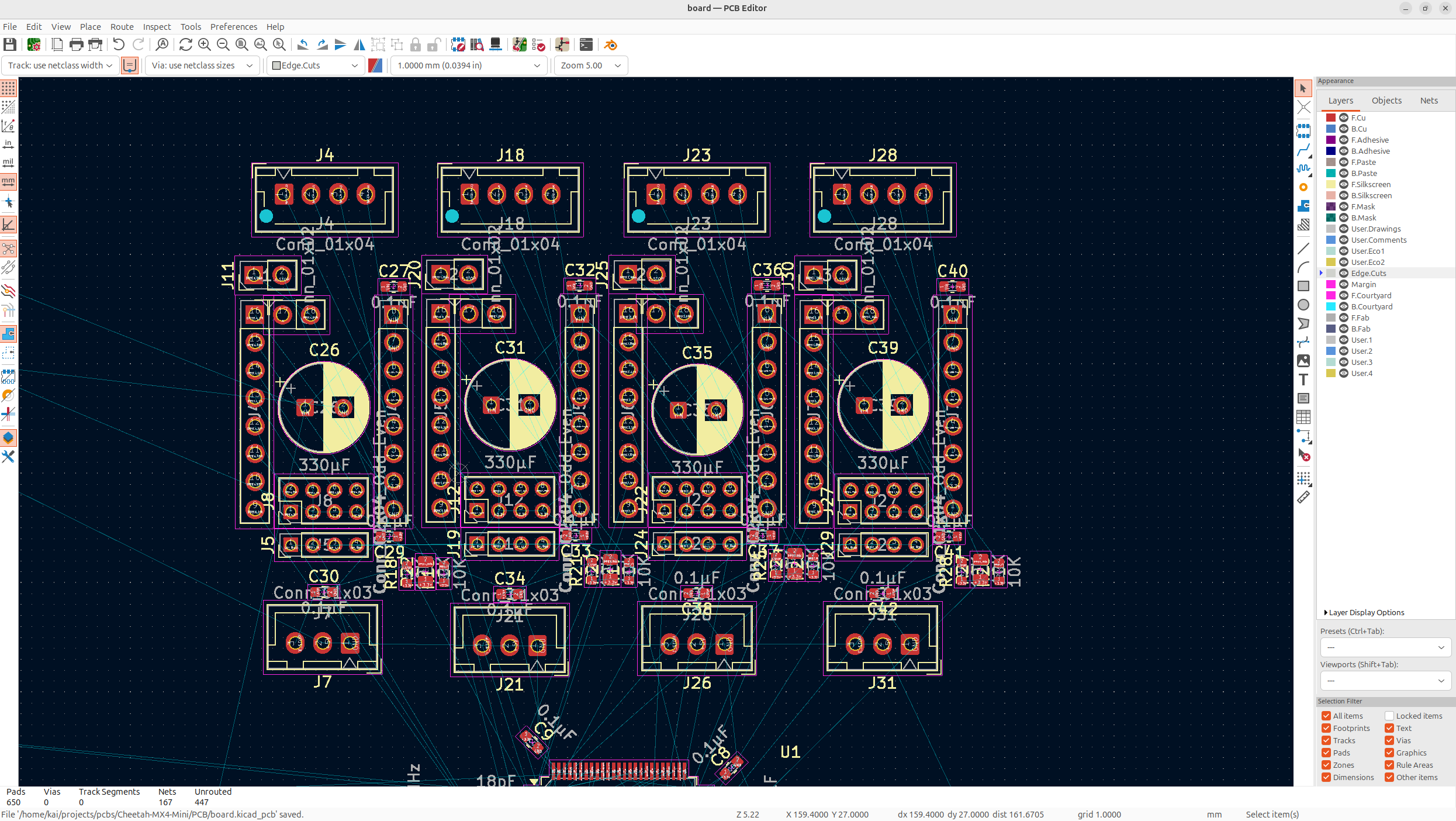
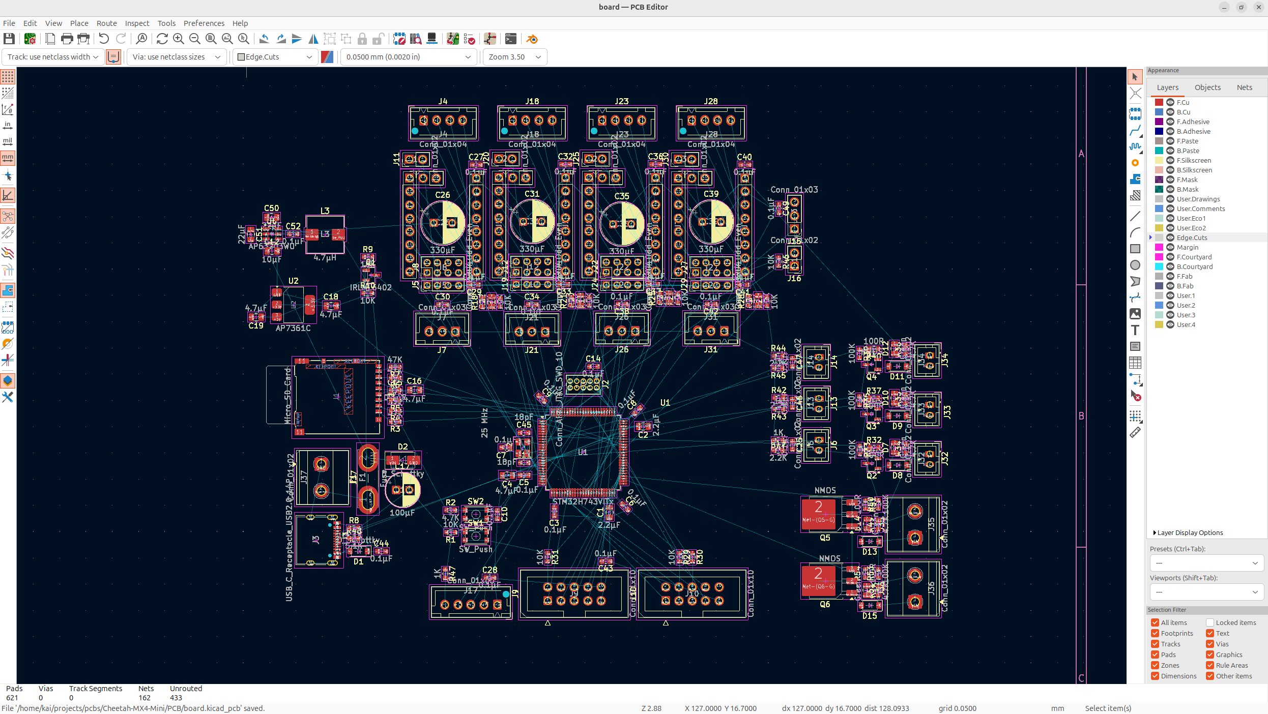
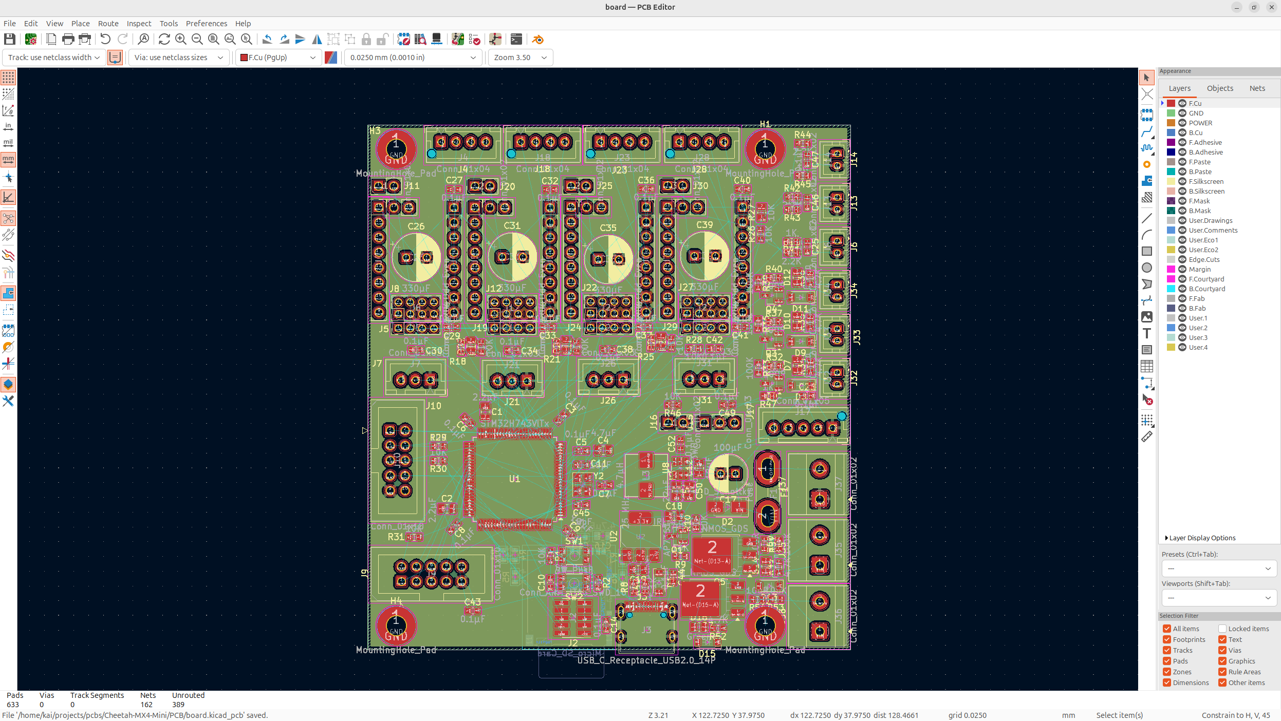
So I spent about 2 hours just fixing all the minor issues with my board and then got to the real stuff. First I distributed all the components so that similar components were by each other:
This gives me a solid idea of where everything goes, and if stuff is right or wrong. Next I worked on the MCU, now this is my first time organizing components for an MCU so I needed a lot of help from some people, but this is where I got so far:
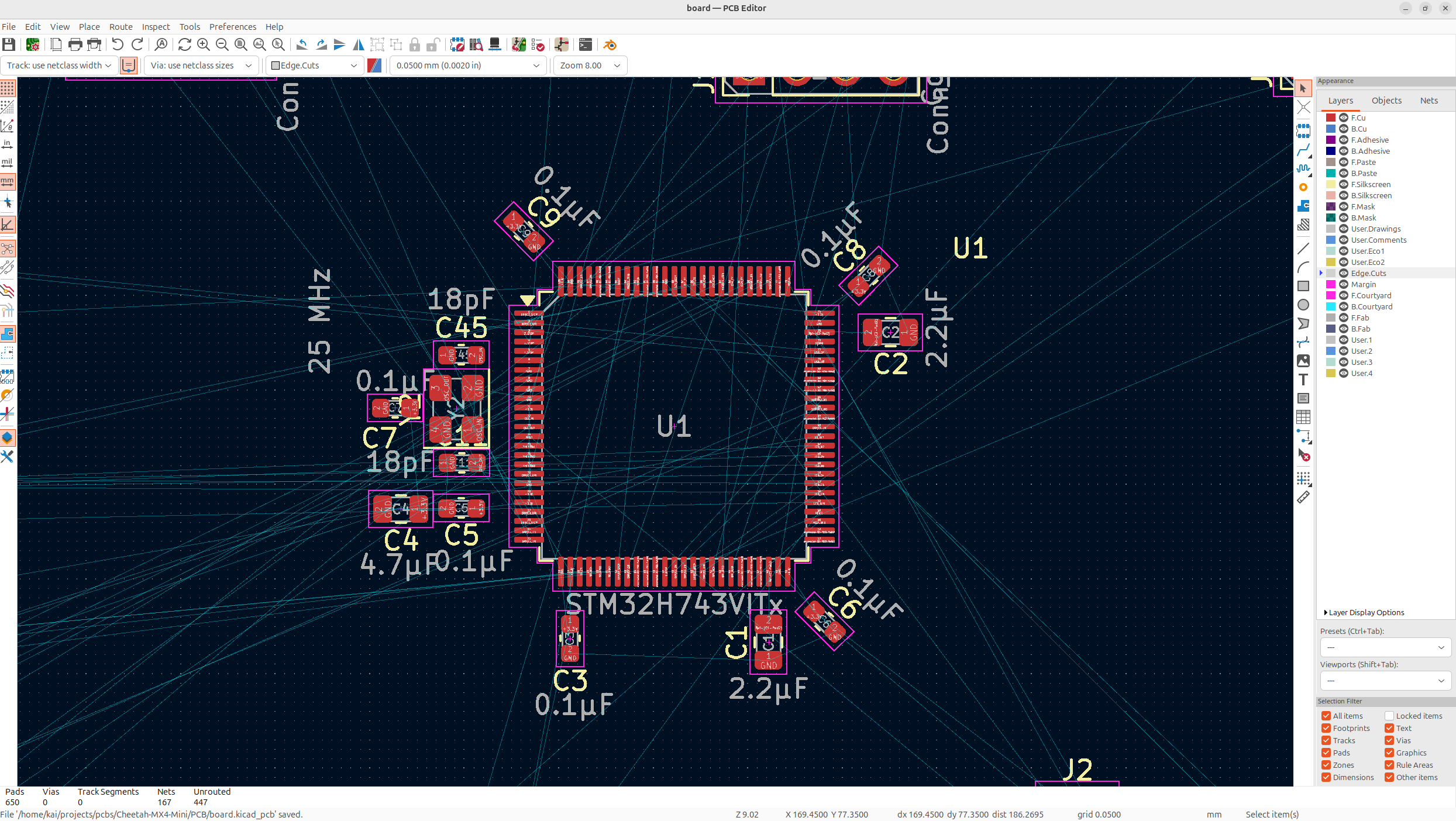
I think it's pretty good, but of course later, I'll ask for some suggestions from some people.
Anyways, after that, I aligned all the motor drivers together, took me a solid 2 hours or so to get used to layout tools, but I got it pretty nice and precise:
Now before I did more work on this, I posted this in Kicad and Reddit and got lots of good suggestions.
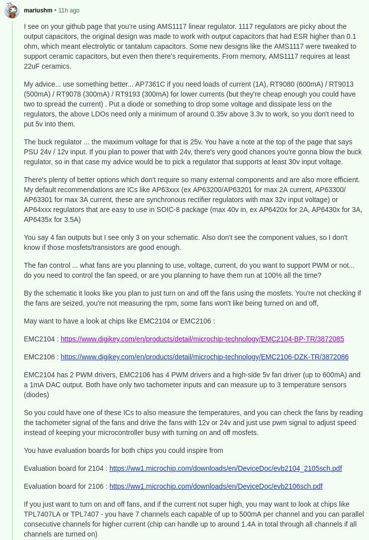
So I've switched the buck converter AND the LDO (though the LDO was a drop in replacement so I only changed the name), and I also fixed up the USB/PSU 5V switching mosfet.
It was pretty boring so I'll just show the final schematic:
I also added no-connect flags to the entire MCU, but no one really care about that
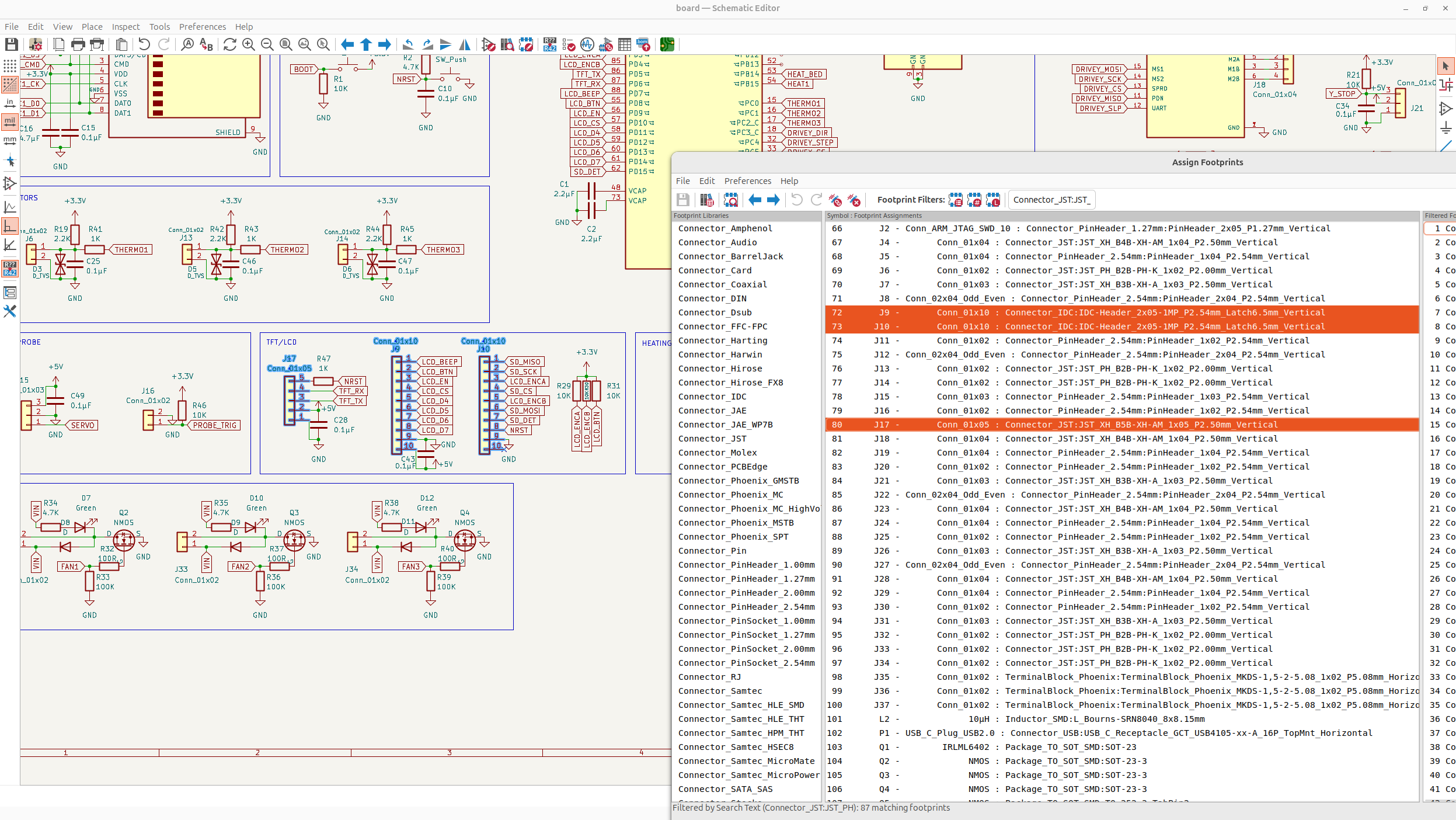
I then re-assigned all the footprints and went back to the PCB! I did a bunch of organizing components some more, I'll show that in the next day though because there will be more to show.
Day 8 - Fully Organized PCB - 10 Hours
Now while organizing my PCB, I had to switch a lot of things, notable, every single diode footprint was off and a bunch of resistor sizing's and stuff were wrong too.
It probably took me a solid 2 hours to get all the footprints straight for a second time but it turned out pretty well.
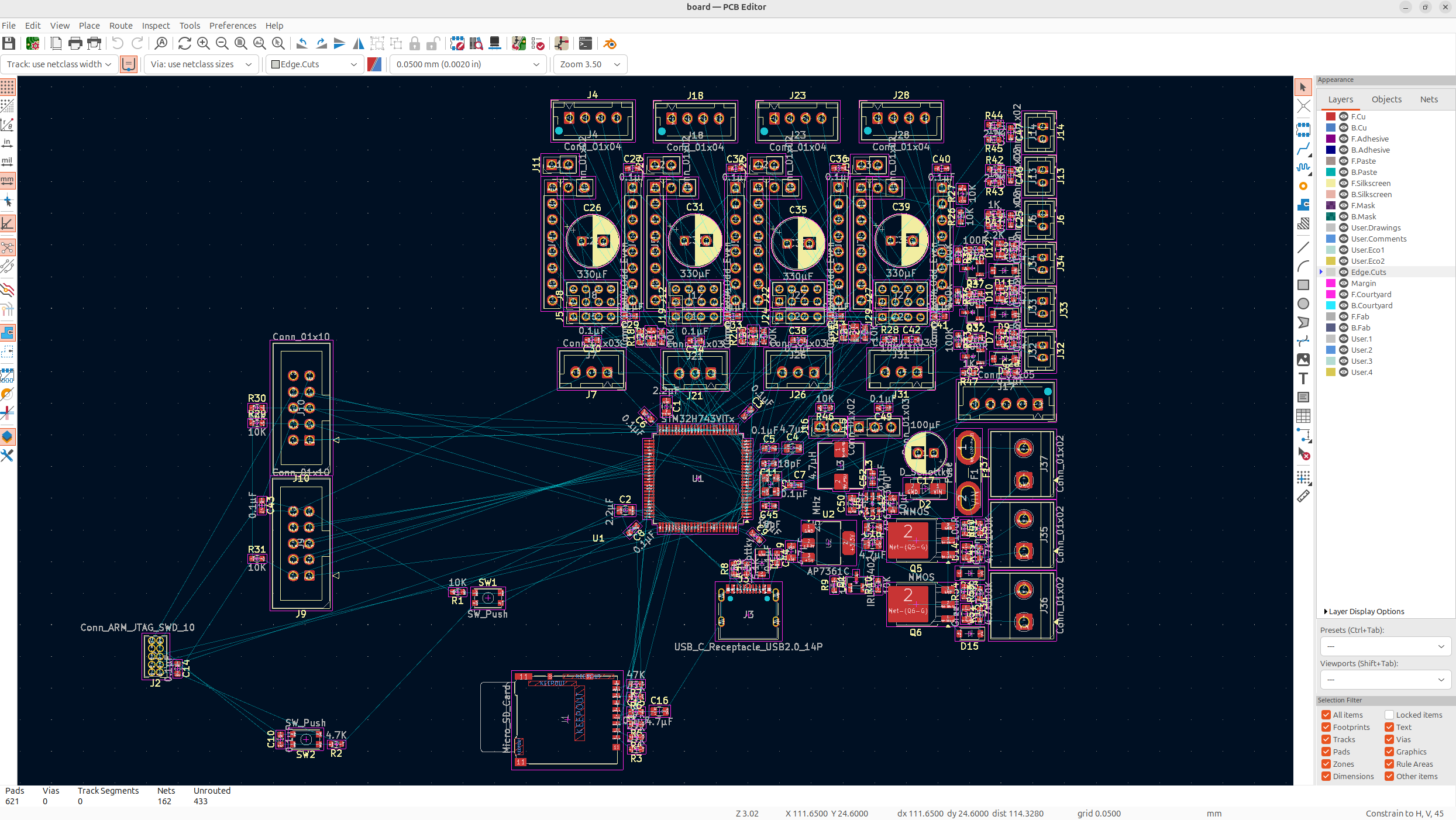
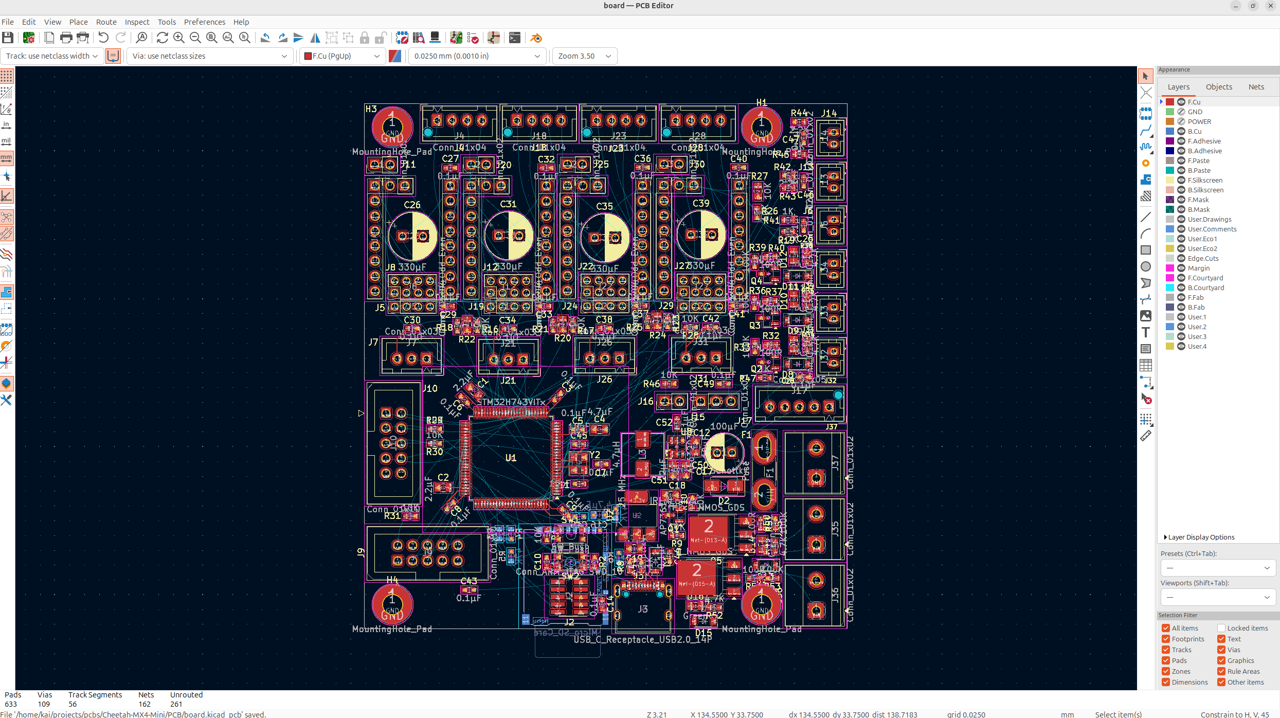
Anyways, I then proceeded to spend a couple hours laying out all the components to be perfectly organized, and I got something very nice!
Now this organization took way longer than I thought it would because LOTS of the footprints were off, and and then I had to keep on adding suggestions from people which made me change them more, like switching the buck and the LDO, and it's a never ending back and forth.
Anyways there's still some stuff like the positioning on some of the things aren't right for the diodes that I fixed so I kind of need to fix that stuff.
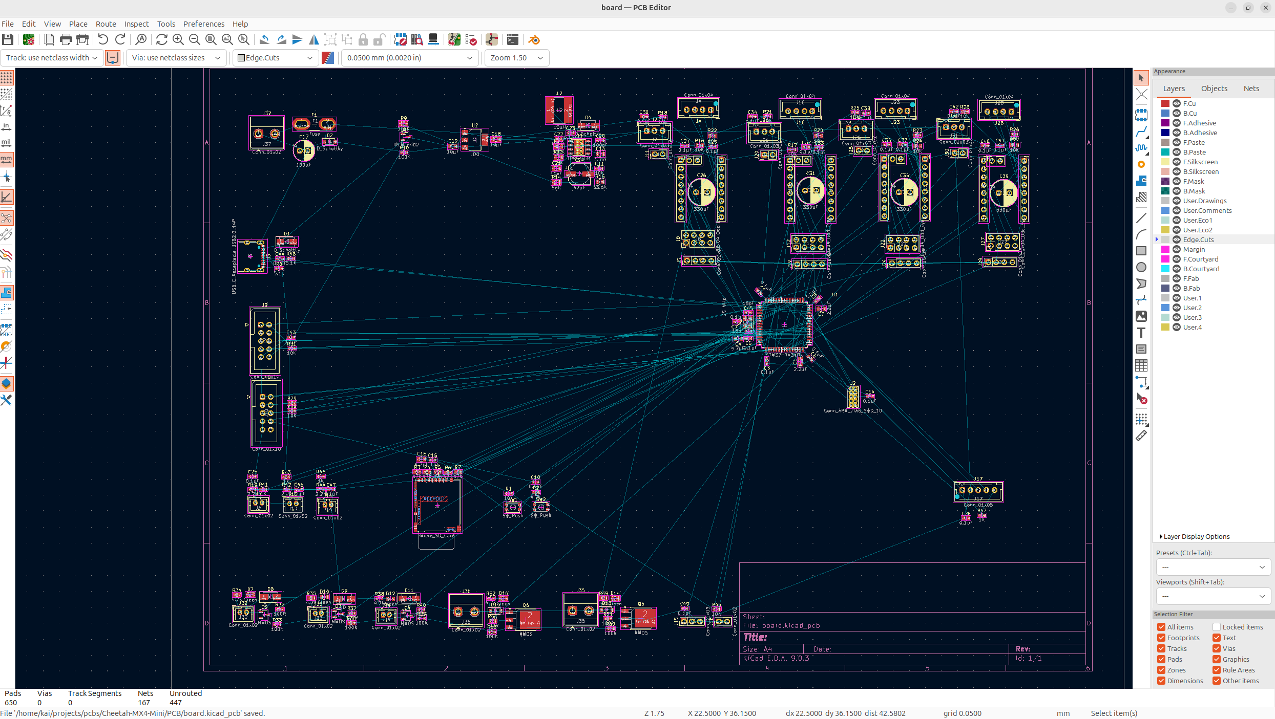
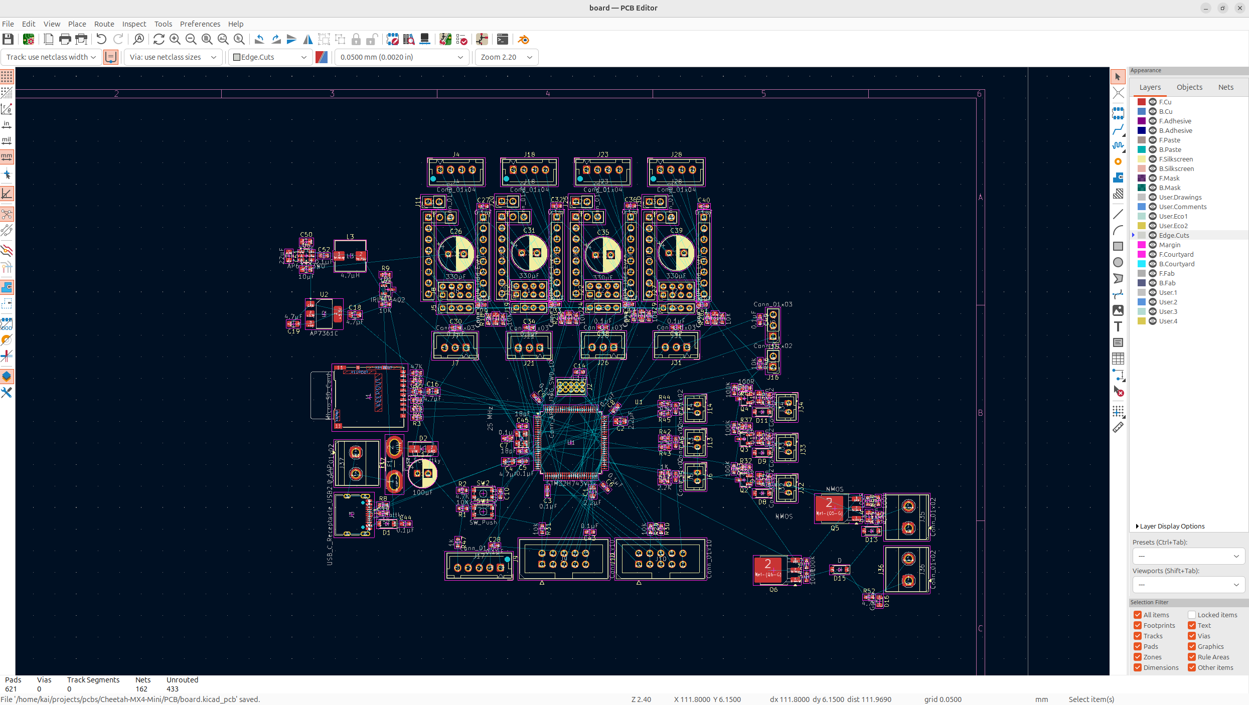
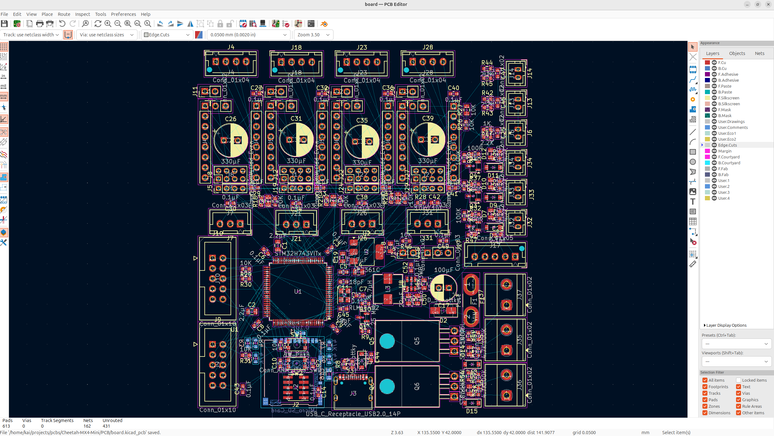
And after a bit of time and some more review from the guys on the KiCad discord server, I have a PRETTY solid organization:
I then compressed all the parts together to get this:
I make it seem easy of course, but this is after like 4 rounds of iteration so when I go to route, it's pretty clean!
I posted this on the KiCad discord server and then Salmon (my favorite KiCad elf) pointed out that the NMOS's on the heaters aren't the right footprints! So now I gotta fix those! Also thanks so much to Salmon on the KiCad discord server, probably one of the most helpful people I've met online.
And then after an insanely absurd amount of time, I've gotten to something very nice!
Now I just have to orient all the silkscreen so it's nice and organized, and then do the finishing alignments, and it'll be ready to route!
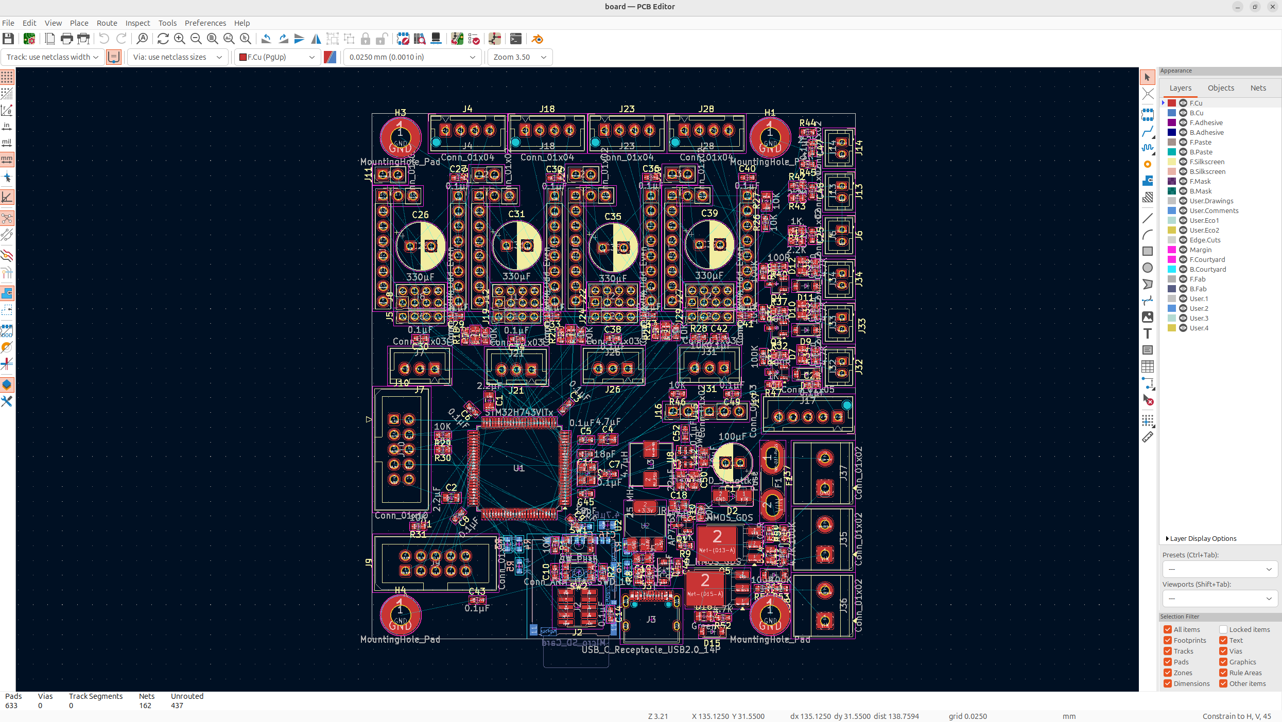
I also forgot, I still need to add some mounting holes, so after adding those, I added the edge to define the PCB, and it's pretty much ready to route!
I did a bit more messing around with the organization just to make it a bit cleaner to route, just moving parts basically so rat's are closer to each other.
Now the stackup of my board is going to be as follows: F.Cu, GND, POWER, B.Cu, so I'm going to add the 4 layers onto the board, and then do a power/GND fill:
Anyways I'll save the rest of the routing for tomorrow!
Day 9 - Routing the PCB - 12 Hours
Now I got a lot of stuff to do, I gotta route this entire PCB and I don't have much time left to submit!
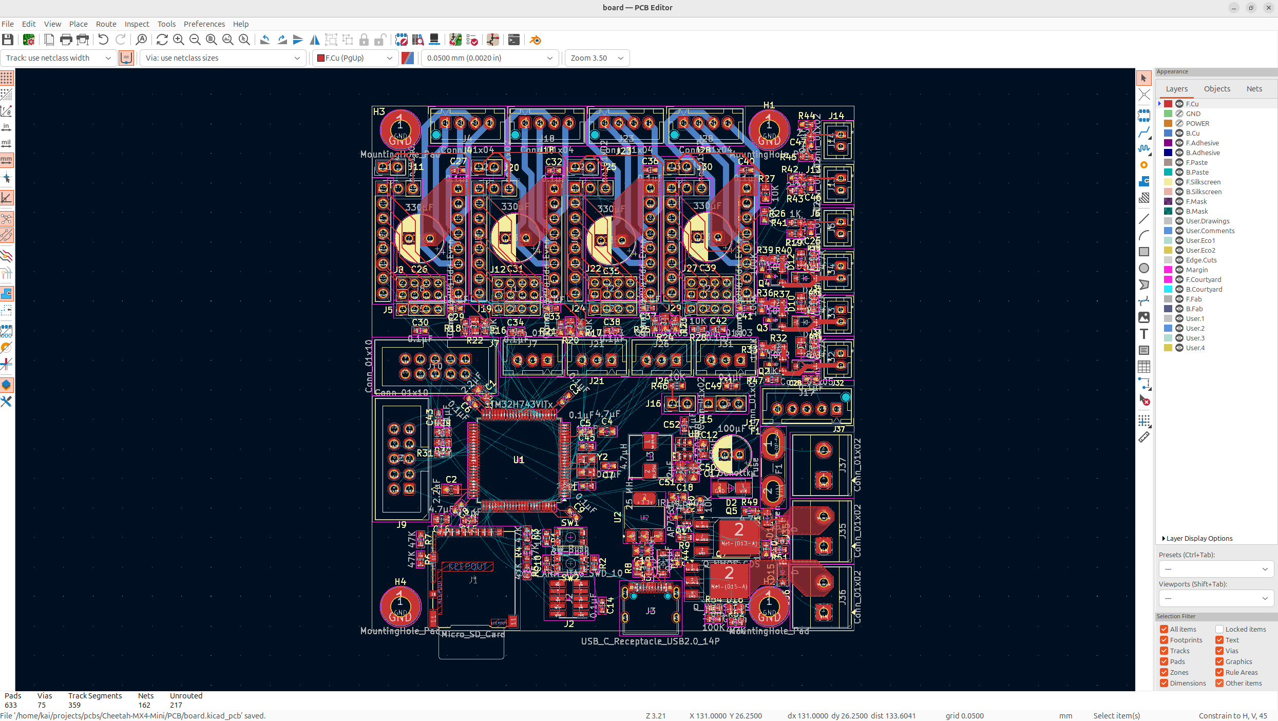
First I added all the via's to the ground and power planes to connect the ratlines. I also fixed some intersecting parts which wouldn't work! Way less ratlines now!
And then I usually start with the chonky things that take lots of current or voltage, you kind of just want to route these based off current size, voltage and noise levels, and also what's close:
Signal pins are small, high current is large, high voltage depends.
And then I improved the power a bit more, and I wired some of the smaller stuff on the board!
Mind you, these screenshots are nearly 3 hours apart, this is NOT a short process. I'm also still a beginner, so I need a lot of help from others when designing this, so I'm constantly iterating on it!
And then I got a really good suggestion to move the enstop connectors so that I could fit the SD Card on, so I deleted like half my traces and put it on!
Looks WAY better! This is absolutely sick!
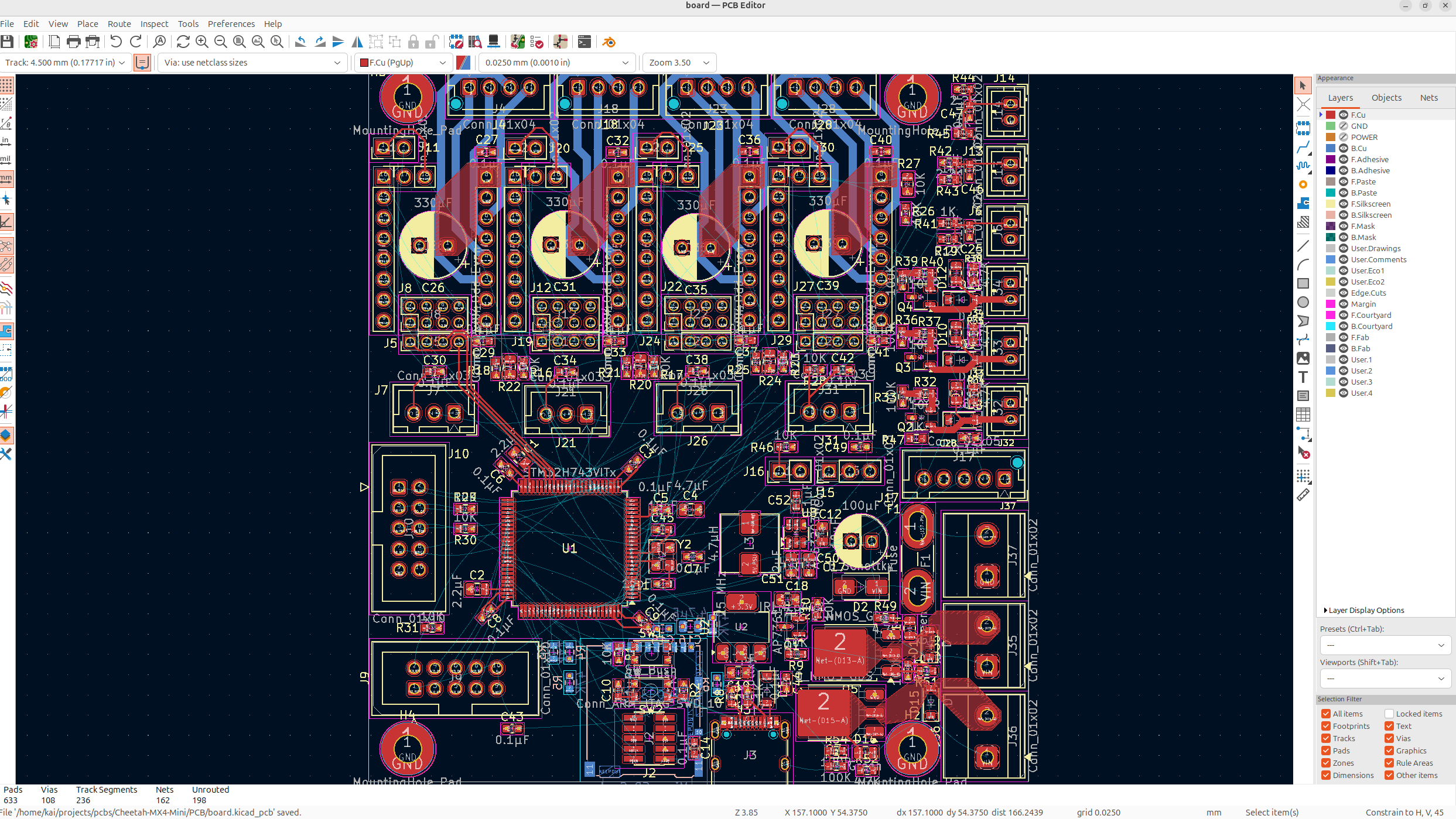
After all this, I did all the signal pins from the MCU pretty much, I try to stick to one color going one way, the other color going the other way, and planning the routes out in your head beforehand helps alot!
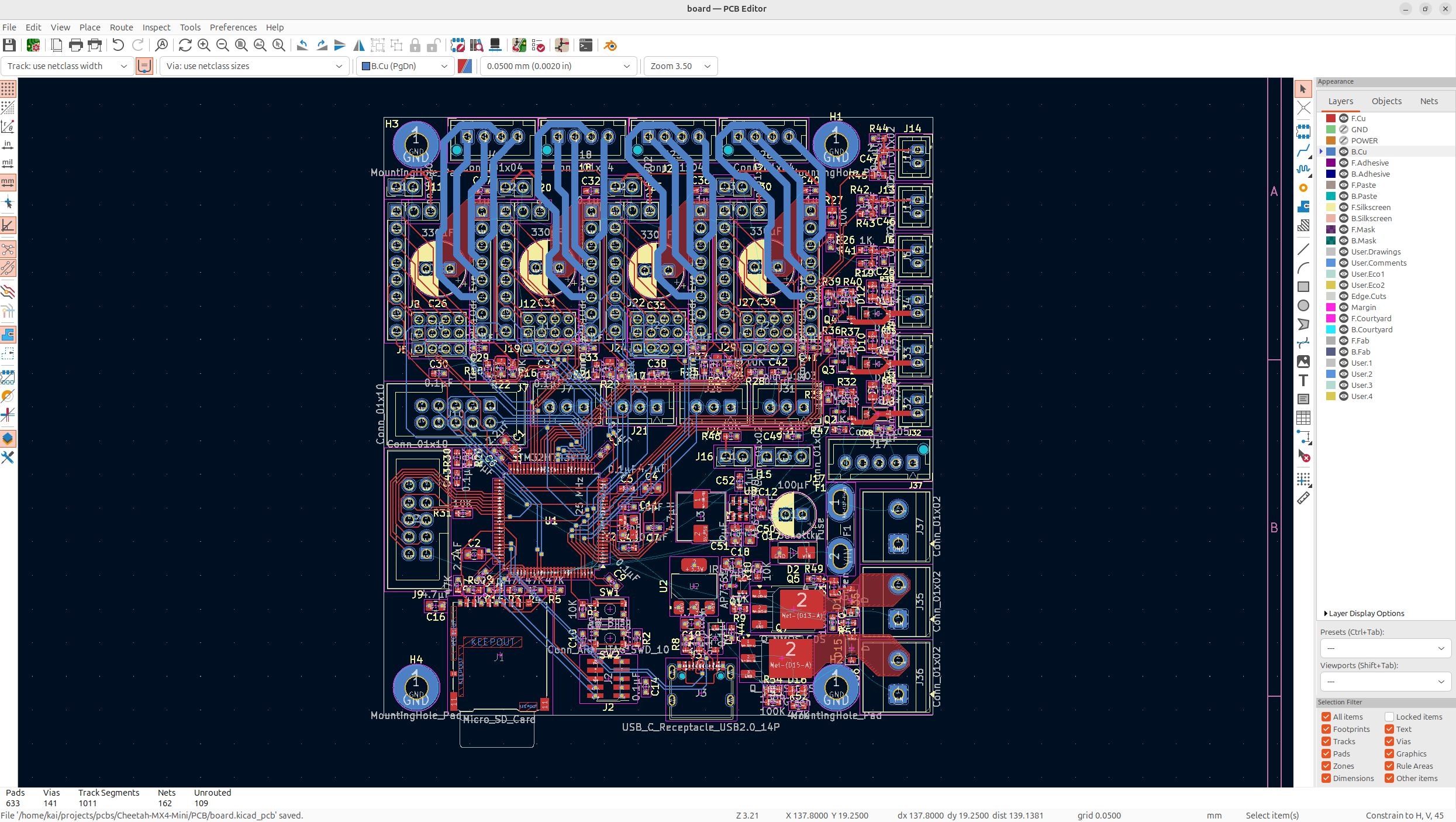
Anyways I finished up all the signal routes, and it looks beautiful! There's not much to say about it, except for it took a LONG time.
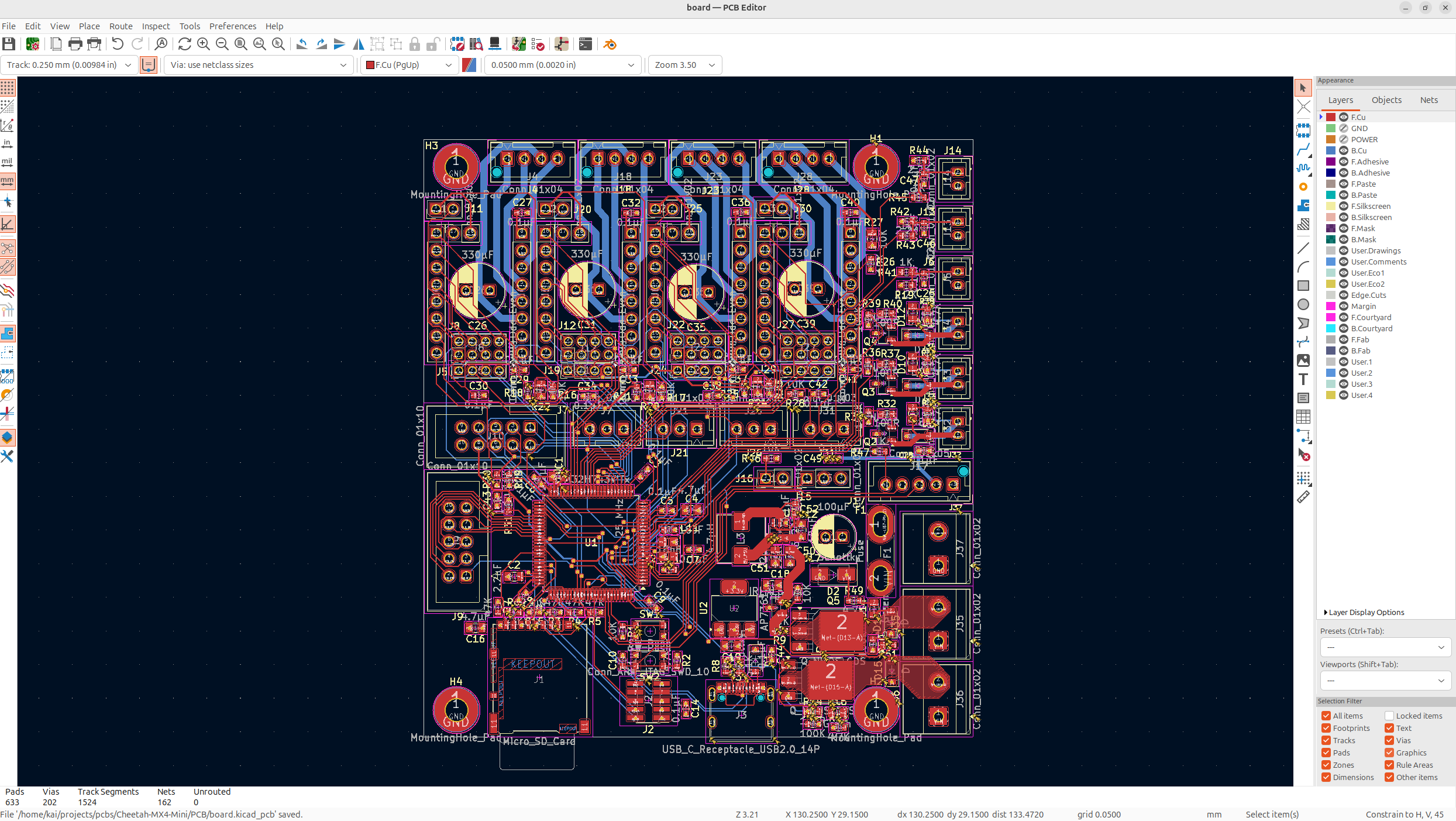
And now I just have to add the power plane. The VIN power rail will be the largest, followed by the 5V rail which is a bit smaller, and then I can just attach the stuff that kind of needs more and less current like so:
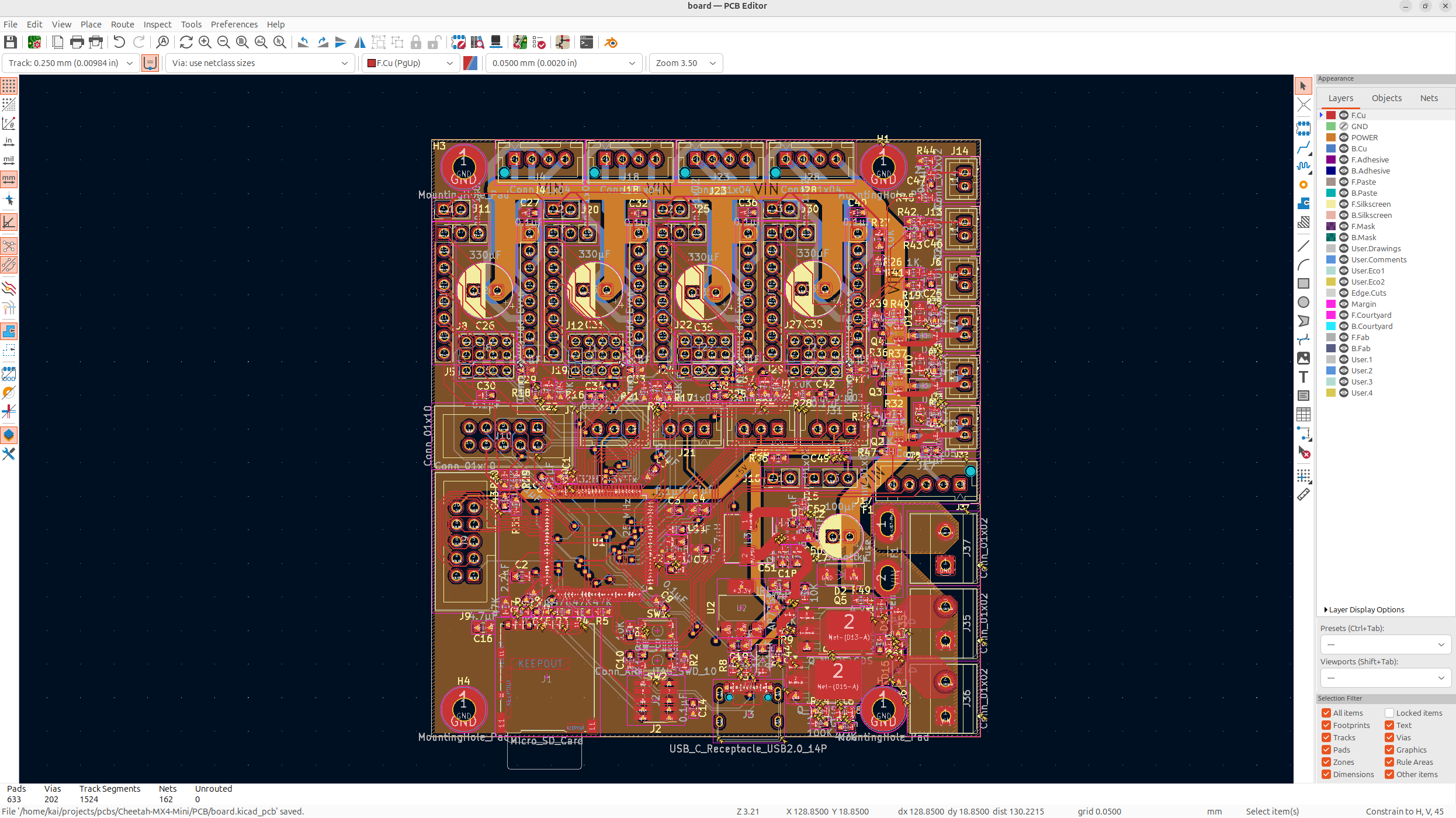
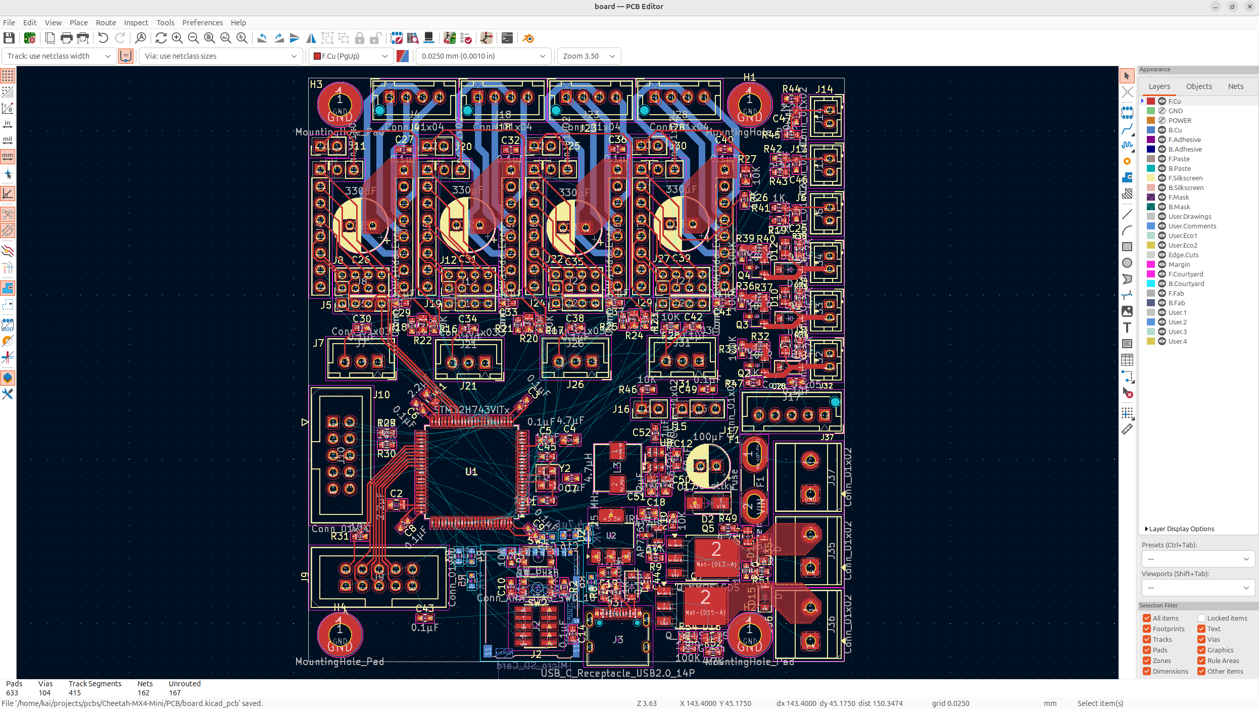
The important thing I had to keep in mind during this was the large current of the heater's, and that's one of the reasons I put the VIN so close to them, because they need high current, so I can just do a ground fill there.
Anyways, now I just have to fix all the DRC errors and we'll be good! There were about 30 errors, I fixed all of them up, nothing too crazy, mostly just unconnected things, and this board is BEAUTIFUL.
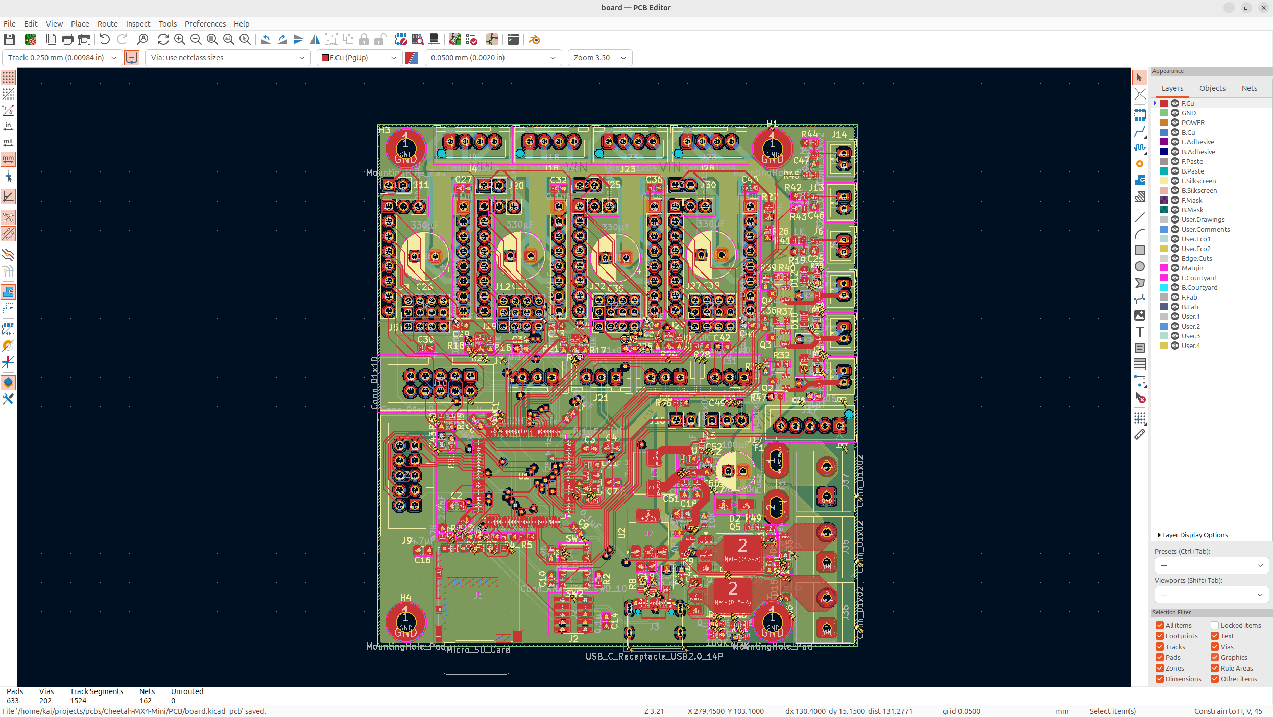
At just 80x90mm this is a powerful, yet small and affordable board, it's beautiful!
Now I'm pretty dead inside and exhausted from making this board, this was shear insanity, but it turned out absolutely amazing!
To anyone reading this, thanks so much to @Fisheiyy on GH for all of his help and the people on reddit for helping me too!