
Pr1sm
Total Time Spent: 23 Hours
Day 1 - PCB Schematic - 3 Hours - July 7th
The PR1SM keyboard is going to be a simple, stacked acrylic keyboard that will have some back-lighting. I want a blend of functionality and aesthetic so I'm going with a more simple design that's still decently complex.
I'm going to take inspiration from the MX Mechanical keyboard for the layout and just remove the numpad, because let's be honest, no one uses that.
So let's get started with a simple layout. I'm just going to be using a Pi Pico or maybe an Orpheus Pico, but they have the same footprint so I'll just stick with a Pi Pico for now.
I did the math for the keys and there's 89 in total, so let's add all of those on.
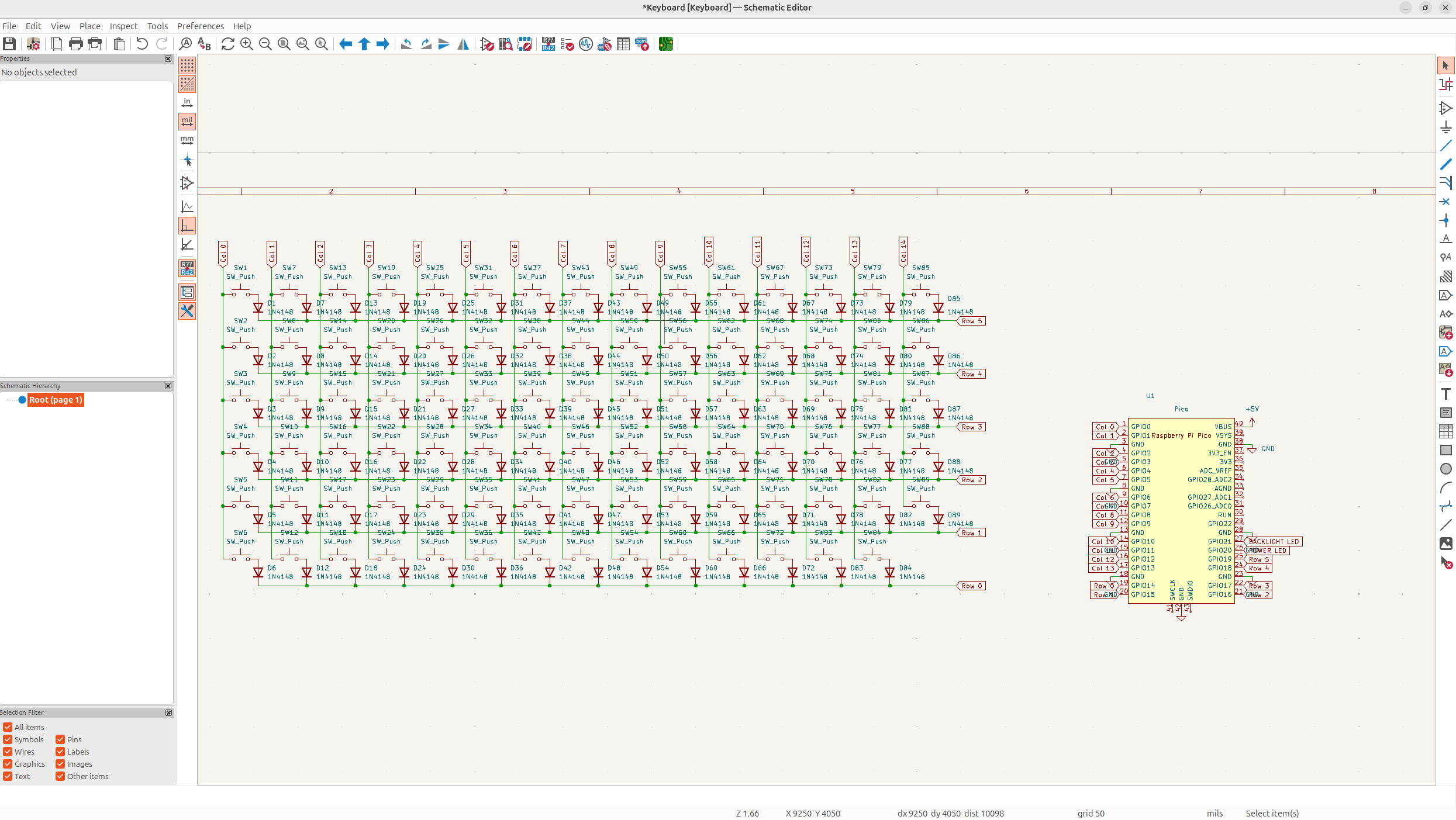
Next I want to have a small power LED, I'm just going to make this separate so I don't need to do some annoying programming, and also because it's got a different footprint so it makes a bit more sense.
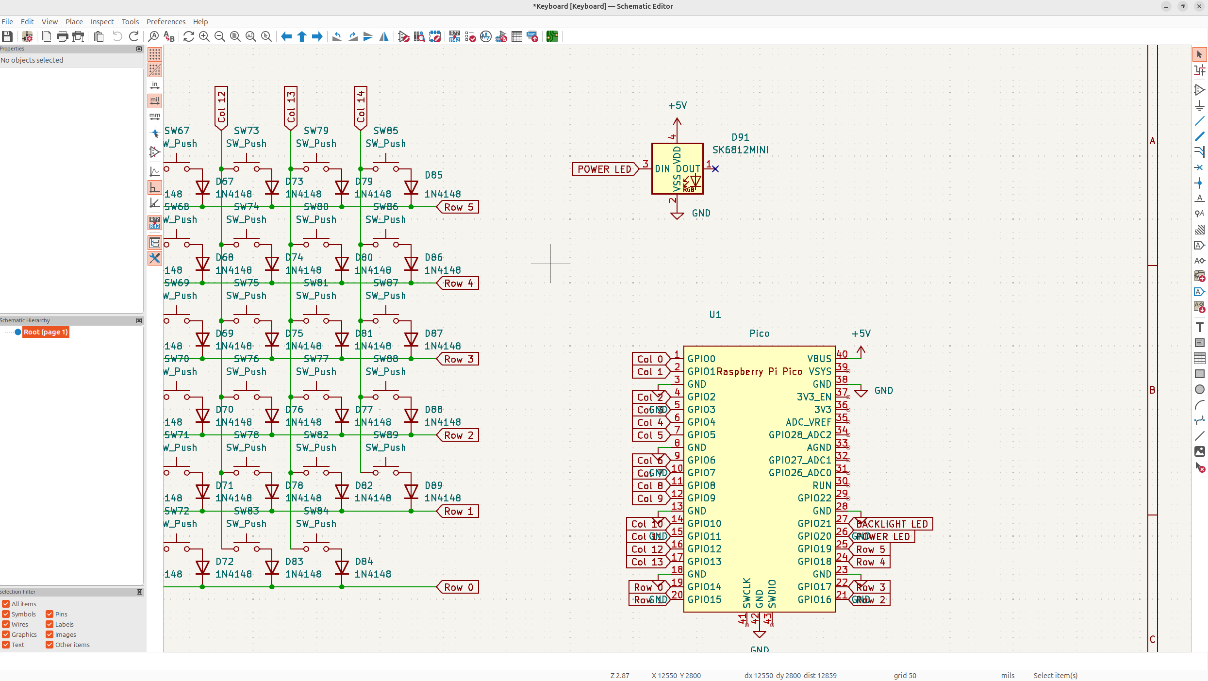
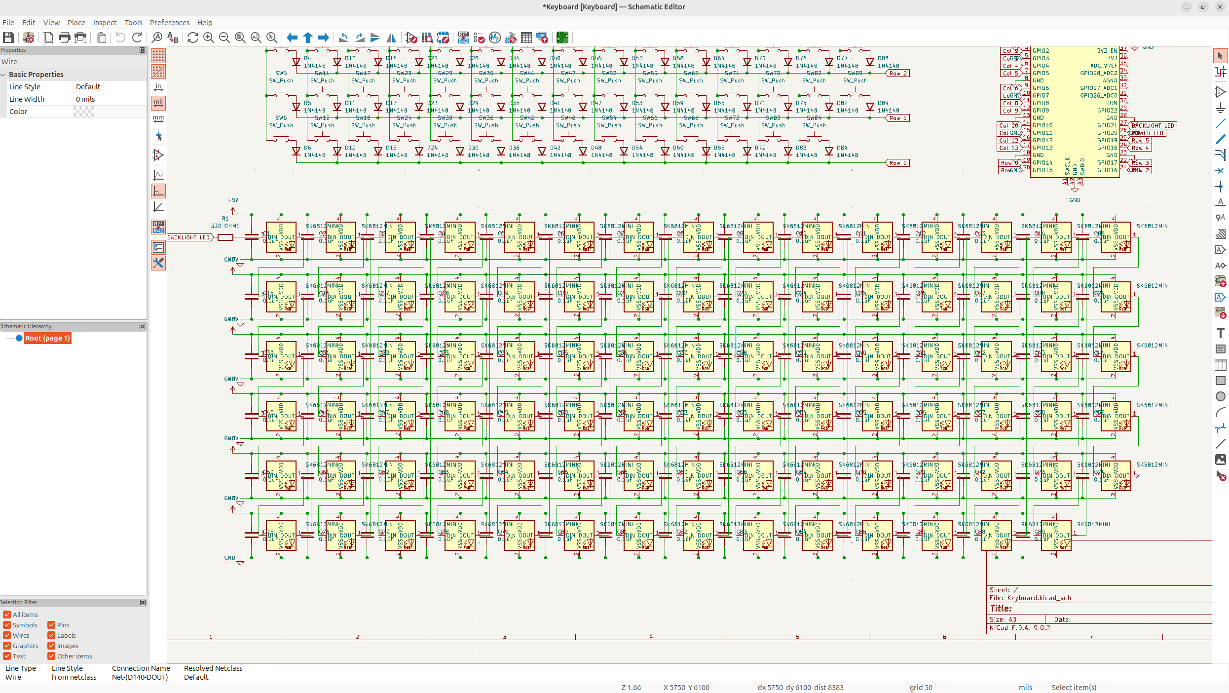
Next I need to add all the neopixels. I need one for every single key, and I'm going to put a 330 Ω resistor on the data line to smooth the connection out, and then I'm also going to use decoupling capacitors to stabilize the power a bit. The caps are just going to be 0.1uF ceramic caps.
Now that's the entire schematic done. I wanted to stick to best practices, and I personally think it's pretty clean, but I went through quite a bit of variations just to make sure I had the right amount of neopixels and keys so it took quite a long time.
Day 2 - PCB Wiring - 8 Hours
Next I needed to wire the PCB, now I'm just going to describe the process of wiring the final one, but I will say, I re-wired the entire thing over 4 times because I wanted it to be pretty clean and stick to good practices.
Now this PCB still isn't perfect, it actually has a lot of flaws, but I think it's a pretty good way of doing it for a 2 layer board.
So what I've decided to do for this board, is have a ground fill on the bottom, and then put via's on all the neopixels power, and do a power fill on top. This will give good voltage to the neopixels, while being pretty clean, and the ground will reduce the noise, which I believe will lead to a pretty nice board.
But anyways, first I had to do the layout. I just set a 2.38125mm grid and then halved that for smaller parts.
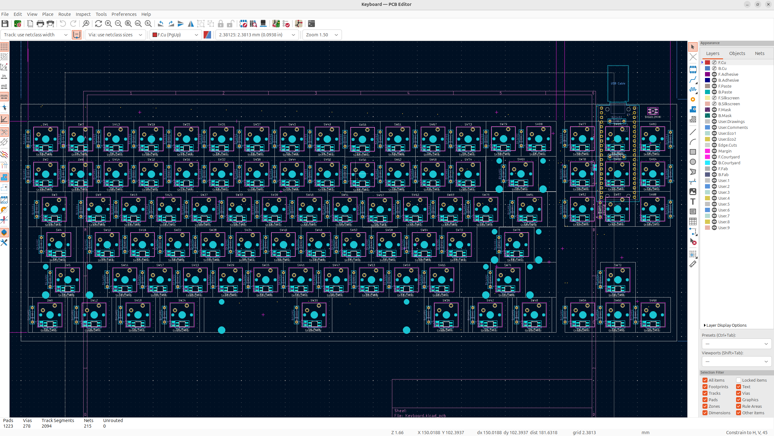
You can see it's a pretty clean PCB, I used reverse mount footprints for the neopixels and then I put the Pico on the back under the keys to maximize space, and I know it'll look really good the actual PCB. Though the PCB will probably bring up some issues because some of the resistors are there, so I need to solder it with enough of a gap for the resistors.
I also need to leave some space underneath the case for the Pi Pico to sit, so it might be a bit annoying, but I kind of like how this will make the actual keyboard look good.
The neopixel footprint was taking from ebastler's repository and they're just mounted underneath cherry mx keys which will specifically have holes for the neopixels.
Anyways now that everything was placed, I need to wire everything. I kept with doing back lines going horizontal and then red lines going vertical, which is a really nice way of wiring stuff.
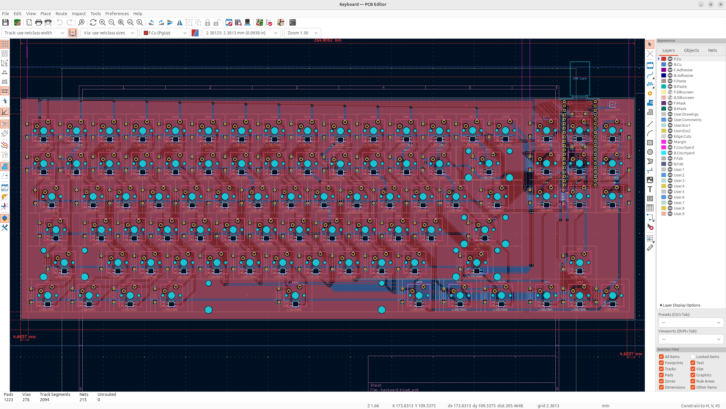
Then after that, I added via's to all the neopixel power lines, and did the ground fill on the bottom and the power fill on the top layer. Now I've used around 300 via's and 2100 line segments... but it'll be fine hopefully.
It's quite a complicated to wire board for just 2 layers, but it should be okay, and will hopefully look good.
You can also see, I wired the resistor as close to the start of the data line as possible, which is crucial.
Then I put the decoupling capacitors right next to the power lines of the neopixels along the power fill.
I had a lot of thermal relief errors when doing this, but to fix them, I just adjusted the lines so the fill could pass through. I might've had less of these if I switched which side was ground, and which side was power.
Anyways, next I had to add silkscreen and colors. I opted to go for a white board, with black silkscreen because I feel like a stacked acrylic keyboard is pretty clean, so it'll look sick.
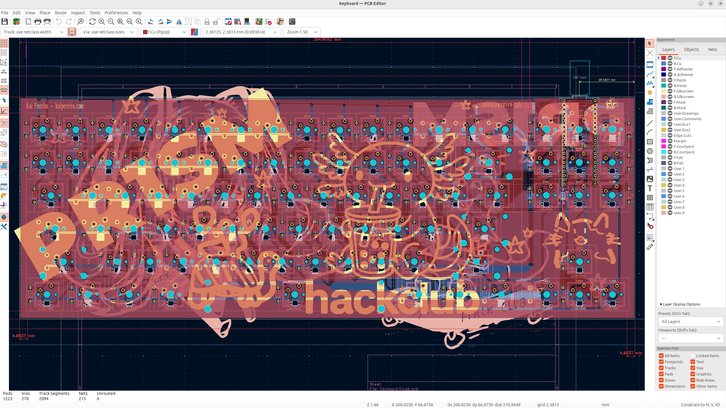
I drew/made half of these, and then AI generated/found the rest of the designs for the silkscreen. And I think the board turned out really well!
But before I took the 3D model of the keyboard, I needed to add 3D models to all of the footprints which took quite a long time, but it wasn't too bad.
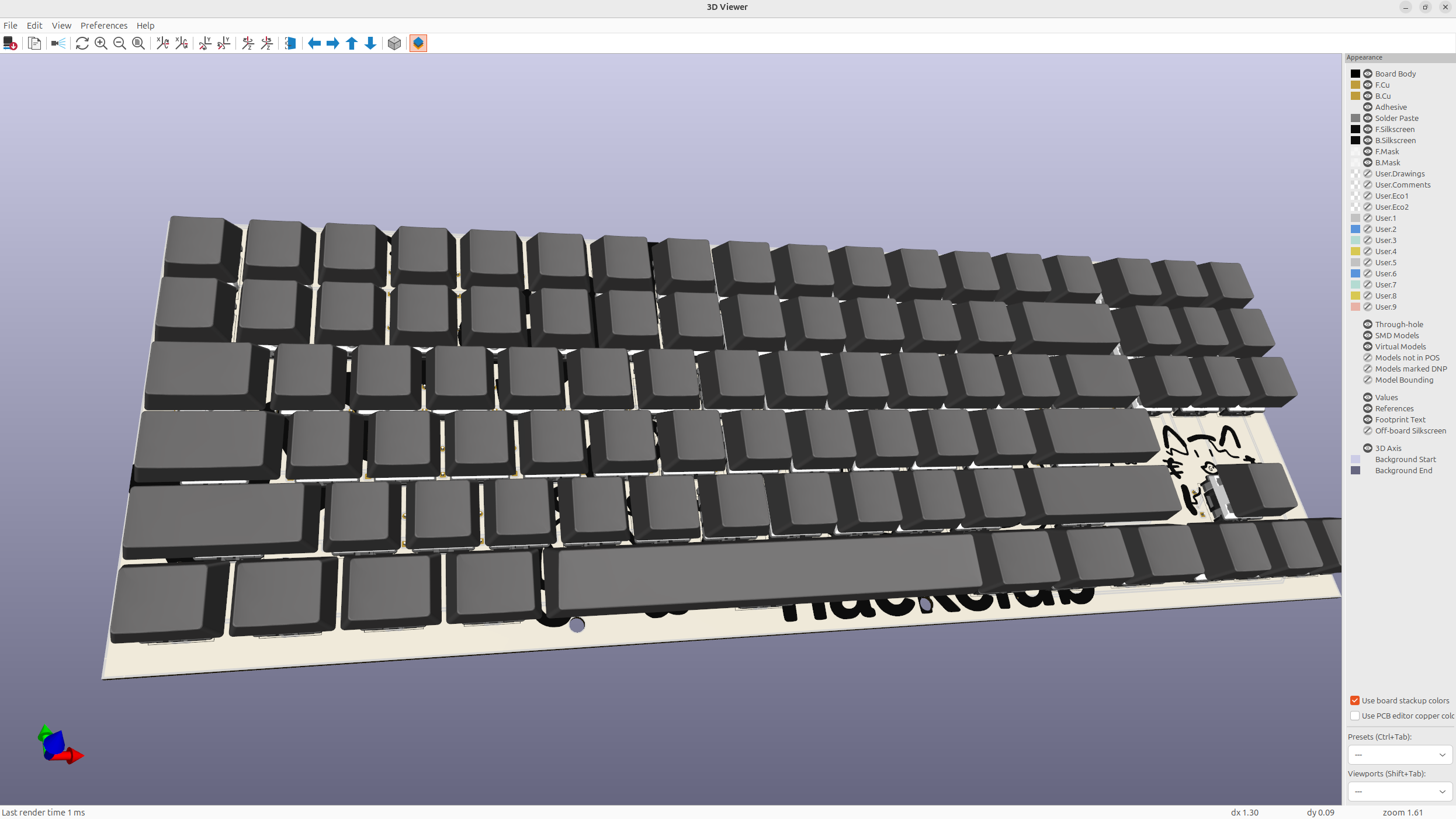
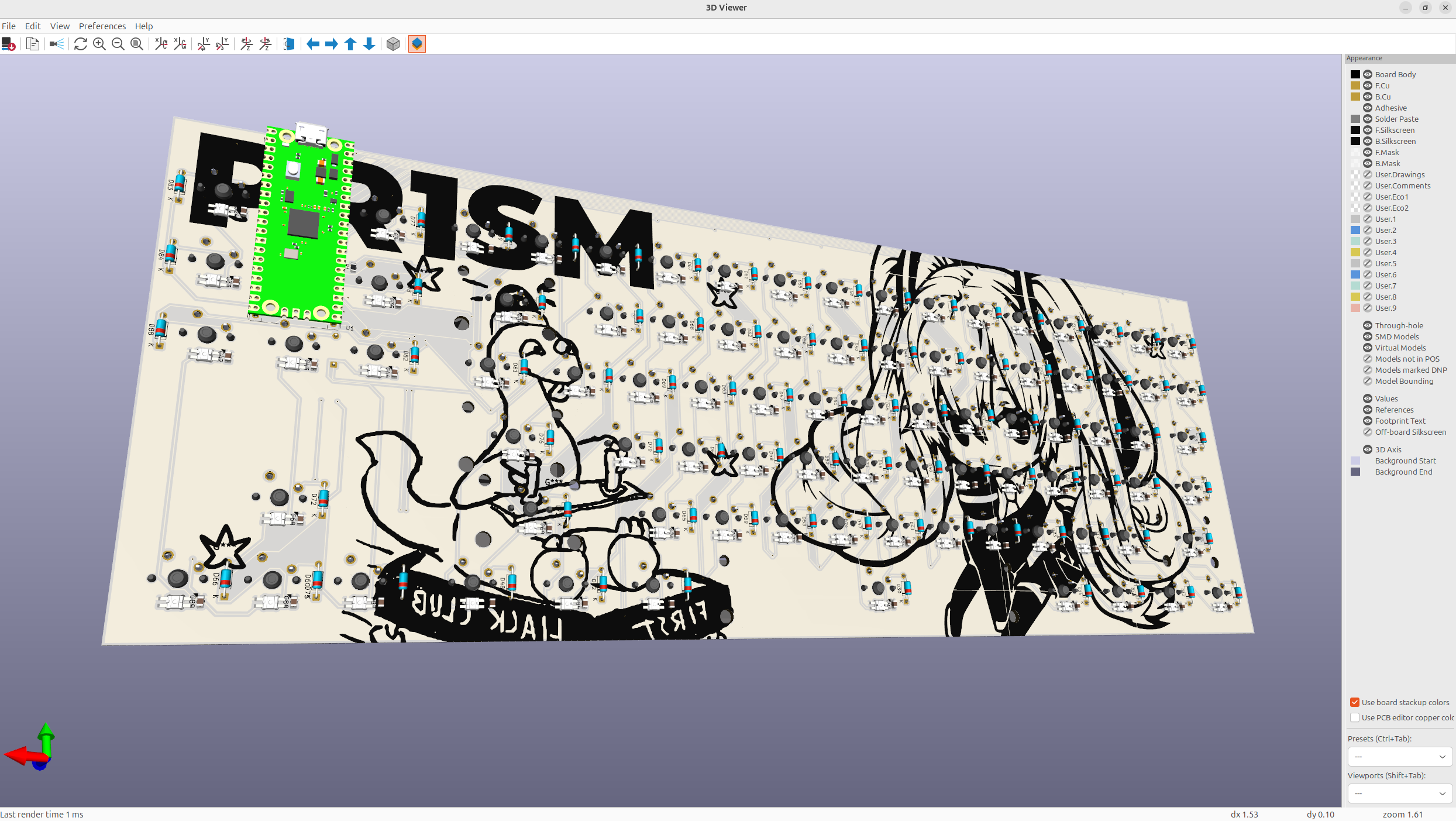
And personally, I think this board looks absolutely sick, the branding text on the board, really makes it beautiful!
Anyways, this took me 4 times to wire because of small mistakes, so always plan out your wiring a bit more beforehand guys!
Day 3 - CAD Design - 6 Hours
Now I wanted to go with a stacked acrylic case which was actually more annoying to make than I thought it would be. But anyways, I sketched out the entire keyboard because I knew that I could make the entire case in one sketch conveniently.
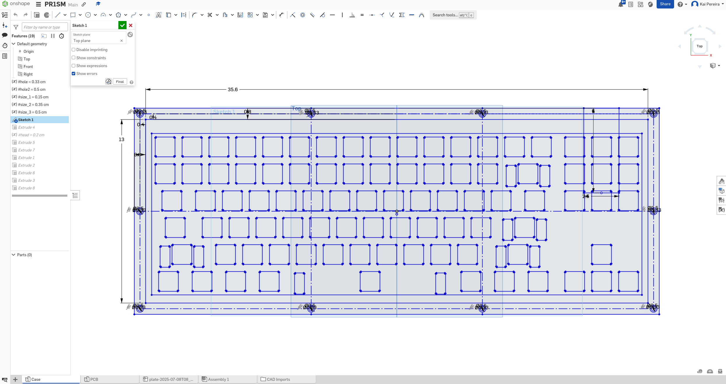
Now this sketch took me quite a few iterations, but I got the clearance on point and it looks pretty good. The main problem I was having was aligning the plate with the PCB, and for some reason, that took me a decent amount of time.
Now I needed to actually make the case, the thing about making a stacked acrylic case, is it needs to be decently thin, but also still have all the necessary layers. I also needed to design it, so it's easy to lasercut, and so everything fit pretty tightly. And after a bit of iteration, I got this beautiful board.
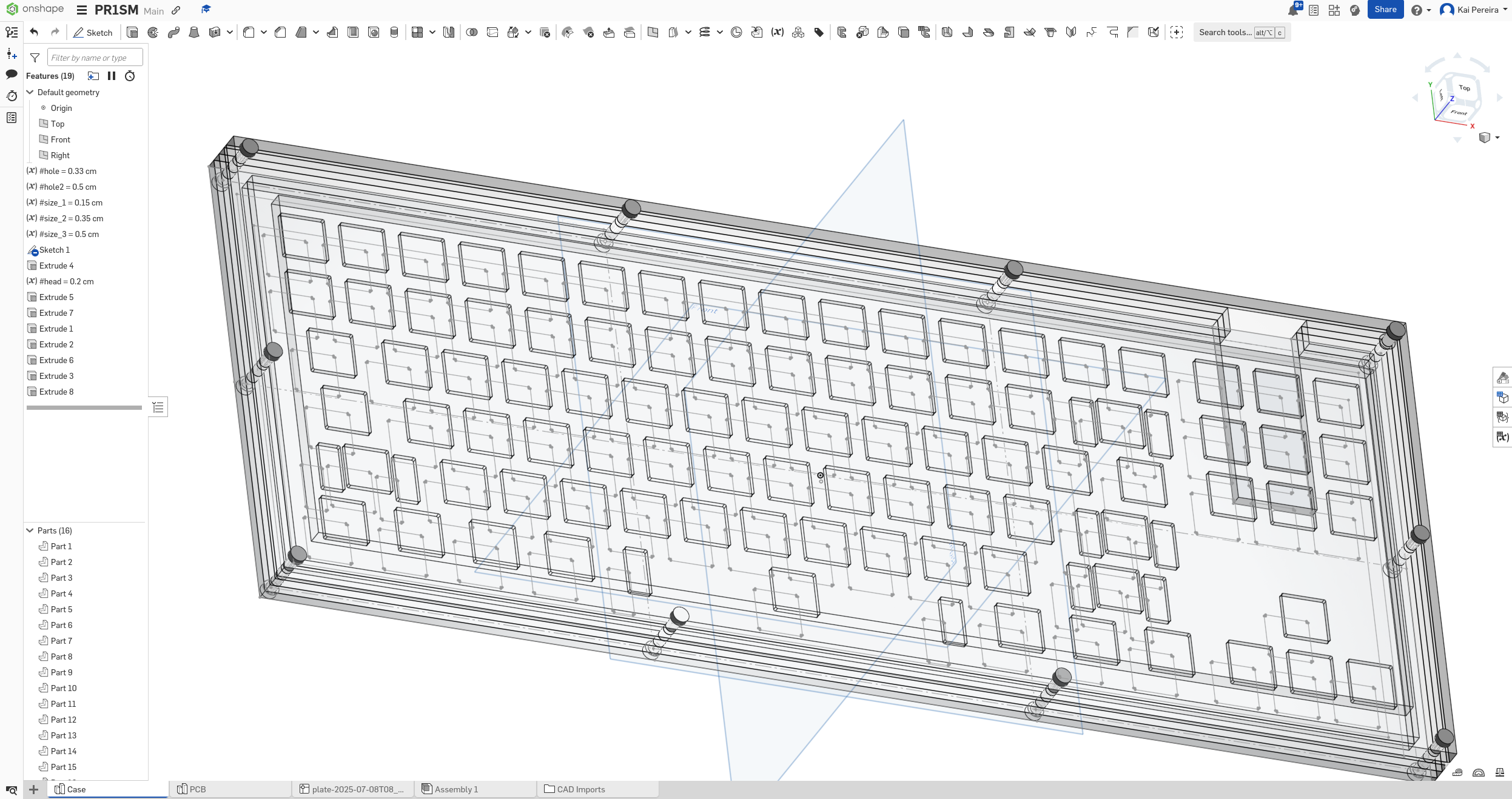
It uses stock 5mm, 3.5mm and 1.5mm thick acrylic and then classic M3 screws to hold the entire thing together. Now I didn't want it to flex too much so I added quite a few screws. I also added a cutout so that the PCB could go through the case nicely and still be able to plug in and such easily.
Now the PCB was extremely laggy because it had lots of models on it, so it took a long time to fasten each time I iterated, but here's how it looks inside of the plate
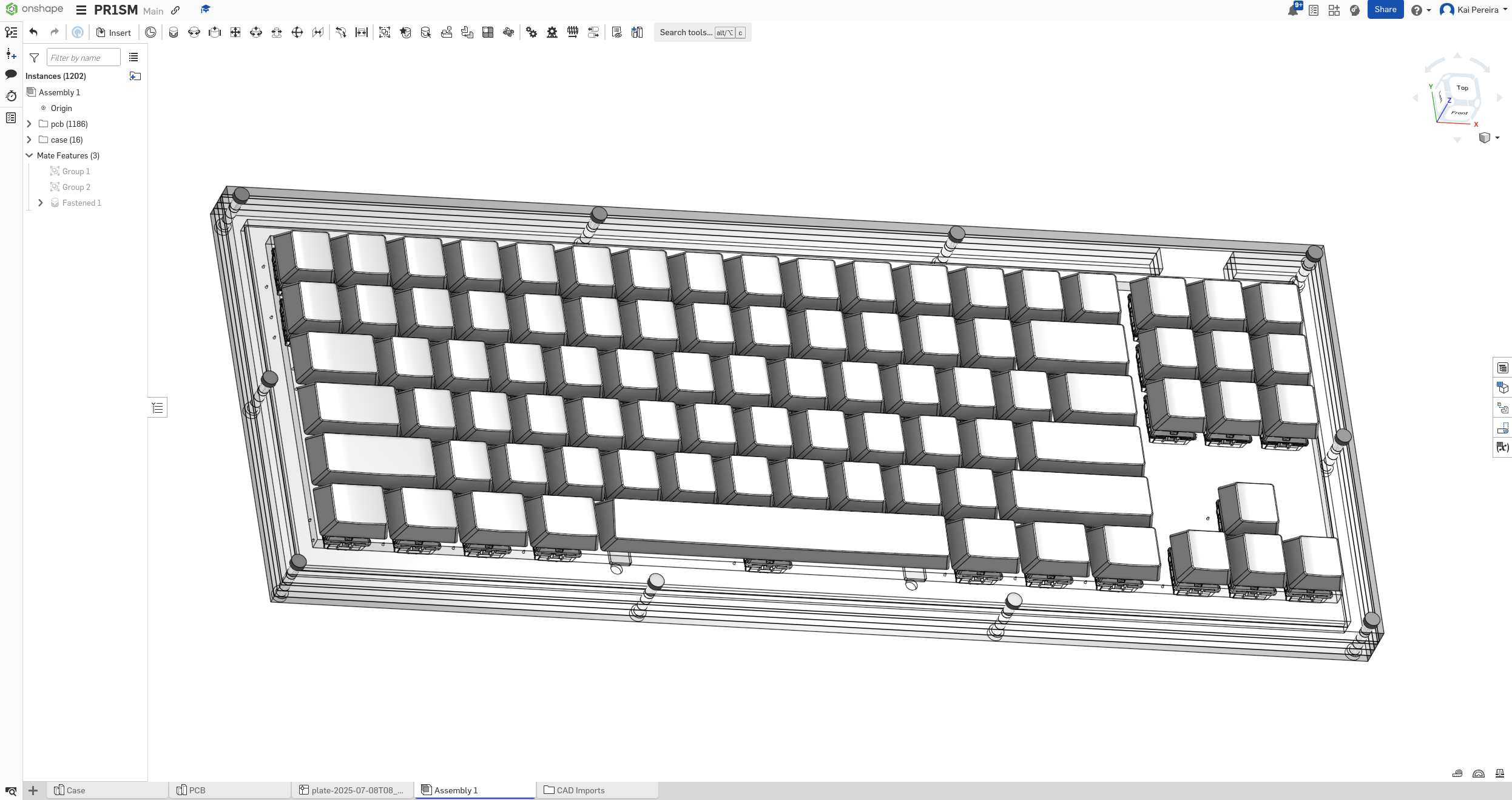
I personally think this is pretty clean, and I've taken a look at each section, and everything fits nicely together. And the MCU fits in pretty nicely, now I'm not too sure if it'll actually need this whole, but I'll put it in there for V1 just to be safe.
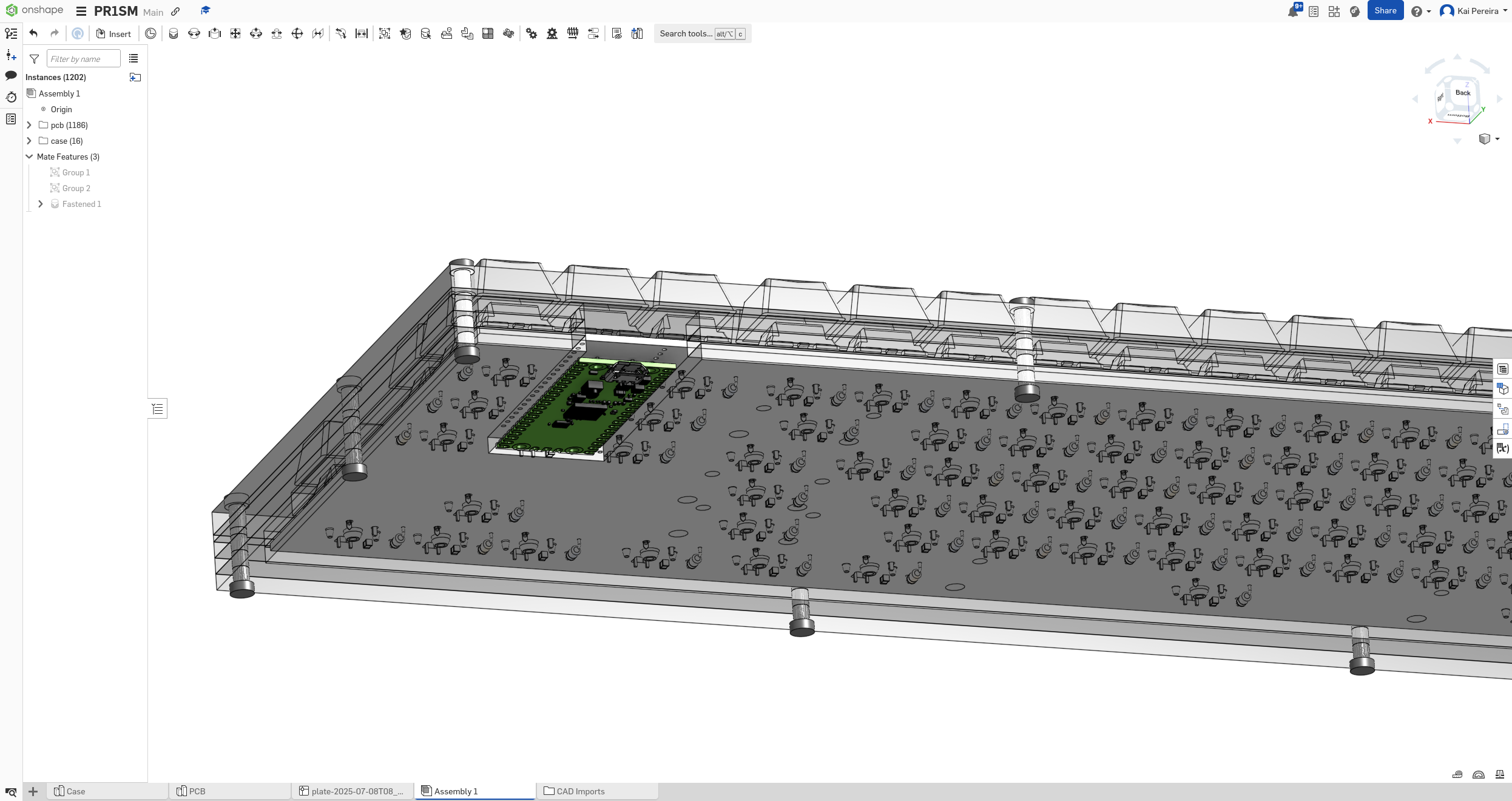
It'll be soldered a bit away from the resistors so it has some clearance space.
Now I know that it probably doesn't seem like I spent too long on this case because it's so simple, but I kept on messing up the tolerances, and also I'm not used to making something that fits in so cleanly like this. And it's laser cut, bolted in so a couple more things to take into account instead of just 3D printing it.
Day 4 - Refining and Rendering - 6 Hours
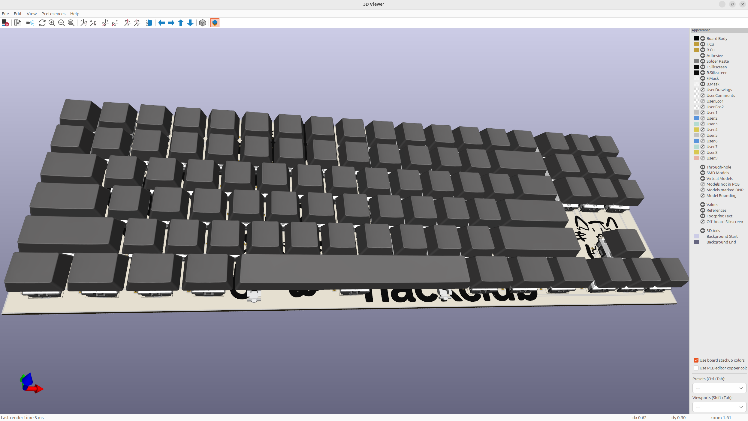
Anyways before I rendered my project, I needed to add a couple more models to the PCB so that it would look very accurate in the render. So I just added the neopixels and the stabilizers to the PCB model and re-downloaded it. I usually download the PCB as a GLB for blender because it's pretty fast and keeps most of it's details!
So next I started up a new blender project, and I also added all the blender files to LFS so I didn't have issues with large files. You need to remember to add both the .blender
and the .blender1
files to LFS.
Then I just added the keyboard model from KiCad as a GLB and we now have the base for our PCB in Blender.
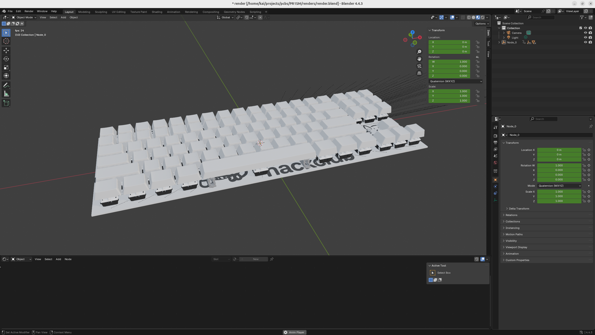
After that, I applied a slightly bumpy material to the keycaps and added in the case. The case is just going to be some transparent acrylic, and then I'm just going to make the screws ultra-metallic because I kind of like that style.
After that I added a camera angle, I figured out you could do View -> Align View -> Align active camera to active view, and you could just set the camera to whatever you were currently looking at which looks really good.
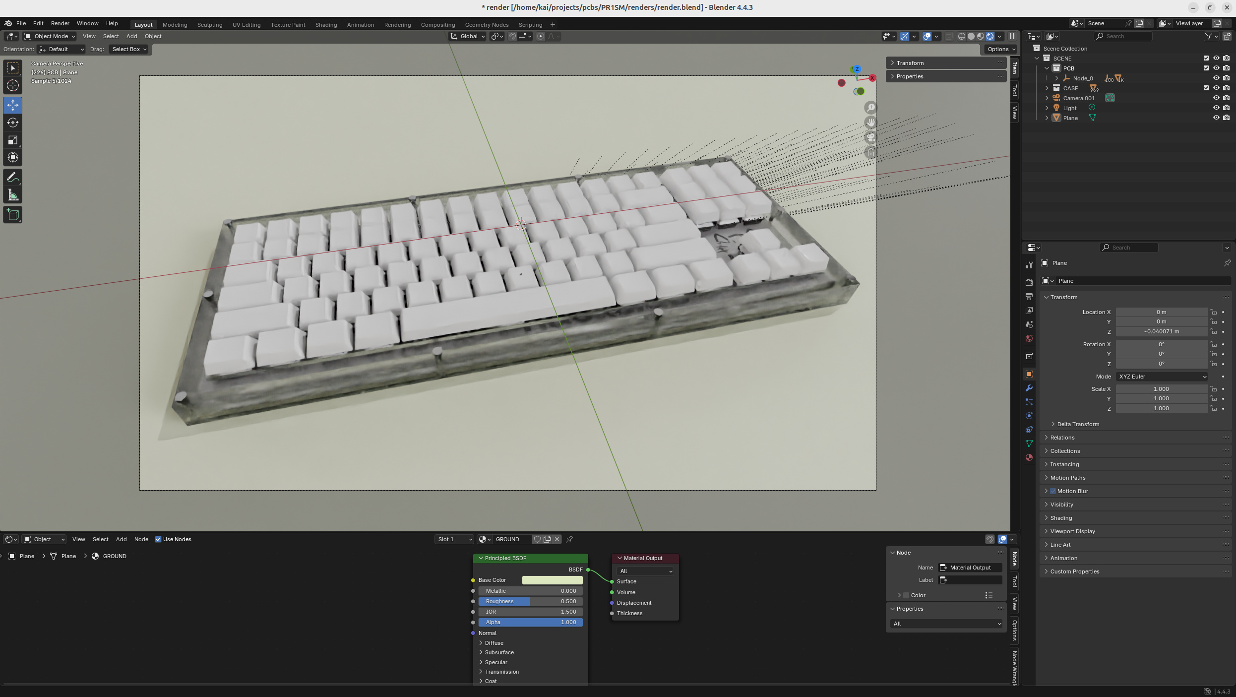
Also make sure to render with cycles instead of Eevee because it's way more realistic, and renders transparent materials like glass way more nicely.
Anyways now I'm going to actually render the image, and let's see how it turns out!
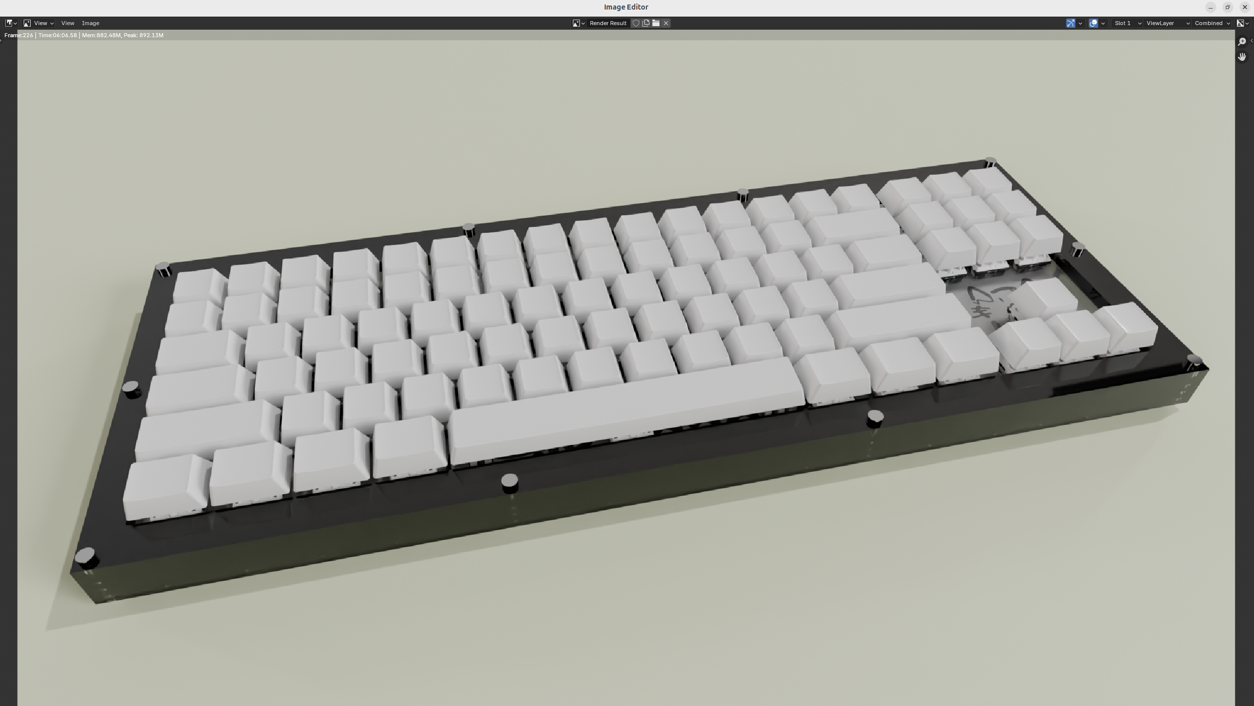
Now that looks pretty good, but I still want the acrylic to be kind of more see-through like the render preview, so I guess I'll have to mess around with the settings a bit more. But anyways I'm kind of too lazy to fix that, and now I just want to ship it out.
Maybe sometime I'll get it working, but for now, I'll just use the Onshape render because that one looks more realistic to the actual thing.
That was quite a bit of time wasted, but I did learn a ton more about Blender which was nice.
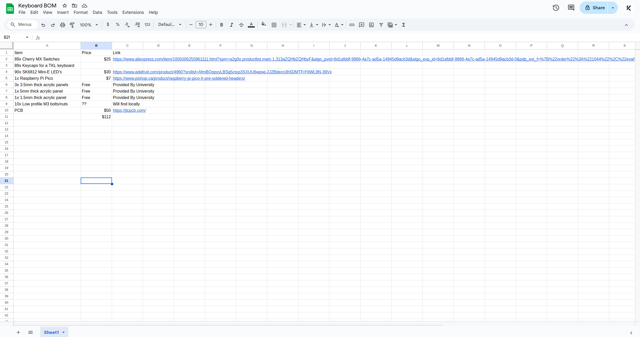
Anyways, finally, I created the BOM, and now it's time to submit!
Total time worked on this project: 23 hours (probably more than that, but this is a safe estimate)
Day 5 - Assembly - 10 Hours
I just got my PCB in the main and all the parts, so time to solder and assemble:
![[Pasted image 20250807051407.png]]
I had both neopixels, keys and diodes so it was going to be LOTS of soldering.
First I started off by tinning ALL the pads of my neopixels. This makes it easy for them to solder. But trust me, this isn't ACTUALLY the first thing I did, first I tried to solder them in directly which didn't work, so I did a bit of research and came across this.
Anyways, tin all your pads, and then place a neopixel on the pad. Hold the neopixel with tweezers or something and then just press the solder onto a pad and it'll join it in place. Now you can just do the same for all the other pads and then apply the solder when you're done for a nice finish!
Next I did the diodes, it was pretty simple, just some THT so I applied heat to all three, the pad, the lead and the solder, and I think my soldering turned out pretty nice.
![[Pasted image 20250807051322.png]]
I forgot to mention, but I had a pi pico, so I kind of just like soldered it THT, it already had pin headers so it was nothing crazy.
Anyways, after that, I put in all the switches, which was just quite a bit of solder used to fill the big pads, but it turned out nicely.
I didn't get my case in time so I actually couldn't do plate mounted, but I'll just switch the CAD design a tad so it'll work.
After doing all the switches, I put all the keycaps on, and it was looking beautiful!
![[Pasted image 20250807051506.png]]
Now all I had to do was upload the firmware which was just adding it from my repository and it was up and running!
Again, I couldn't have gotten the neopixels up and running in time before my vacation, but it's a functioning keyboard which I'm happy with!