
Total Time Spent: 43hr
July 4, 2025
I setup the layout using keyboard-layout-editor

Time Spent: 1hr
I created the basic layout of the keyswitches in the schematic after learning how matrixes work

... only to realize I need diodes.

Time Spent: 2hr
I wired up the matrix with labels

Time Spent: 1.5hr
The pico didn't have enough pins so I've begun work directly using the RP2040 using the RP2040 hardware design datasheet.

Time Spent 3hr
I finished up the setup for the RP2040 including power delivery, USB communications, and

Time Spent: 3.5 hr
I research JLC PCBA Extended and added all of the neopixels on a single pin that will draw 1.3A.

Time Spent: 1.5hr
July 5, 2025
I got a dark theme to stop searing my eyes and got capacitors for the NeoPixels, as well as having to figure out that 0.1uF is the same as 100nF.

Time Spent: 2hr
I found 0805 capacitors of varying capcity on LCSC, imported them using easyeda2kicad. I then assigned each type to its respective item, before realizing that the ESR of 0805 capacitors is too much for the RP2040 and that I would need 0402 alternatives. After going back to get the diodes, I couldn't find footprints so I had to slightly modify the template 0402 footprint.

Time Spent: 3.5hr
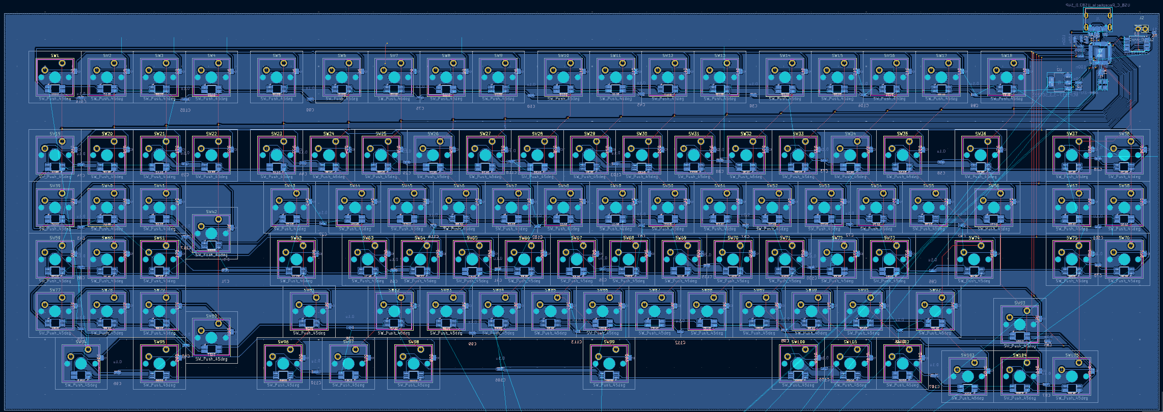
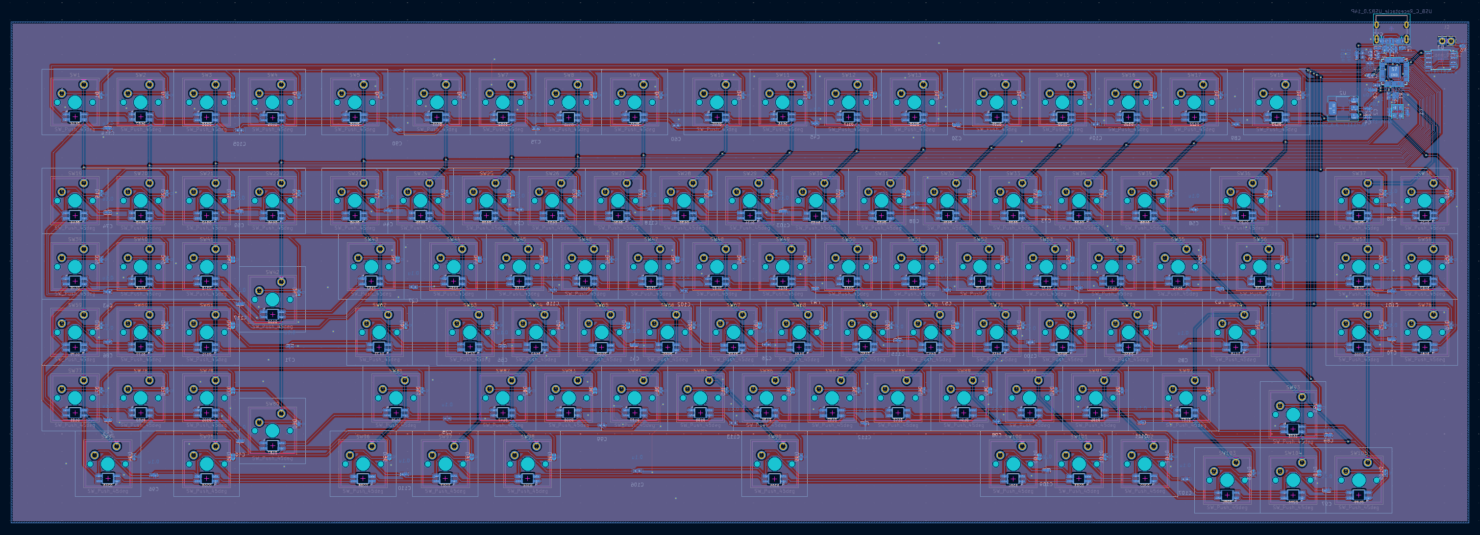
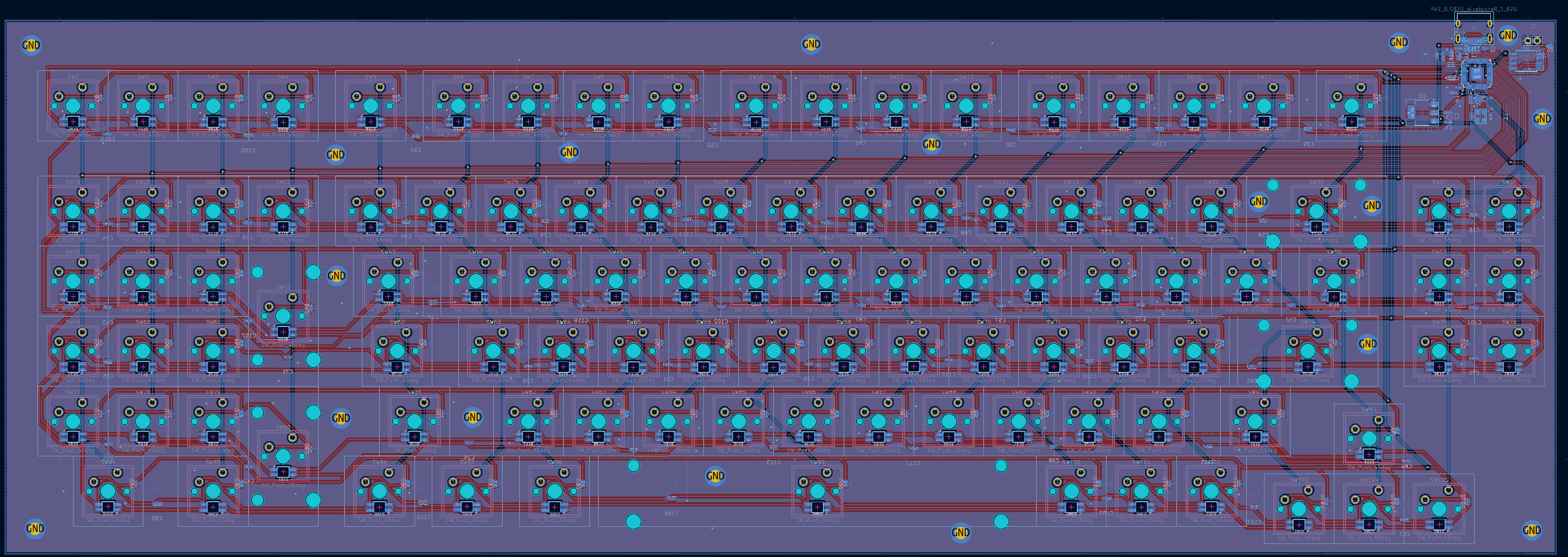
I started designing the PCB and started the grueling wiring of each individual key and light. I want to cry 😢. My fingers and my soul are in pain.

Time Spent: 2.5hr
I finished adding all of the neopixels, all 105 of them 😢.

Time Spent: 1.5hr
July 6, 2025
I added more capacitors as per the spec of the SK6812-MINI's... 52 of them. I love KiCAD 👍.

Time Spent: 1.5hr
July 25, 2025
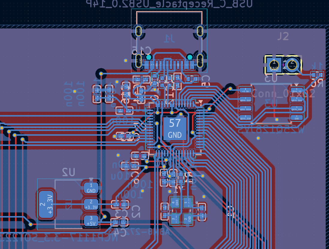
I started wiring everything to do with the microcontrollers and all of its additional parts. It got hectic and chaotic very quickly.
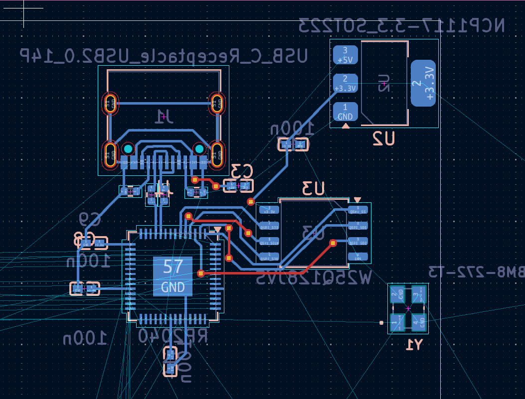
@marios recomended I do a ground pour so I used my hackpad v2 docs backup to learn how to do one and it started looking much better.
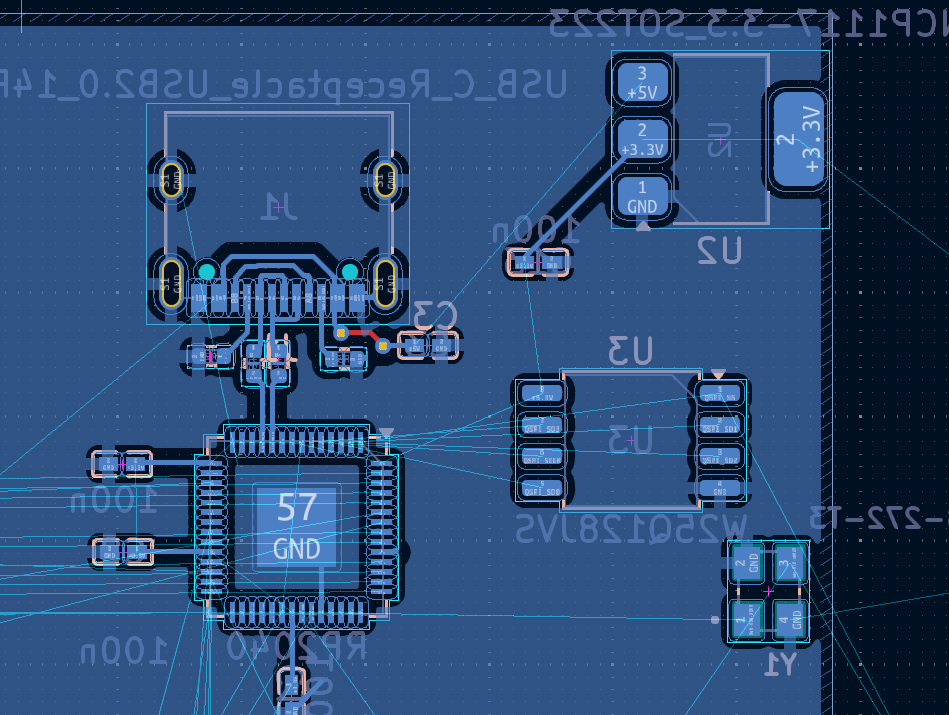
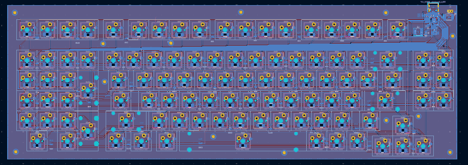
I then started on the rows and collumns, but was again having difficulty in figuring out how to route them without vias because they ruin signal integrity. Then I realized that the keys are binary and signal integrity/noise shouldn't be nearly enough to get to on from off. With that newfound knowledge, I routed all of them using at least 2 vias each.
Here's what the microcontroller section looks like:
Time Spent: 4.5 hr
July 26, 2025
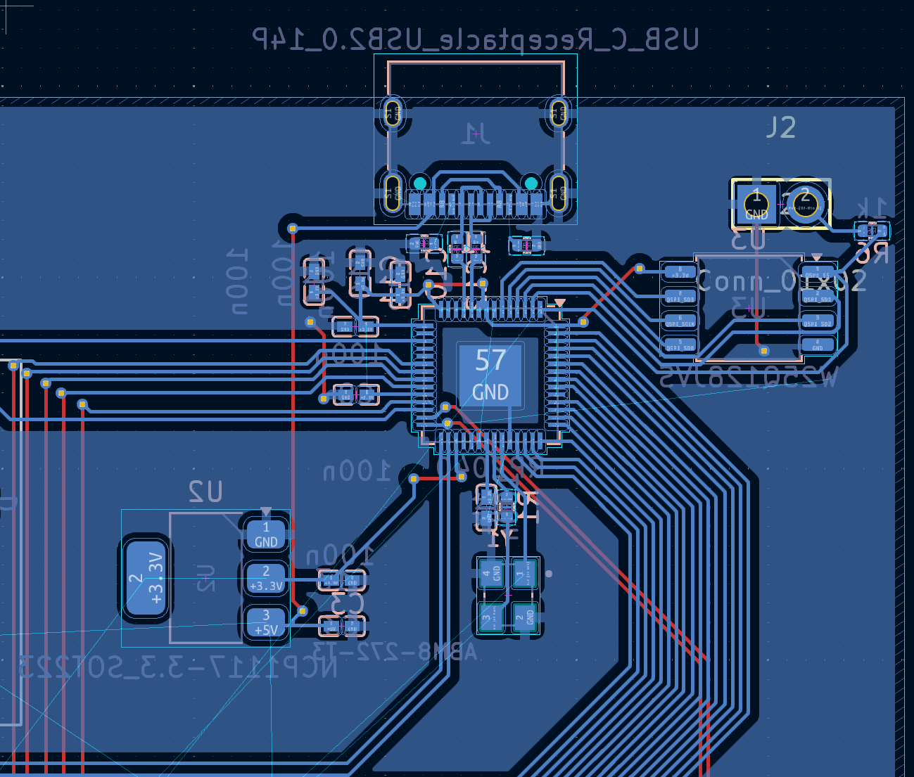
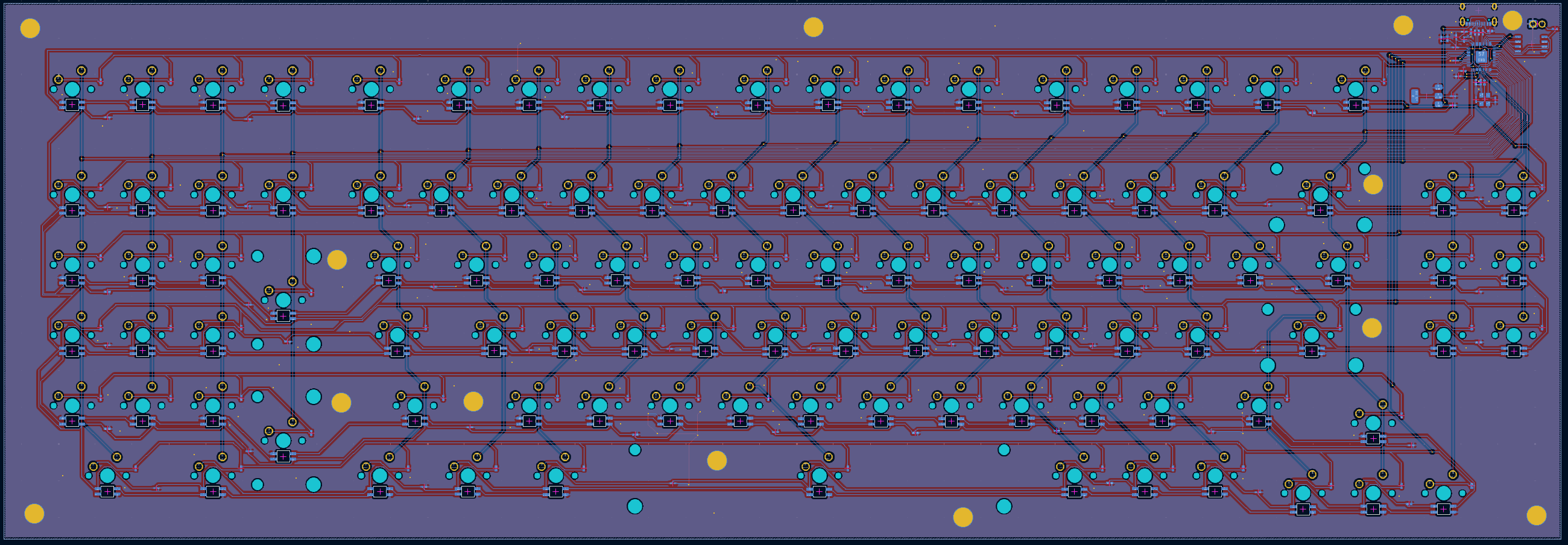
I finished the PCB!!!! 🎊🥳💃🎉📢📣 (almost, tomorrow I'll figure out the hole size I need for gasket mounting)
I did all of the requisite wiring and looked thorugh all of my DRC checkers to see if there was any major issues.
As per @mra's suggestion, I set the ground fill to both sides and put in a bunch of vias to connect all of the unconnected areas (that I had to constantly change to no layers to check where the unconnected areas were).
I now have 0 unconnected areas, except for the sides of my heart, which is now broken after spending so much time on a keyboard that might not work.
I also had to add a few more decoupling capacitors as per the spec, which, as always, required a lot of rerouting.
Time Spent: 3.5hr
July 27, 2025
I finished the mounting holes and added holes for stabalizers. Originally I wanted to forego using screws and wanted to do a gasket mounting setup, but with cost quickly becoming something I have to look out for, I'll leave the mounting holes, and get poron foam to laser cut at my local library should there be room in the budget.
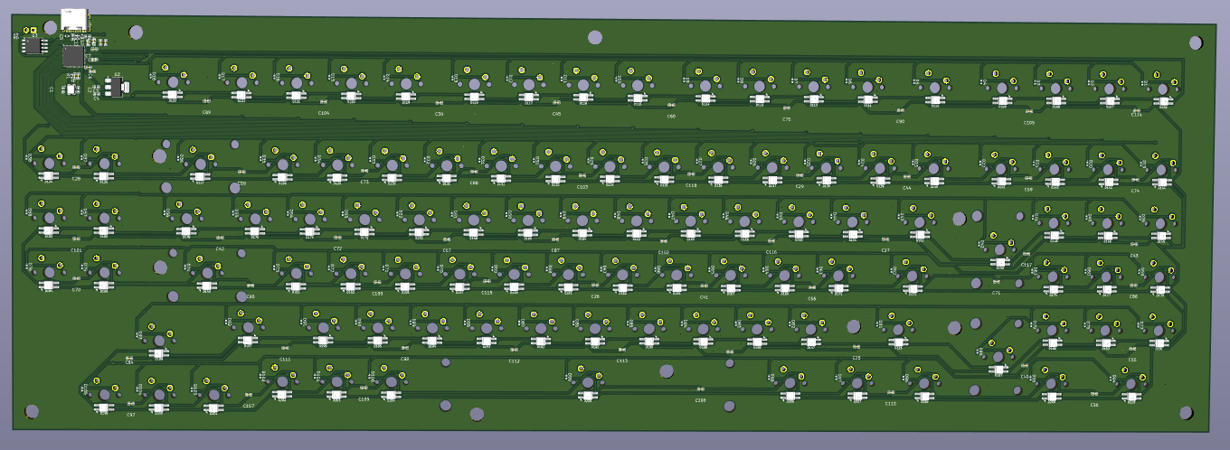
Time Spent: 1hr
July 29, 2025
I added some more mounting holes and altered the size to be much better matched to the actual size of m3 screws.
I also began CAD and started trying to figure out how to add a plate for my switches.
Time Spent: 1.5hr
The holes were intersecting the stabalizers so I changed the position which required redoing half of the work I did.
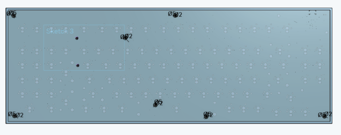
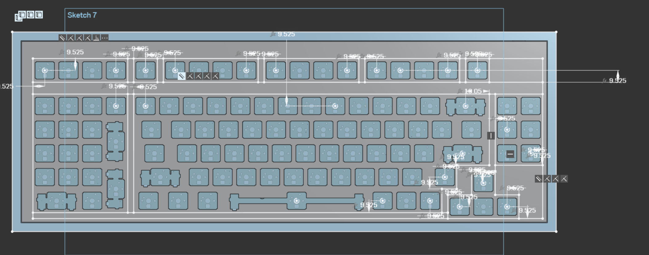
While I was working on that, I decided to go and switch the measurements to variables to allow me to change them en mas later if tolerances don't allow.
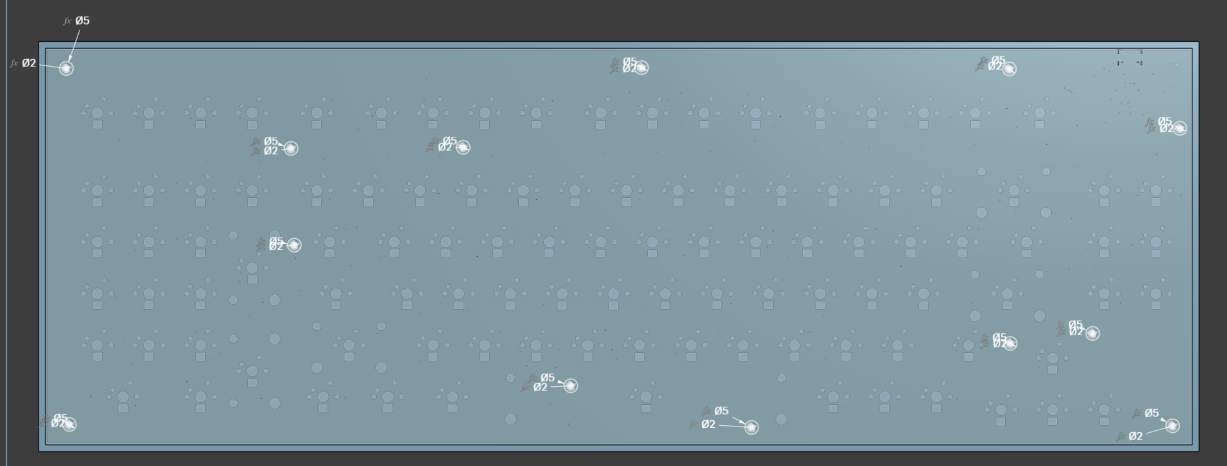
The grey 𝑓𝑥
indicates they are calculated instead of a set variable.
Time Spent: 2hr
July 30, 2025
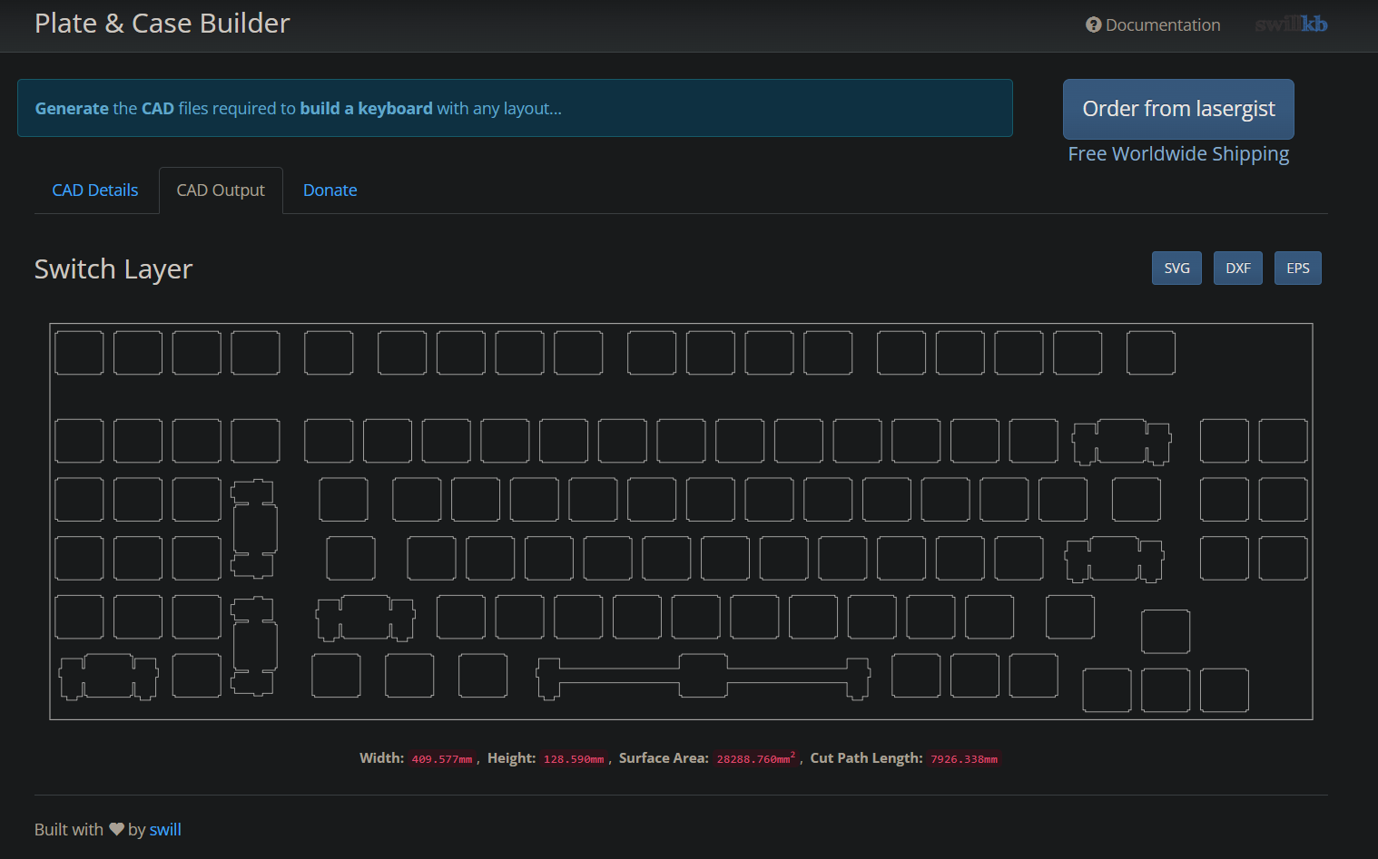
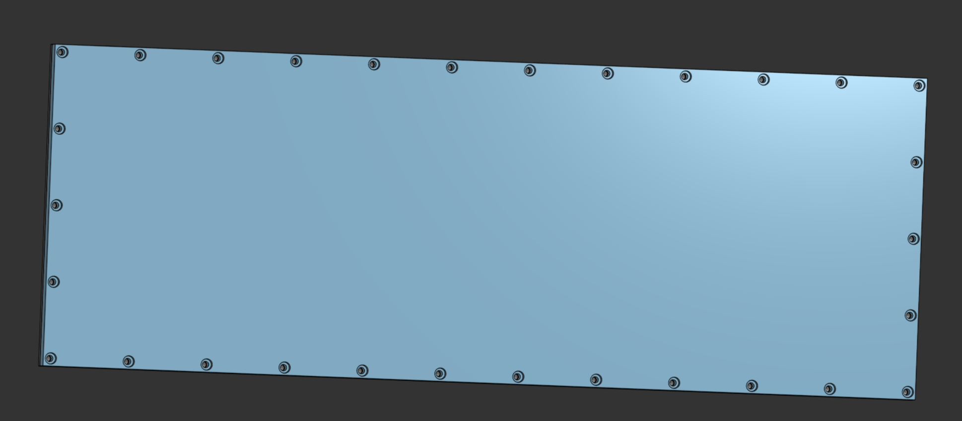
I looked at Joe Scotto's How to Design Mechanical Keyboard Plates and Cases as reccomended by the hackpad guide, and got a DXF of my keyboard layout.
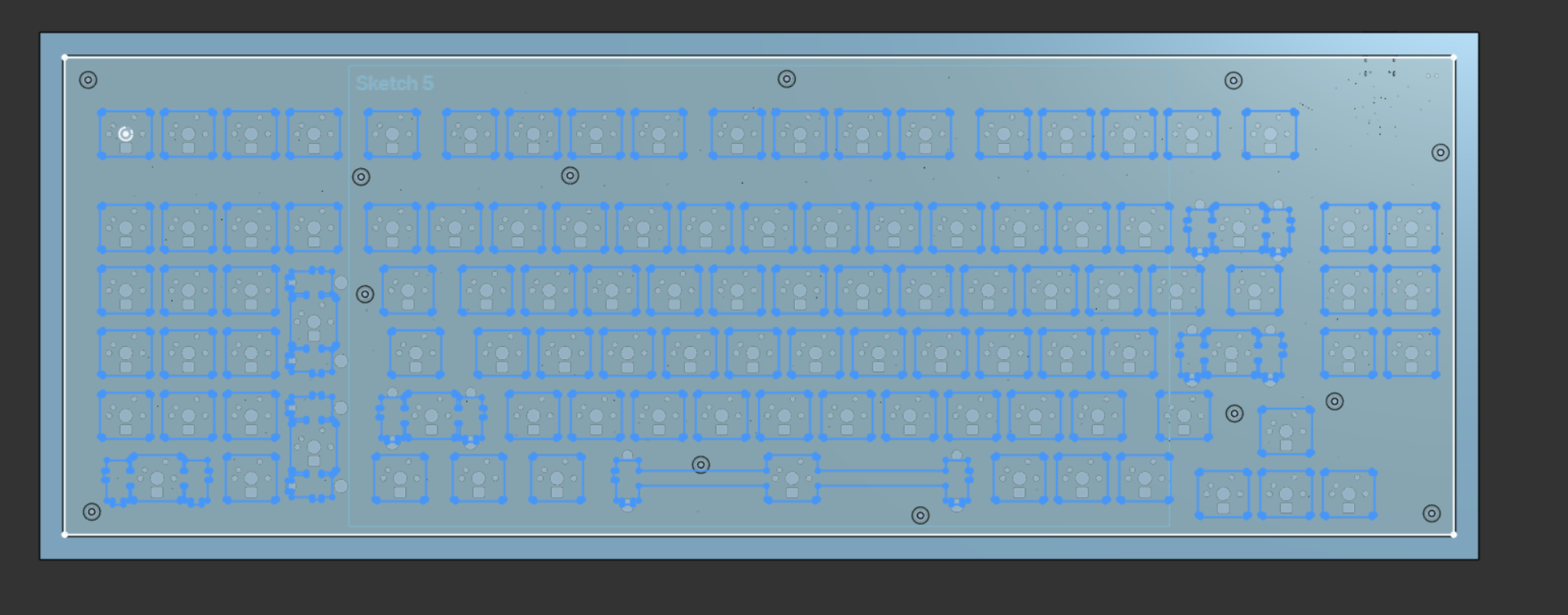
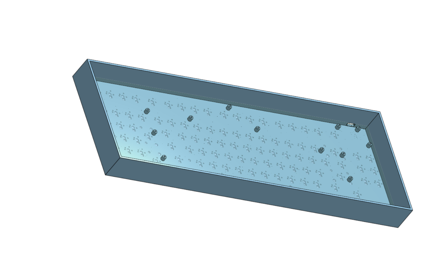
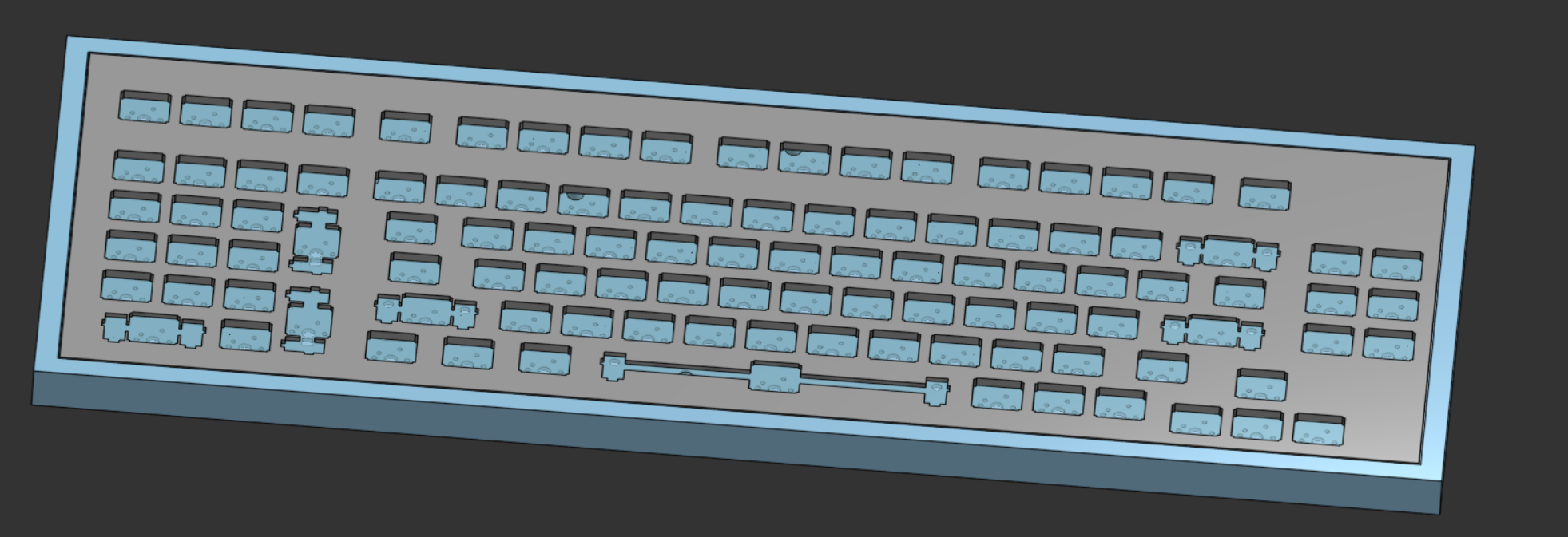
Here's what extruding that plate gave me:
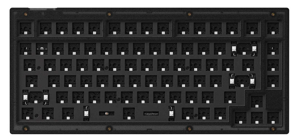
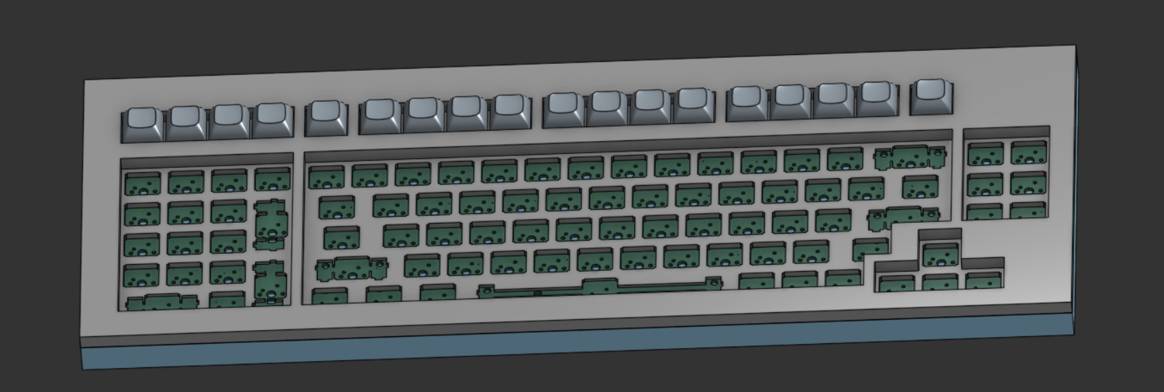
After that, I went and looked at this Keychron V1 product image and realized that there was the elevated sections where the weren't any surrounding keys.
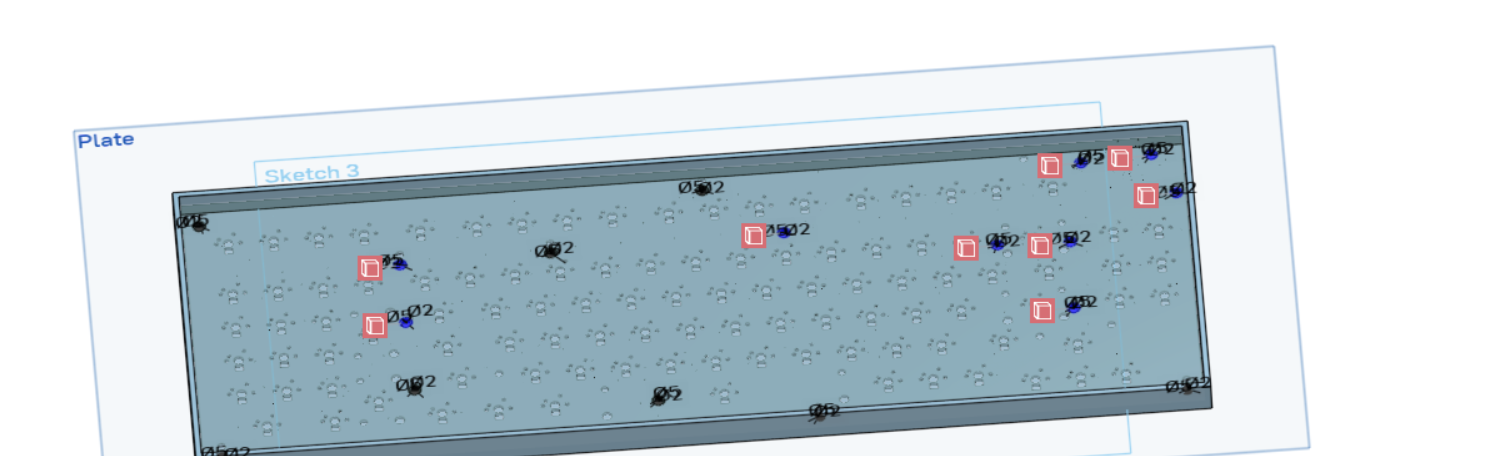
So I sketched out all of the areas where the weren't any keys and dimensioned them using dimensions I found on this datasheet on Google Drive.
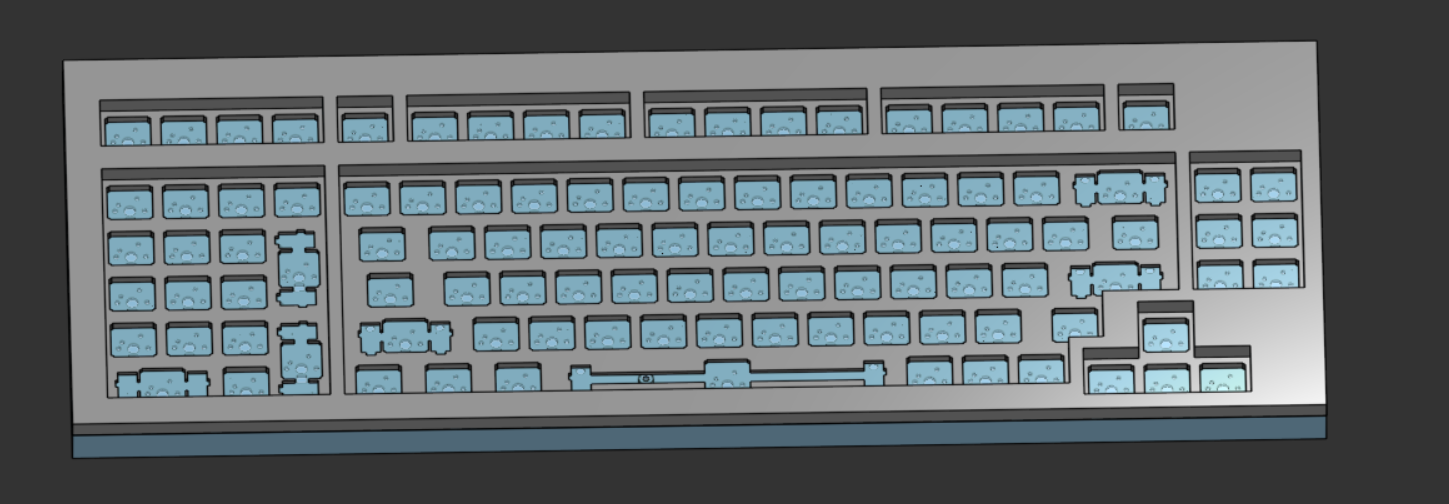
Here's what it looks like as a unit.
Then I added some mounting screw holes with a counterbore so the screw head wouldn't stick out.
Time Spent: 2.5hr
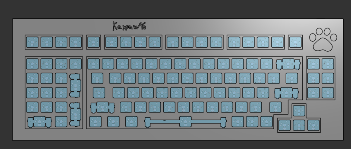
I added each switch (one by one) into Onshape so I could have a full render.
First with the function row
Then with the numpad:
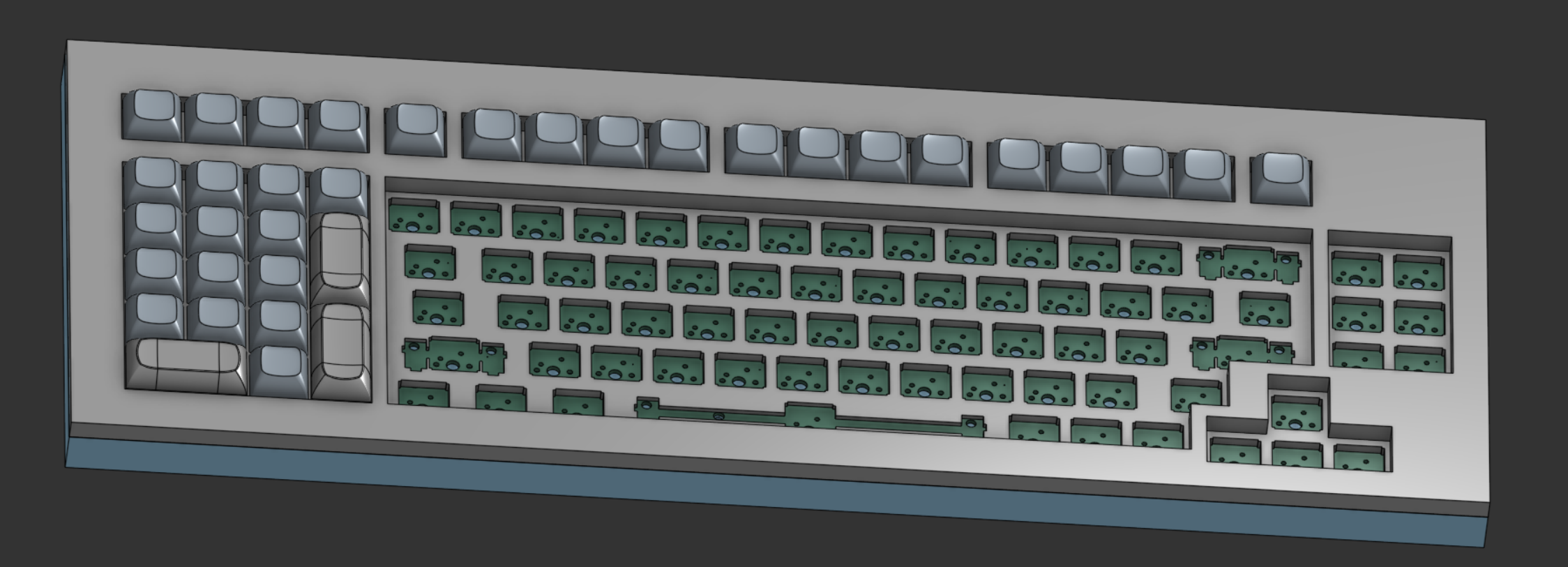
and then just idk general area
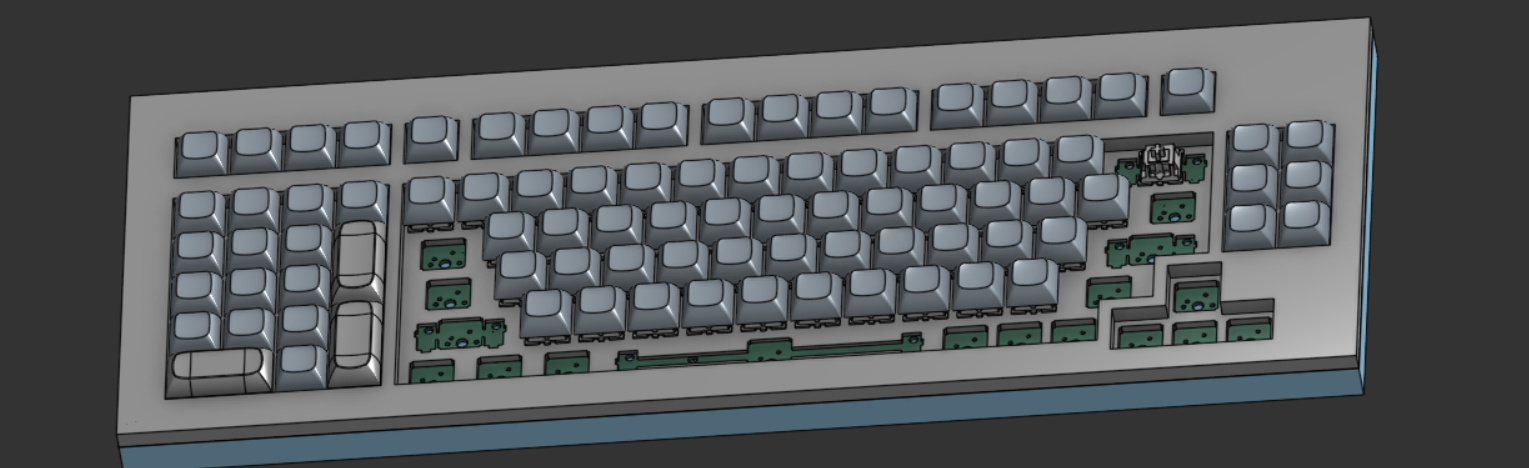
Here's the fully setup:
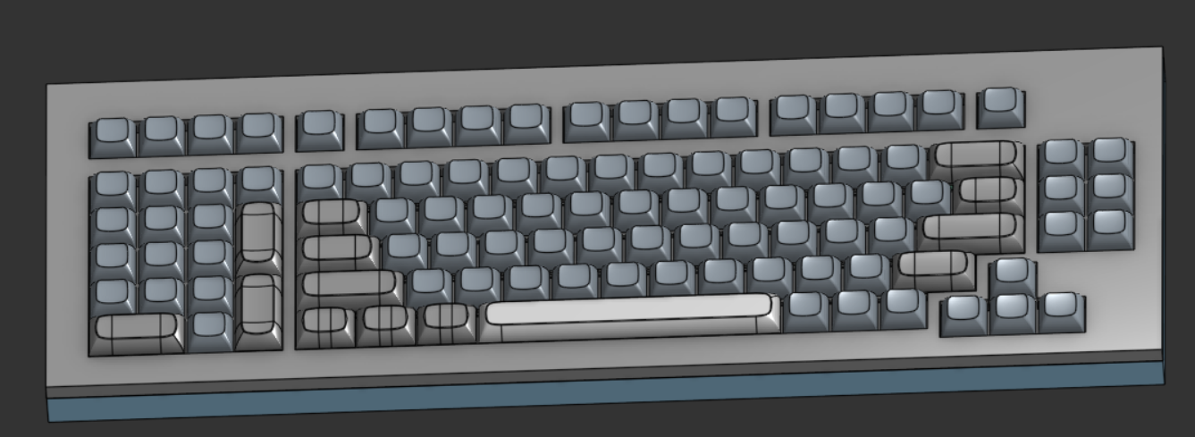
(The different colors are from pulling the keycap models from different places.)
Time Spent: 2hr
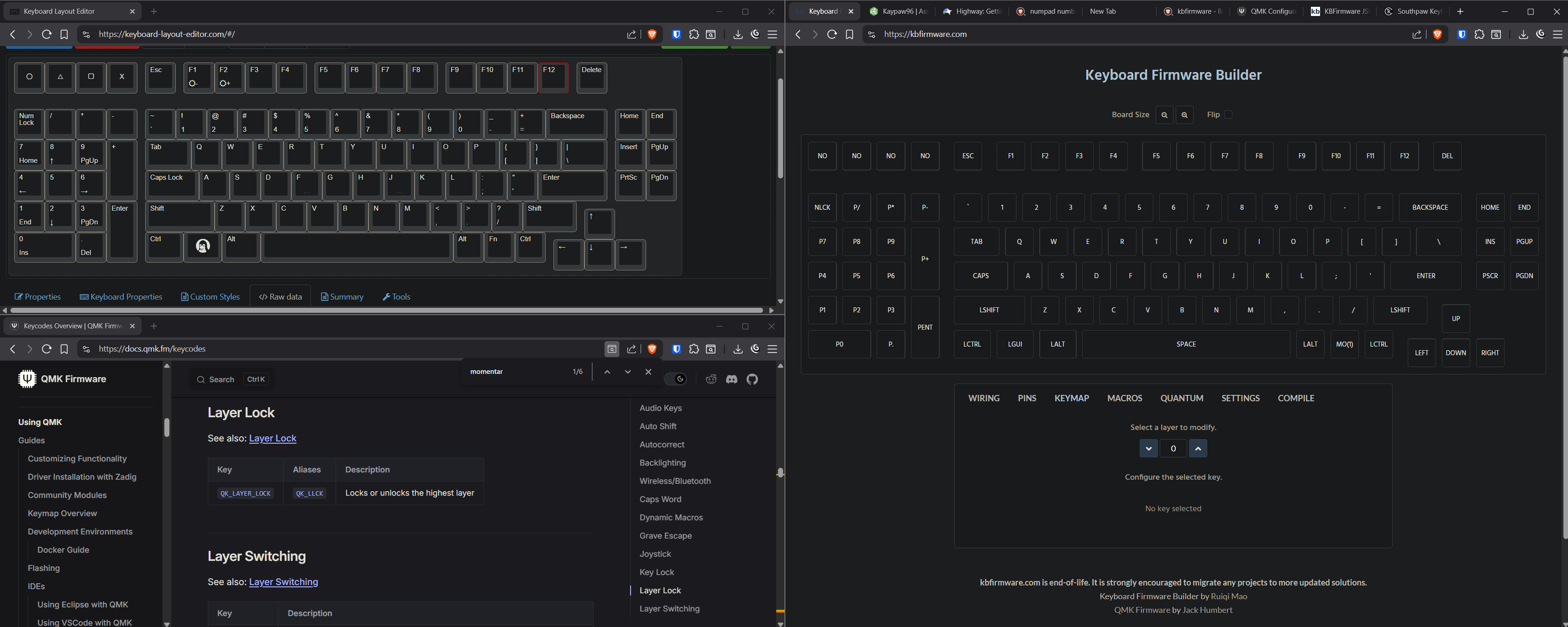
I saw this video that told me to use kbfirmware.com, so I imported my layout into it.
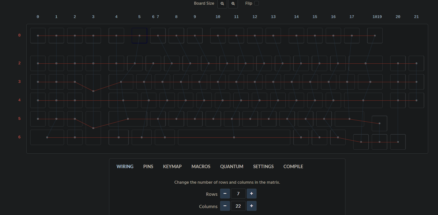
It did not import correctly at all, wrong number of cols and rows and some stuff isn't routed to the right place. Since you can't do bulk operations, I'll have to do something that's becoming something of a trend on this keyboard and do it one by one.
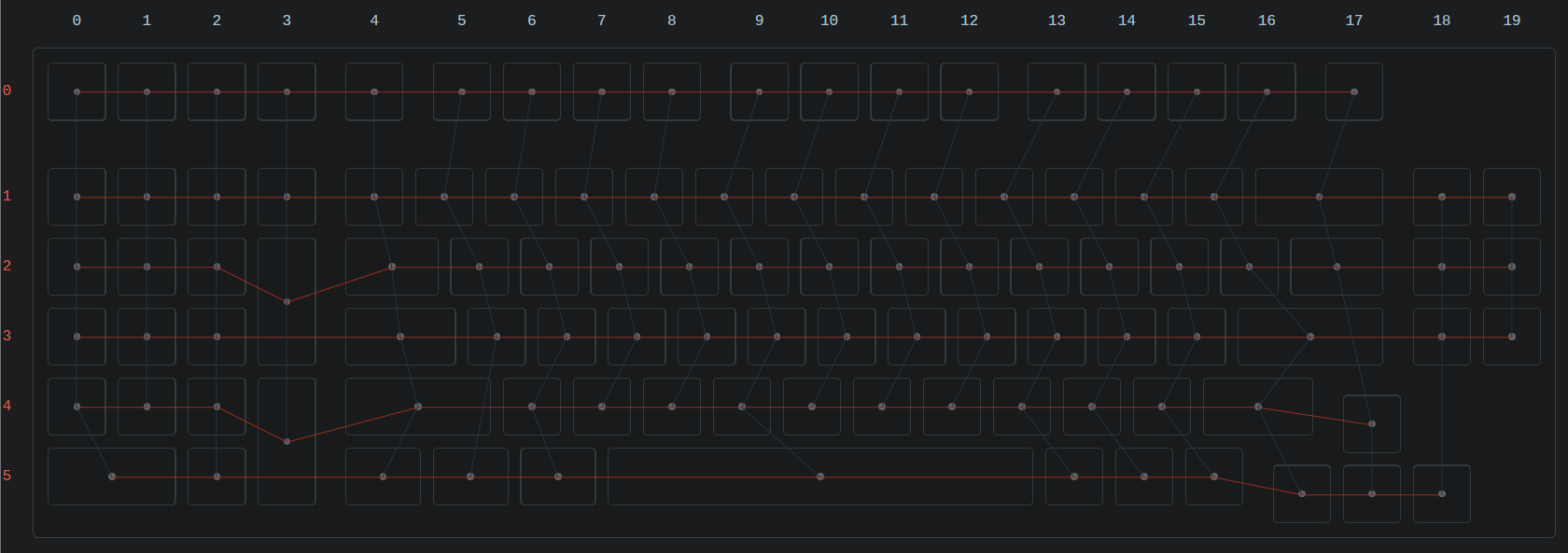
I then moved on to the keymap phase. The QMK Keycode Docs were super easy to use and quite helpful.
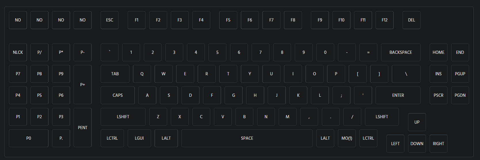
The task took so time but this work layout made it so much more efficient to work on.
Time Spent: 1.5hr
July 31, 2025
I went and did some light customization to really make this keyboard my own, including a logo made in MS paint:

Time Spent: 1hr