
Robodog
Total Time: 28hrs
June 11th-12th: Fully CADed
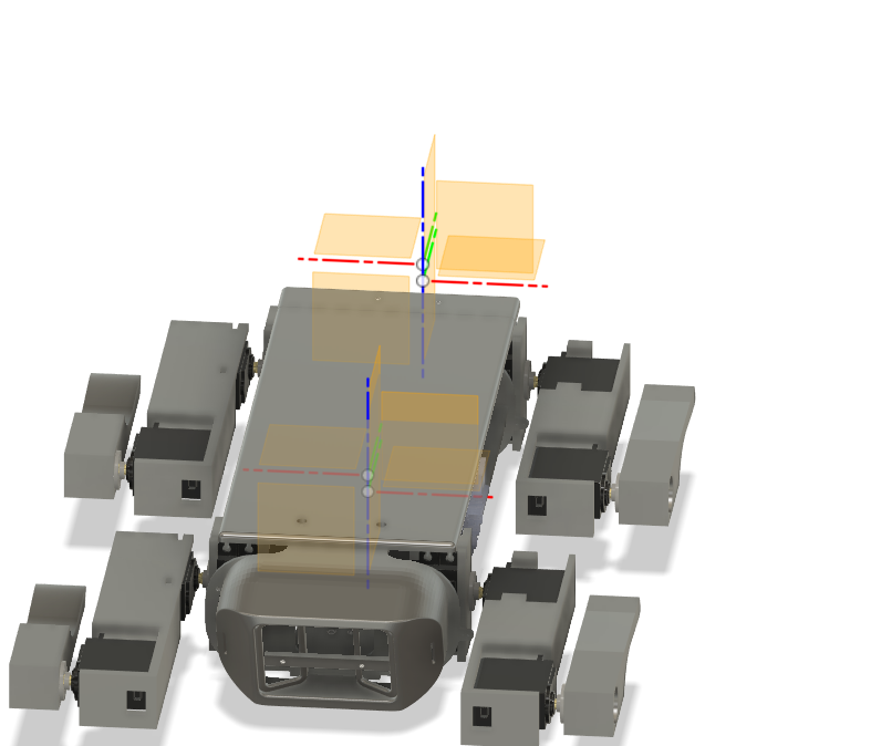
Started off the project by launching Fusion 360 and blocking out the dog's main chassis. My main goal here was functional simplicity — something that’s easy to assemble, modify, and mount hardware on without disassembling half the bot every time i want to add/remove something.
The design I landed on has:
- A flat center plate that acts as the main body, made wide enough to comfortably hold the Pi, power distribution boards, battery, GPS, and (hopefully) a lidar
- Two rounded end plates — just simple ovals that hold the servo brackets in place for each leg. These are symmetric and bolt straight onto the side of the center plate
- Leg brackets aligned vertically to simplify the IK — each leg has a clean coordinate frame, and the coxa (hip) servo only rotates in one axis
The whole CAD is parametric, so I can tweak servo spacing or leg lengths later without rebuilding everything.
For now, I decided not to CAD any decorative shells or aesthetic casings — this robot is going to get opened and torn apart regularly as I iterate.
The legs themselves are 3DOF, made up of:
- Coxa (horizontal rotation)
- Femur (up/down swing)
- Tibia (final linkage)
I'm using MG996R servos for all joints. They’re not ideal — big dead zones, analog feedback, and can burn out under load — but for their price and torque (~10kg-cm), they’re a solid starting point for a dev platform.
At this point, I’m happy with the mechanical design — but it took way longer than expected (I’m 3 redbulls deep and fully aware that I should’ve sketched this on paper first, but I cannot draw).
Time Spent: 15hrs
June 13th - Schematic
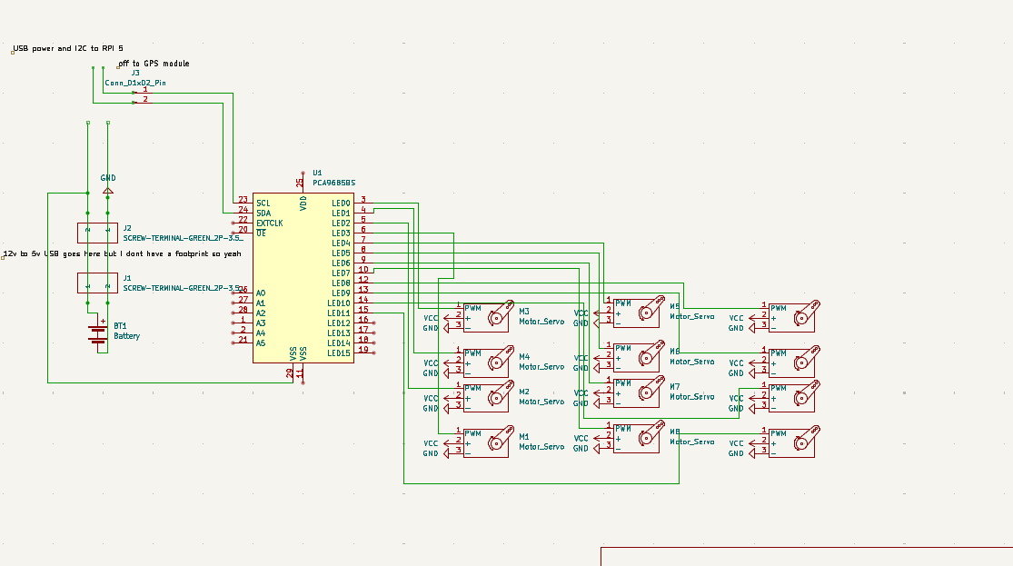
Did the full schematic layout for wiring everything together.
The build doesn’t use a custom PCB (at least not yet), so this schematic was mostly to organize:
- 12x MG996R servos (3 per leg)
- 1x PCA9685 servo driver
- Pi 4 power via USB boost board
- GPS module via UART
- Optional second PCA driver for expansion
Used the schematic as a build reference, mainly so I don’t fry something expensive.
Time Spent: 2hr
June 14th - Firmware Pt1
Finally jumped into the firmware side — specifically the inverse kinematics (IK) solver.
I started with basic 2D planar IK just to get a feel for how the math works. Then gradually added complexity:
- Each leg is modeled as a 3-link manipulator
- The joints are offset in real 3D space but constrained to operate on a 2D plane per leg
- Used basic trigonometry — cosine law, sine law — to solve for femur and tibia angles
- The coxa joint is just a simple
atan2(y, x)to find the rotation from the robot’s center to the leg’s target
The trickiest bit was solving for reachable vs. unreachable points — since these are cheap servos, they can't actually hold position reliably under tension. So I added a soft clamping system that limits paw positions to a safe working volume per leg.
Once the math was stable, I built a standalone Python test script that:
- Lets you type in an XYZ paw coordinate
- Solves and visualizes the joint angles
- Outputs the result in degrees, ready to be piped to the servo driver later
Also added some forward kinematics functions so I can sanity-check the solved angles (and catch bugs in weird limb configs).
Next: wrap this math in a ROS node.
Time Spent: 5hr
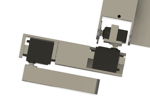
June 17th - Updated CAD and Finished Firmware
Added a lid! The barebones open-top chassis was good for dev, but I was worried about connector damage or shorting stuff on the metal servo cases. So: added a snap-on lid.
Finished the Python-based firmware:
- IK engine is now stable and modular
- It supports per-leg calibration offsets
- Outputs angle commands in degrees (for PCA9685)
Next step: slap it into ROS.
Also, I decided against using a PCB because of one simple reason: cost
If I were to make a PCB, i could make two different ones for two different purposes
- One could be a power distribution PCB with the XY3006, just with an XT60 input but with PCBA costs and import duties, a 150 rupee xy3006 board + a cheap XT60 plug to wire thing looks much better in front of a 5k+ PCBA(not even including the 100%+ import duties(thanks, nirmala))
- Another one could be a PCA9685 carrier board with an I2C multiplexer but honestly I can slap both of those together for 15-20x cheaper because yet again(lets say it together), our lord and saviour, nirmala sitaraman
I do understand the point of highway is for us to do things like this but honestly it just seems irresponsible, and I think my project will have enough complexity with the ROS stuff coming up
Time Spent: 4hr
June 17th-18th - ROS TIME BAYBEEEEEEEEEEE!
Wrapped up the ROS2 workspace! This was the big milestone. The whole project is now structured as 4 packages:
servo_driver
The hardware abstraction layer.
Written in rclpy, this node:
- Talks to one (or two) PCA9685 servo drivers via I2C
- Receives joint angle commands (in radians or degrees)
- Publishes current servo state (mostly for debugging)
- Has a watchdog system to stop movement if no command received
It exposes:
/set_joint_angleservice (per joint)/set_leg_posetopic (batch commands per leg)- Optional
/enable_torquetoggle
leg_walker
This is the brain of the walking system. It:
- Handles IK calculations per leg
- Has a gait generator (currently trot, more coming)
- Coordinates paw trajectories using phase offsets and timing
- Publishes joint angles to
servo_driver - Includes a
walk_controllernode to send commands likewalk_forward(speed)orrotate_left(angle)
Uses a parameterized robot.yaml config to define joint lengths, servo orientations, and bounds.
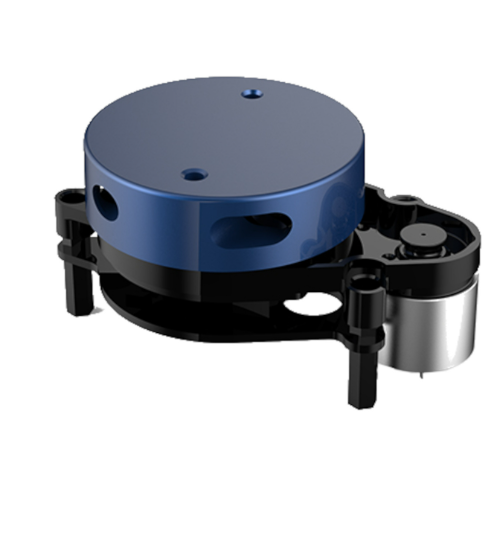
slamyplidarx2
Runs 2D SLAM using a YDLidar X2 sensor.
Launches:
ydlidar_ros2_driver(reads Lidar via serial)slam_toolbox(in synchronous mode)- Static transforms to
/base_link - RViz with a custom config
Map is built in real-time and saved to a .pgm+.yaml pair. Robot pose is published on /slam_pose.
slamstereopicams
Alternate 3D SLAM method using two Raspberry Pi cameras as a stereo pair (synchronized via GPIO).
Still very much a WIP, but:
- Captures stereo image streams using
picamera2 - Uses OpenCV stereo depth maps (SGM block matcher)
- Optionally feeds depth + RGB into
rtabmap_ros - Will be used for outdoor SLAM and low-light mapping
This branch will probably get moved to a Jetson board for performance.
Time Spent: 2hr