
June 1, 2025
So, i decided to build a PCB hotplate. Yes i had decided to make it before it was put up as ideas on highway website.
Yeah so i am gonna start a bit of research. What i think i need is that first of all a controller(I think i am gonna use the OG RP2040), then i need a mosfet which can handle high current, i would need a voltage regulator for the RP2040, and i would need copper tracks and i would need a thermistor or a temperature sensor.
Okay, this is the mosfet i decided to go with. This is the voltage regulator i decided. Can't find a good thermistor now i'll look tomorrow.
GUESS WHO FOUND A GOOD THERMISTOR IN JUST A FEW MINUTES AFTER THE LAST COMMIT BECAUSE I COULDN'T WAIT TILL TOMORROW
Time Spent: 30 mins
June 3 2025
Couldn't work yesterday cuz i had to study, and now started the journal again cuz i realised that the old mosfet is not compatible with 3.3v from rp2040. so i changed the mosfet and this is the new mosfet now. I will be controlling it using PWM.
And um yeah i also wanted to tell that i will be using thermistor for calculating temperature of the plate. this will be done using a voltage divider network, probably a 10k ohm resistor connected to ground and other side connected to thermistor and thermistor connected to 3.3v, and the voltage divider junction will be connected to rp2040 to measure temperature.
I will be using a similar technique to measure the input voltage, like i can use a resistor divider to measure voltage which will thus help in controlling MOSFET. Probably gonna use PID.
That's all for now
Time spent this session: 10 mins
Um Okay, i forgot to mention this, but i am also gonna use an OLED, and two buttons (Push button), i wanna make it like pinecil....
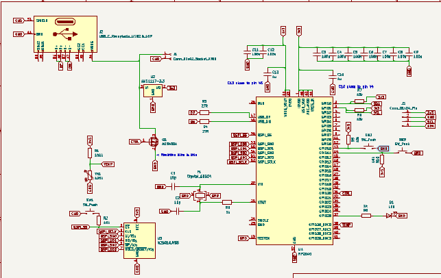
Okay, i think most of the things are done in the schematic, here it is(btw i assigned a few footprints too):
Btw what i was thinking is that PID would be
overkill for this, i think a normal algorithm
(PID minus ID, means only proportional) would be
0K. But i am going to try PID too!!
And Somehow i have to find a way to figure out
the resistance of the Big PCB trace, and i
thought of going with 5cm x 6cm PCB trace Area,
and i will try to make the whole board in 6.5cm
x 6.5cm...
Total Time Spent Today: 2 hours 10 mins
June 5 2025
It's 4:30 AM. Gonna start working on the project, i am in the call right now.
I need a current sensor to Measure the current going through the coil. So, this is the current sensor i found.
Curent Sensor changed. Current Current sensor is the TI INA226
Okay, i worked on the schematic a bit, and now i will probably start with the PCB.
Completed the schematic:


Total Time Spent This session(the call): 2 hours 30 mins
I dont think i am gonna work anymore today so here is the total time spent today(i am really tired as the call was at 4:30 AM for me, i had to wake up way early(4 hours early than usual))