
Meko Music Player
A high definition music player with bluetooth support, which has an e paper display and a physical wheel
Total time ≈ 87h
04.29: chose the soc, and usb uart switchin
- choose the esp32-mini-1u because it has support for bluetooth audio and rust
- this chip doesn't have an integrated usb controller, so I had to choose a chip for usb to uart
Total time: 1.5
05.05: added the dac/amp chip, added display connector
- there is little info on high quality dac/amp chips, after many days of research and pain a choose the ES9218P, which is a really nice chip to work with, but the datasheet is a bit lackluster
- chose a display, added the flex pcb connector for it
Total time: 2h
05.07: added the hall-effect sensor for the wheel
- I saw a wide where a guy made a high precision scrolling device, and he used a hall-effect sensor, I chose to go down this rout because there is no rotory encoder to ware out
Total time: 1h
05.08: power, lil bit
Copy pasted bms and power path chip from previous project, did some calculations, changed resistor values
Total time:1h
05.09: power and usb
Chose a dual output switching regulator, implemented usb to uart chip
Total time: 1.5h
05.10: audio
- Read the datasheet far more times than i would like to admit
- Some things are not clear
- implemented the things that I kinda understand
- asked a question on stackexchange

**Total time: 1.5h**
05.17: some Chad replied to my question on electronics stackexchange
- Someone who has experience with this rare chip, YIPPPEEEEEE
- I will have to use a oscillator, not a crystal, and low noise LDOs instead of switching regulators
- Did some research on mems vs oscillator vs crystal

**Total time: 2h**
05.18: implemented to suggestion from stackexchange
- oscillator instead of crystal
added low noise LDOs
Total time: 2h
05.22: Added components, choose LDOs
- I switched from a esp32-mini-1u to a esp32-pico-mini-02, for an integrated pcb antenna and a smaller from factor
- Chose the micro SD slot, and added it to to the schematic
- the same chad from electronics stackexchange replied to my other question about power delivery for this chip
Did a lot of datasheet reading abot LDOs and what to choose, and decided that will try to solder 1mm*1mm packages
Total time: 3h
05.23: Power, power, POWER
- implemented the LDOs
- learned a lot about filters, low-pass, high-pass, etc. Interesting topic
again lots of reaiding
Total time: 4h
05.24: inter chip COM
- the esp32 has a f#$* up io multiplexer if you want to do multiple things
- the SD card pins and the JTAG pins are the same, so if you use an SD card you cant use JTAG, or vice-versa
- all of the pins that can output a i2s clock signal are used by uart or the boot pin
- might need to figure something out for using the same pins for different things
- wired up the hall-effect sensor, en and boot pins with the usb-to-uart adapter, some parts of the dac/amp chip, SD card
- created a symbol for my display
read a bunch again
Total time:5h
05.25: finishing up the schematic
- finished display, aka copied reference design
- turns out you can you can use gpio0 as a regular gpio0, you just need to make sure that it doesn't get pulled low on boot, so my i2s clock is on gpio0 (aka the BOOT pin)
- chose the headphone jack, and added the footprint and 3d model
- still need to add esd protection in some places
- added buttons
- routed spi for the display, added test points
- i dont have enough gpio to controll the DACs power chips, so they will all start up at once, which is not optimal, but....
i need to connect up the headphone jack
Total time: 3h
05.25: I'M ALMOST DONE WITH THE SCHEMATIC
- added an I/O expander, because i ran out of I/O
- added led, and haptic motor
- since i added a io expander now i can control the boot sequence of the dac/amp
- added more esd protection
- researched how inline volume controls work
segmented schmatic
Total time: 4h
05.28: fixing
- fixed vibartion motor, made schematic more organized
added leds, jack, and esd
Total time: 1h
05.29: fixed stuff
- removed separate i2c line for the dac, becouse i needed one more gpio for the a ldo enable pin
changed pull up resistor values on the i2c line
Total time:0.75h
05.30: added fuel gauge, 3d models
- fixed small ERC issues
- realised that i have no way to check the battery percentage
- added a fuel gauge ic
- realised that the ic that i have chosen has the same i2c address as the hall encoder
- chose another ic, this is bga, but only 3x3 so its not that bad
- added all the missing 3d models
ready for layout
Total time: 3h
 |
 |
 |
 |
05.31: starting layout
- realised that i still need to chose the battery connector, i went with PH2.0
- changed footprint of sk6805
started the layout, it is kinda hard
Total time:2h
06.01: mockup
- made a mockup

- arranged the display and the hall sensor based on the mockup
- decided to fold the flex display cable, because i had no space for the hall sensor, luckily my connector has contacts on both sides
- i have to reorder the pins, because of the folding on the flex connector
reordered the pins
Total time: 2h
06.02: layout is like a puzzle with multiple correct solutions
- arranged the jack and power button based on the mockup
- laid out the dac/amp chip
added charging led, so you know if you are charging your player
Total time: 1h
06.03: more layout
- arranged the button pull ups and caps
- moved around the dac/amp
- laid out power
laid out some parts of display
Total time: 4h
06.05: finished with the layout, almost
- realized that the BOOT pin shouldn't be pulled down, but because that way it is booted into firmware mode, so i pulled it up with a 100k resistor, so it doesn't interfere with the i2s that much
- laid out most of the components, some placements are not final, because they will depend on the routing
- moved the via fence around a bit


**Total time: 2h**
06.06: routing started
routed most of the important circuits, like the usb lines and the i2s lines
Total time: 1h
06.07: maybe chose a too small pcb size
- I'm starting to have trouble routing some tracks, I may have made an oopsie
- routed the short tracks, kind of a grind
- finished the routing, time to send it of to reddit


**Total time:3h**
06.10: fixed fuel gauge
- some chad redditor saw that i had connected my fuel gauge IC wrong, i connected SRX to the output of the batter charger, instead of connecting SRX to the batter input of the batter charger

**Total time: 1h**
06.11: small fixes, moved stuff around
- flipped buttons, cuz it didnt make sense to have them on the other side
- added vias to the bottom pad of the dac, forgot about them
- other small fixes
selected some components based on the value in the schematic
Total time: 3h
06.12: picked MPNs, stiching VIAs, 3d modeling
- choose MPNs based on the footprints and values
- added stiching VIAs
- imported the bearing 3d model that i want to use
- started modeling the e ink display, and real realised that the connector i chose for it is for 1mm thich FPCs, and the cable on the display is 0.3mm
- i have to choose a new connector
- turns out, 1mm, is the height of the connector and not the cable, so im fine, panic over hhuuhhh
Total time: 3h
06.13: CAAAD, fixes
- chose a 6701 bearing
- moved buttons and mounting holes around to make space for it
- moved jack out to board edge, because it had interfered with the pcb
Total time:3h
06.14: CAAAAAAAAAAAAAAD
- done with the bottom part of the case, mostly
- the top part is also almost done
- moved stuff around on the pcb to make the device more thin
- player is still 16 mm thich
- choose battery
Total time: 4h
06.17: Almost finished with the case
- I was wrong about the to part almost being done
- added holes to the top case for the threaded inserts that i will glue in
- added a rim to the top case so when i tighten the screws this rim will be the main contact point with the pcb
- added a stopper to the bearing hole, so that it will sit at known hight, and not at some random hight in the hole, also prevents the bearing from touching some components
- figured out how to keep the display in place, will model it later
- adding some images, I havent done this in a while, i might have to back journal, and add some more, cuz this journal is basically a wall of text


Total time: 3h
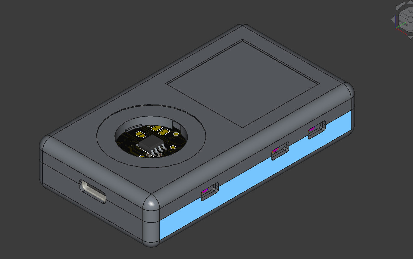
06.18: finished cad
- Finished display retainer, it's like a plate that is held down by the pcb

- modeled the button
- I found a way to make it thinner, firstly buy leaving the battery less wiggle room, and a cutout for the battery in the case, this will reduce the thickness by like 2mm, so it will be around 13,5mm
- choose the magnet for that hall-effect rotation encoder, here is the link
Total time: 4h
06.19: rounded tracks, cad assembly
- created a cad assembly

- modeled the buttons
- made the wheels dimensions parametric
- i created a new branch for V1 of the PCB, so I can have rounded tracks, which are annoying to edit
- the next thing to do is to create some renders in blender
- in blender the transparent material i want to use for the 3d printed plastic parts, is not transparent, so i spent 1,5h on this, and still couldnt figure it out, AAAAAAAAHHHHHHHHHHHH

Total time: 4h
06.20: I'm in a love hate relationship with blender
- turns out you need to enable raytracing for transparent things, otherwise it will be a mirror
- all the things i looked up had the old blender ui, so I asked on reddit, and a chad responed overnight, so now i know where to enable raytracing
- mucked around with the kicad exporter and blender importer for the pcb
- i thought that i needed to merge all the geometries to move them at once, but after the merge you cant easily change the materials of the combined mesh, and i accidentally set the bearing material to glass, so i had to redo the whole thing again, because you cant unmerge a merged mesh, and i was out of undo states, so i had to redo the whole thing, but I was now way faster
- made an animation of the player, that is rendering right now

- blender wasn't using my gpu, so I had to update some drives an tweek some setting in nixos
Total time: 3,5h
06.21: FINISHED
- finished the render that i started yesterday
- made an exploded animation blender
- made a BOM
- made a readme
- converted renders to webp
- made production files, and a github release
- small polishing changes
Total time: 4h