Printer Sugar
A fast and sturdy cantilever 3D printer
Total time spent on project at the submitting mark: around 67h
My school doesn't have a 3D printer (well it does but it is a broken Makerbot Replicator) so I wanted to change that. With the 350 USD budget from Hackclub I can design a printer that my fellow schoolmates can use to make their designs come to life.
The after many hours of back and fourth I decided that the printer will use CoreXY kinematics for its great speed and compact size.
1st entry: July 7th, 2025: Initial research and frame design.
Researching what parts to include in the 3D printer was a tough challenge to say the least.
First, I wanted to build a small coreXY printer, but after searching for the parts online (mainly AliExpress) and seeing what I already have on hand (basically nothing apart from a Raspberry Pi), I came to the conclusion that it will blow the $350USD budget.
So then, I decided to build a cantilever design for its simplicity and cost. The main problem that seems to plague cantilever printers is instability.
As I wanted to build a fast machine, hopefully beating the Bambu Lab A1 mini, I decided to use 2040 aluminium extrusion as it is cheap and will probably give it the stability it needs.
I set my target to the Bambu Lab A1 mini. With its 180x180x180mm build volume, my machine would need to match that.
The heatbed options aren't very big on AliExpress (I found very little listings for 180mm heatbeds), so I decided to use a heatbed meant for the Micron+ printer. There was a option of just using the Bambu Lab A1 mini heatbed unit as its price is very reasonable at €42, but with Bambu being so locked down, I couldn't find any information on it. It probably is a 24V about 100W heater and some mystery thermistor. I would need to get my hands on one to find out.
I also searched for linear rails and landed on the MGN12H at 250mm long. They should be long enough for the 180mm bed and mounting stress. But I might swap them out for beefier rails down the line.
Found NEMA17 motors that should have enough torque to hold the X-axis up not during use. 17HS4401S.
Chose to use roll-in t-nuts for the linear rails. They are a bit more expensive than drop-in ones, but are way to save the hassle later on when building.
That was the end of the reasearch on that day.
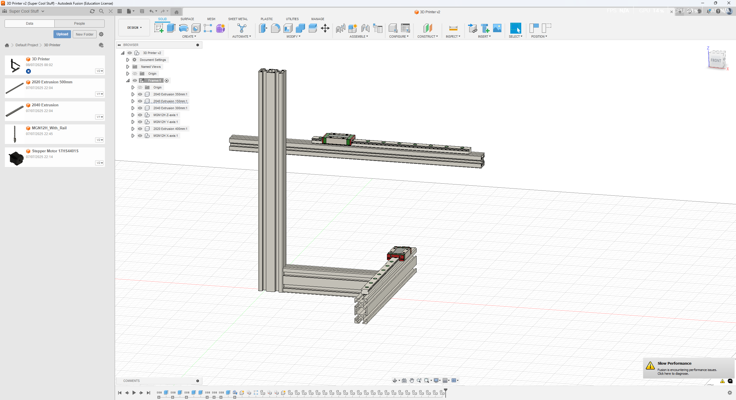
I started off by searching for some 2020 and 2040 extrusion. Eyeballed the lengths to be 350mm for the Z, 150mm and 300mm for the bed, 400mm for the X-axis.
The extrusions will be joint together with joining plates. Maybe I will add some other joints, tbd.
Then I added the linear rails. The grabcad model was only 100mm long, so I had to extend it to 250mm.
I do not know why, but Autodesk Fusion was playing tricks on me the entire time.
For the life of me, I couldn't understand why Fusion was chopping off parts of the entirely different bodies from different compontents. When I tried splitting the 100mm rail to 50mm, it would split every single rail part and then when I went to delete the extra 50mm, the rail would suddenly have holes in them.
It happend in other areas too, like the extrusions. When I went to extend or cut an extrusion, the other extrusions would cut themself too. I ended up somehow forcing myself through the problem, so if anyone has some ideas, let me know.
Time spent on that day: 5h
2nd entry: July 8th, 2025
Did some searching and came to the conclusion, that 2040 extrusion is too flimsy and decided to swap out the extrusions for 3060. I also searched where I can buy the extrusions and found a Polish shop that sells custom lenghts for a really reasonable price.
3060 for €0.30/cm and 2020 for €0.12/cm.
The bed has been a quite the headache. I can't really make my own bed as I do not have the equipment necessary, so I need to buy one pre-drilled and tapped.
I did find a Ratrig V-minion heatbed assembly, but noone has bought it so it is kinda risky. The other option I found was the Micron180 heatbed assembly.
It has all the necessary things included for €60, but I might need to swap it out later when I optimize the BOM.
The Micron has a slight flaw for my use case, it is designed to be mounted fixed to the bottom of the printer. Which means, the mounting bracket that goes between the bed and the linear rail carriage has to be huge.
I started the day off with replacing the extrusions and fighting with Fusion a bit. I have managed to make sense of the problem a bit, but still kinda wonky.
The rails were next. They were less of an issue, but with the Fusion magic again, I am having a hard time categorizing the models into components. Please do not inspect the components too close.
The mounting brackets were next. I did several designs and L-shaped mounting brackets that I found on that Polish website seems to be the best. I did add a T-shaped bracket to the bottom and normal corner brackets for reinforcment.
I found the CAD model for the Micron180 and just took the bed assembly out of the file. ;)
I did have to modify it, removing the extrusions, making a carrier plate for it, etc.
The carrier plate might actually not warp, I need to learn how the Fusion simulation works. I have a feeling it will not hold up.
Time spent on that day: 7h
3rd entry: July 9th, 2025
I started the day researching again.
Looking over the BOM and the design, I think I can build an CoreXY for not a lot more and a lot faster and probably safer design wise.
The bed on the cantilever design is really suspicious.
I decided that I will make a flying bed and not a flying gantry.
The Z will use 4 linear rods and 2 Z-motors with screws. This is because I only have 2 Z-motor drivers on the board and beacuse it is cheaper.
The Z will use 10mm linear rods, LM10UU and Nema17 motors with lead screws on them.
Hoping to find motors that aren't that expensive.
Found basically Prusa MK3 Z motors with built in 300mm lead screws, will use those. They come on the printer in a 2 pack too, which is kinda amazing. The stars are slightly aligning.
There is a posibility of using some more Prusa motors. That makes the project a bit more accessable (if someone has MK3 motors lying around).
It is possible to use the MK3 bed and Y-carriage as well, but I don't have them and they are more expensive than the Micron180 bed I want to use.
The beds should be replaceable with a few design tweaks.
I also made the BOM a bit more complete and I am going to have to source a few parts myself beacuse the BOM is offically blown out of budget.
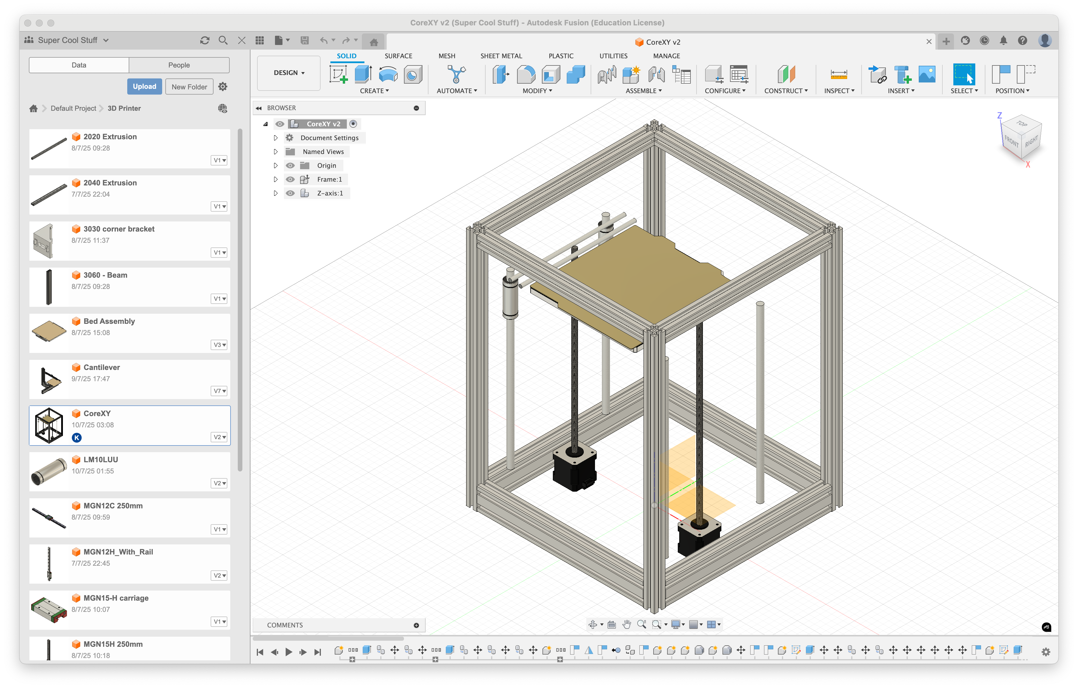
I started doing the CAD for the CoreXY printer.
I decided to use 2020 extrusion as there is more of it, so the rigidity shouldn't be a problem, and it is quite a lot cheaper.
The bottom of the printer is under review. I might make a skirt for the electronics or I house the electronics at the back of the printer.
I got the linear rods placed, the bed placed, the NEMA17 motor and its accompanying lead screw and the lead nut placed. The second linear rods used to connect the lead screw and the Z-axis linear rods were also placed.
Next up I need to make the connecting piece that will be 3D printed.
I have realised that I really do like tinkering in Fusion and researching the parts. It is quite hard, but I like the challenge.
Aimlessly modeling is very time consuming, but when I achive the aim, it gets quite rapid.
Time spent that day: 8h
4th entry: July 10th, 2025
Still thinking about the design of the printer.
The SKR Pico 1.0 that I would like to use beacuse it is so cheap and there is a possibility of using a CAN transiver so you do not have to buy a seperate CAN board.
The SKR Pico has 5 motor drivers - Extruder, X, Y, Z and Z2.
When researching Z axis beds on other printers, I realised that having 3 Z-motors would be advantageous beacuse the bed could trim itself. There would be no need to trim it yourself, just use the ZTILTADJUST in Klipper, just like the Voron Trident.
Then I thought to myself, would I need to swap out the SKR Pico for a board that has drivers for the Z.
But then I realised, if I use a CAN toolhead board, it has a built in TMC2209 for the extruder - I don't need the extruder driver on the board anymore, so I can use that for the 3rd Z motor. I did some searching (asking AI) and it is indeed feasable.
I then decided to change out the Z axis design again for the Voron Trident design.
I went to the Trident configurator and for a build size of 180mm3 it recommended me the frame size of 340x340x430mm - basically the frame size I was already using.
I searched a lot on aliexpress too. I think I had over 100 tabs open at the same time (thank you Zen browser for saving me a bit).
I went down a different rabbit hole of what if I pivot again and build a cartesian?
but that I shut down as there isn't really any reason to pivot again.
I searched about all the different motors out there. There are a lot of them.
But they have quite awful shipping times. If I buy them now, it will take almost a month to get to me. This is also the reason why I am crunching so hard. Time is of the essense.
I watched a cool video about how to build a 3D printer, it is a bit old at this point (5 years at the time of writing), but still quite a good watch. How to Build a 3D Printer (The Ultimate Guide)
I was really worried about the shipping costs on the motors. They ballooned way out of porpotion. I was really doubting if there are any cheap motors out there, but then I found Robotdigg.
It is quite a cool site and they had the motors with lead screws that I needed, the shipping was around 30 euros.
I wasn't satisfied yet. Over 120 euros just for Z-axis motors is just too much on a somewhat budget printer.
I had my eye out for the motors on the BOM, but there was a small issue - I could only buy one. That made me search for better option, but there weren't any and then I circled back to these.
I do not know what kind of trickery AliExpress does some times, but when I opened the tab in incognito, I finally was able to buy more than one.
The price is around 4 euros more, but I would have liked an option to discard that promotion so I could buy more of them.
There should have been a pop up that said Hey, I see you are trying to buy more than 1, would you like to get rid of that exclusive offer?
But I digress, I finally got some cheaper motors for the Z-axis but the tomfoolery wasn't done just yet.
The A/B motors were also quite the challenge. I searched far and wide for the motors that ended up in my BOM, none were quite good enough. Not enough torque, too hi inductance, not enough current, etc.
There was the shipping problem here as well. As soon as you ordered more than one, the shippiing shot up to around 30 euros. This was double the price of the motors together, so I had to find some other ways.
The way ended up pretty simple. Find some that come in a pack. This eliminates the shipping cost on pretty much in all cases.
I found the 17HE19-2004S motors. They are powerful, have a pretty low inductance and are cheap. They only come in a pack of 3, not 2 that are needed - so I guess one is extra just in case.
I started the CAD redesign by removing everything. This day has been heavy on the modelling side.
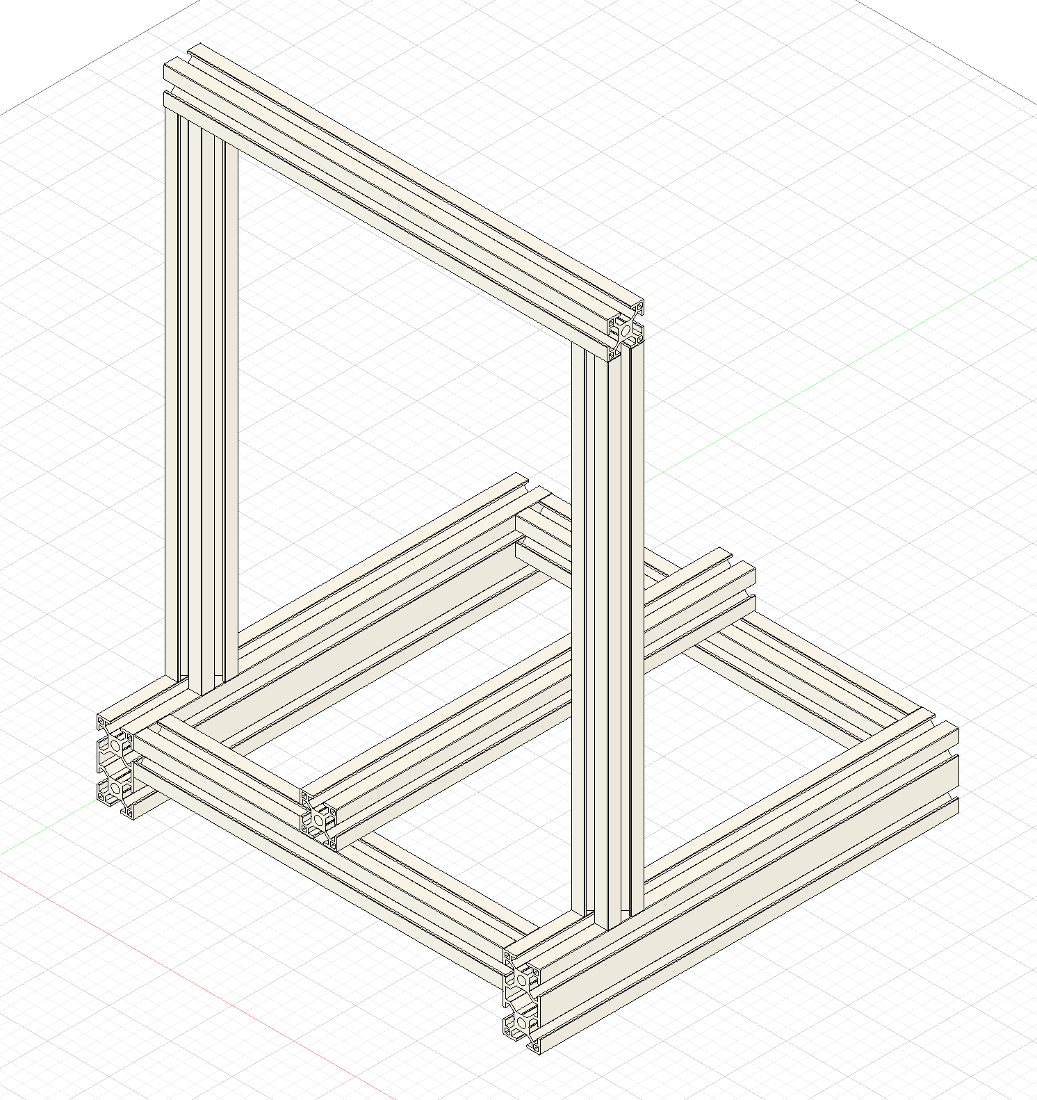
I remade the entire frame. Slightly modified the dimensions.
I added the backbrace to the frame for the 3rd Z motor.
I added the linear rails, the stepper motors with the lead screws.
I added the bed, the aluminum braces under it.
I did take the bed holder mechanism from the Voron Trident, very many thanks to the team and the contributers that make that project happen.
As my bed is quite a lot smaller than the Voron Trident's bed, I had to modify half the mechanism to work with my smaller bed as there is enough room for the big and bulky mechanism.
Should have I made the frame bigger? I guess we have to find out.
The margins on the parts are still quite small, maybe even hitting the aluminum bed, I will have to find out when I build the machine and modify it a bit.
Added 3-way corner connectors to the build.
Started designing the gantry.
Total time spent that day: 8h
5th entry: July 11th, 2025
Oh how many different options. I started questioning the corner connectors. Are they even good for a 3D printer? Are these the better option?
I didn't want to use blind joints as they require drilling new holes into the extrusion that I am personally not confortable doing. I could figure it out but I don't want to risk it.
Then I saw the openbuilds corner cubes. They seem good and sturdy. Tapping the ends of the extrusions doesn't seem all that difficult. I was ready to add them to the design when I found out how expensive they are.
I mean they aren't that expensive, but still are quite a bit more expensive than just using corner brackets.
I have to use corner brackets anyway for the bed frame so might as well use them all throughout.
20pcs with hardware is 12 euros as supposed to corner cubes with are 14 euros for 8pcs.
I started by replacing all the frame extrusions again. I saw that there are differences from extrusion manufacturer to another in a YouTube video about blind joints.
I found the technical drawings of the manufacturer on the Polish webstore where I found the extrusions and I started to create a sketch, made almost halfway to a finished sketch and then I found they just have a 3D model available...
I downloaded it and replaced all extrusions on the design with the new one. They are indeed different but not by much and I really doubt it was neccessary.
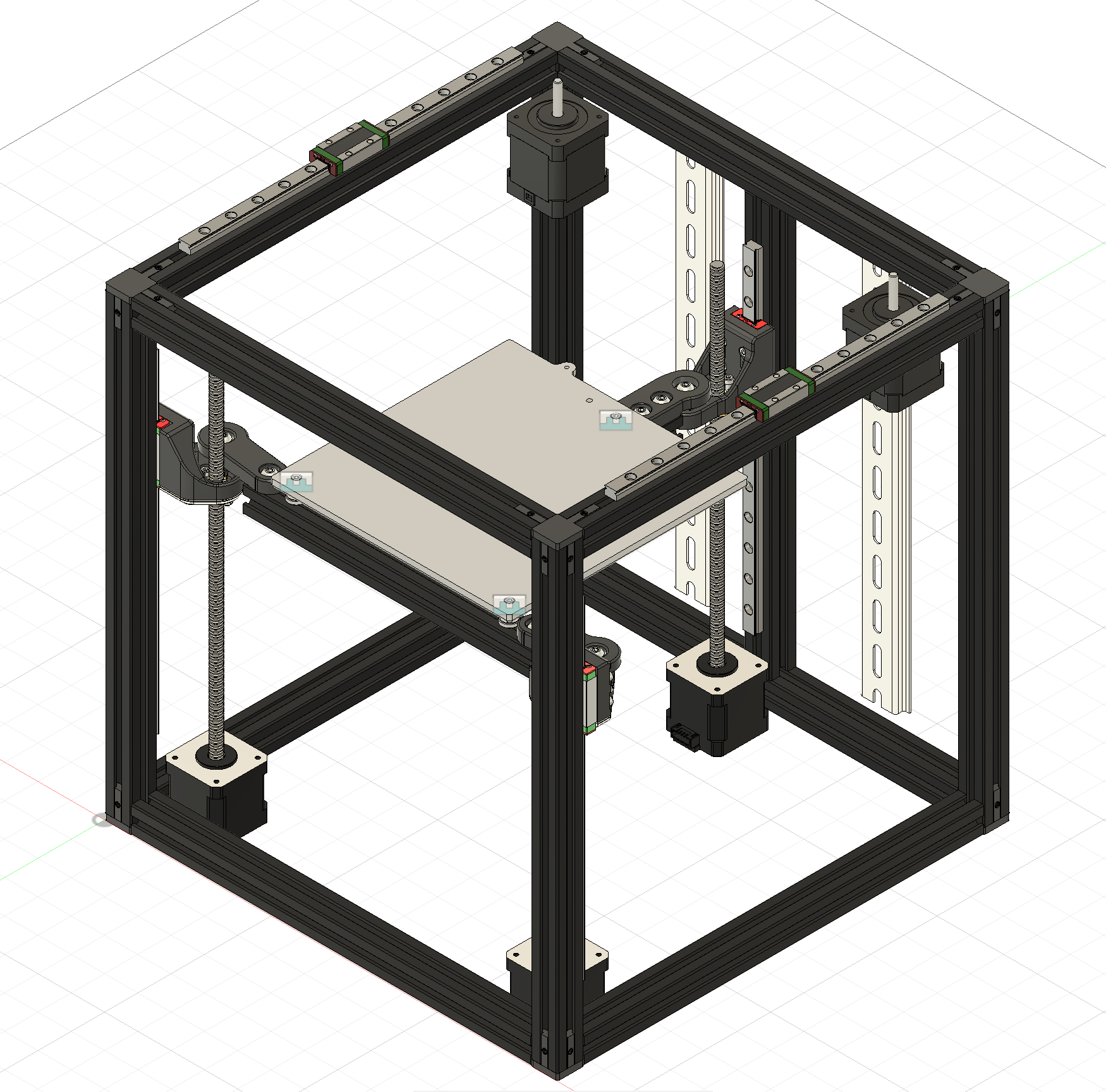
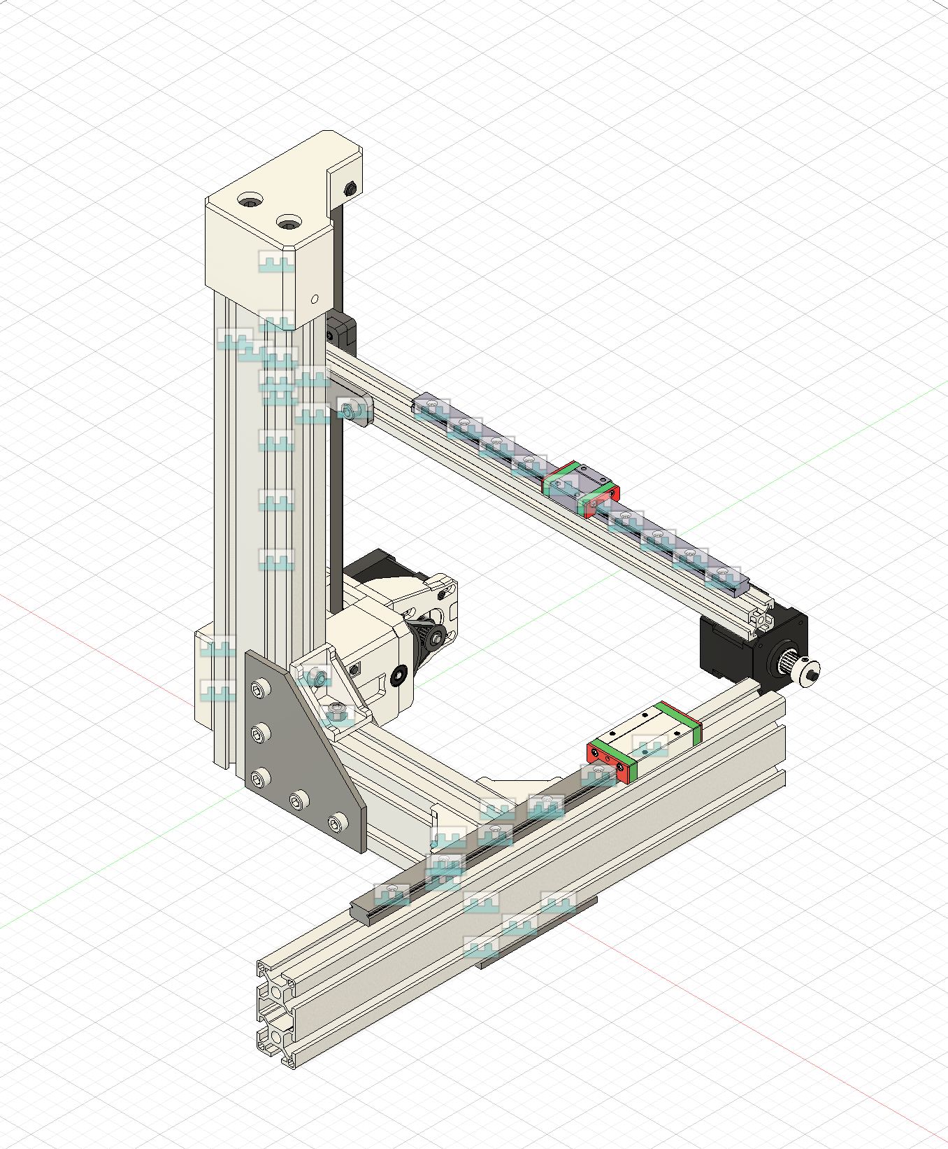
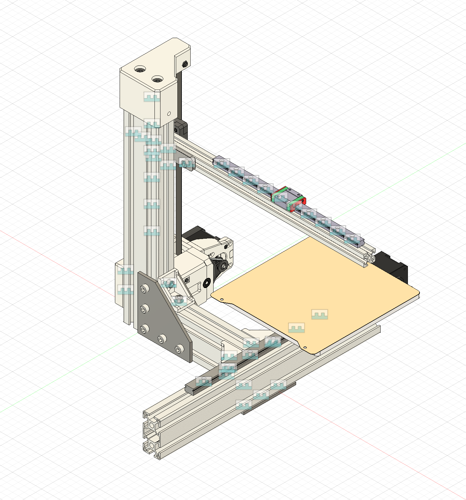
Started making the gantry.
Total time spent that day: 5h
6th entry: July 12th, 2025
Today started off different. No researching, just modelling.
Made the X-gantry belt/extrusion holder. It was actually not that bad. I found models for heatset inserts, F695 bearings.
The real complexity came when I finished the gantry and noticed that I do not have enough room in front of the bed for the toolhead.
As I want to use the eddy probe and use the tapping functionality in the eddy-ng project, the toolhead needs to fit over the bed.
This would not have been possible with the current design, so I needed to make the frame bigger.
This meant a lot of backtracking and modifying the existing design.
Uhmm, this is kinda weird. After coming back to this, I got recommended a ModBot YouTube video exactly about eddy-ng. Perhaps he saw the project the same way I did, Voron discord server.
The A/B motors mounts were next. They were pretty complex, I am doubting my abilities to create a working model, but when I get my hands on the parts and assemble it, I can tweak the models.
I had to figure out how to make the belt tensioner. I first thought of a way where the motors move, but then I thought of a system where the front pulleys get pulled closer to the front.
When I had done those, I went and made the electronics bay. I found a model of MeanWell PSU I am planning to use, but as the electronics bay uses DIN rails, the mounts are easily interchangeable.
The diary entries get shorter and shorter as I have less and less time, but I still have managed to crunch my way through. I just need to make the toolhead, finish the electronics and the BOM.
I want to add a nozzle scruber to the bed assembly too, but that stage comes a bit later.
That is about it for today. I kinda need to fix my sleep schedule, all these late night CAD sessions aren't probably good for me.
Total time spent that day: 8h
7th entry: July 13th, 2025
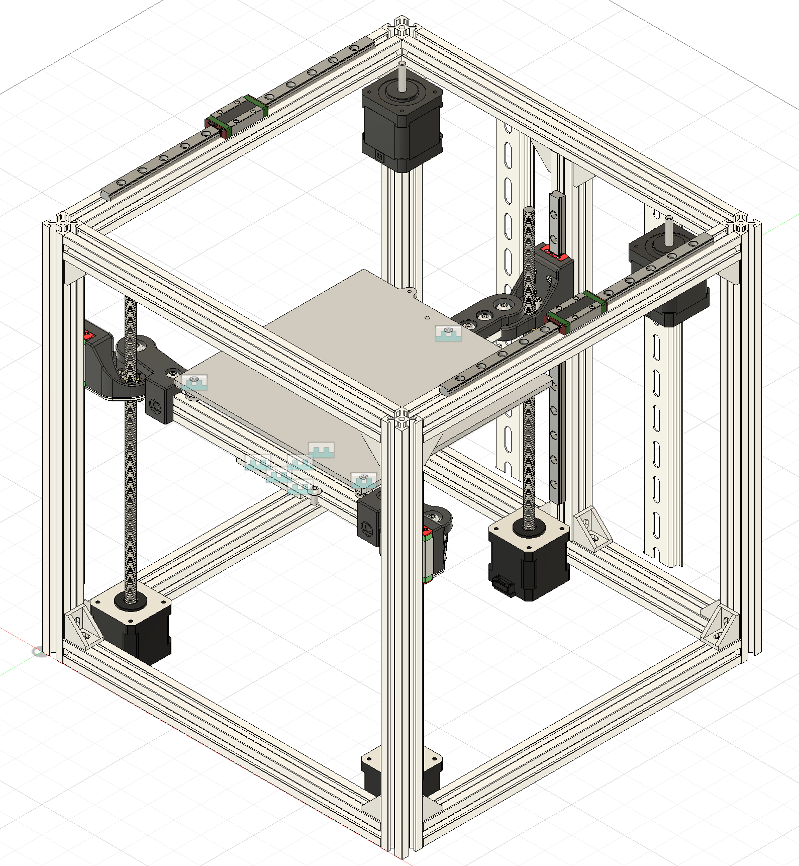
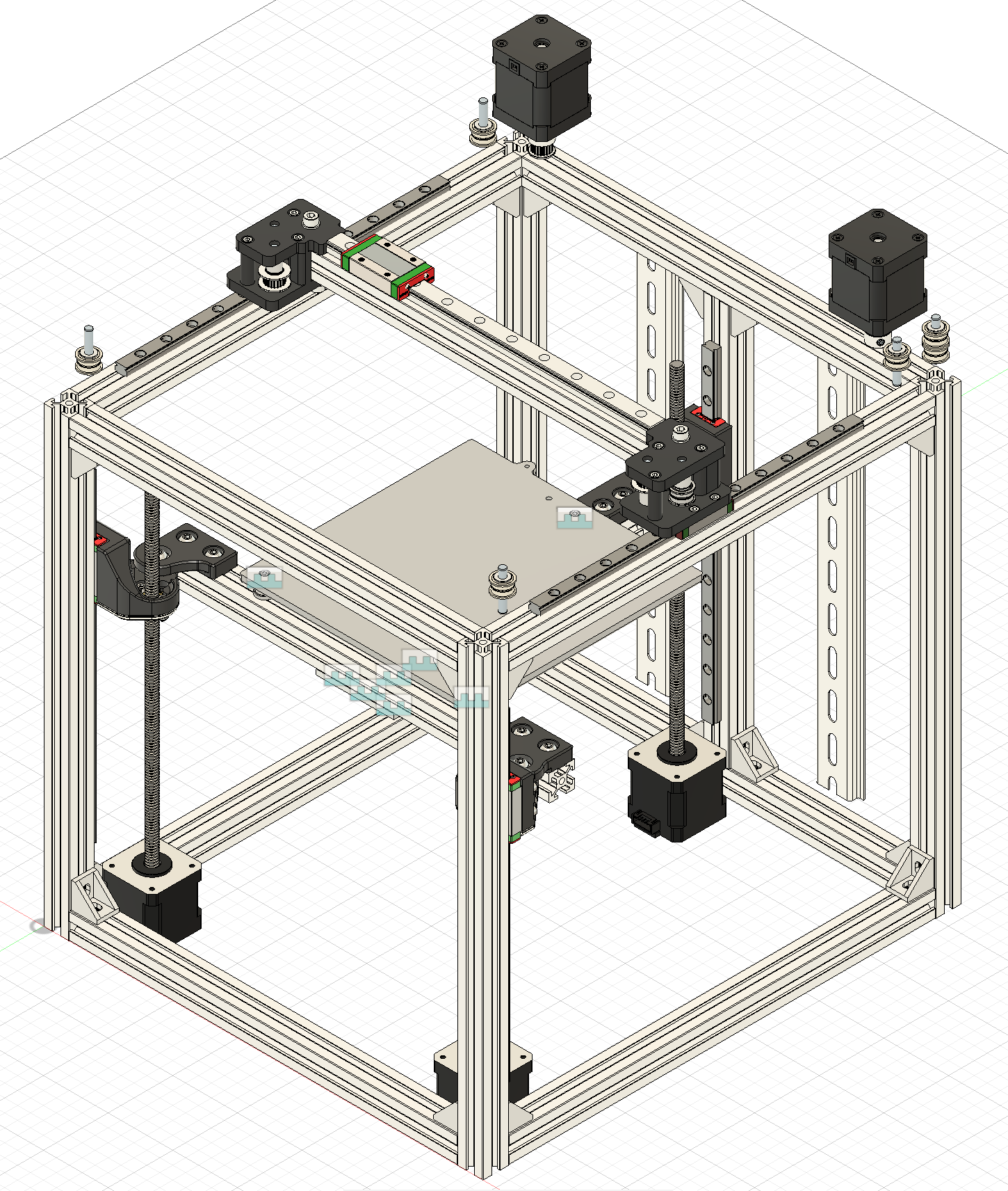
Finished the CoreXY printer, but when looking over the BOM it is really expensive. I might choose to change it out to cartesian platform or even go back to cantilever.
Spent a lot of time researching on how to make the CoreXY cheaper, but to no avail. Still seems too expensive.
After that I made the decision to move to a cartesian platform.
I made the frame out of 3030 extrusion for the cartesian printer, but the problem is joining the extrusions together, the frame needs blind joints, but I do not know if I can do it. Would love it if I didn't have to do blind joints.
Need to reaserch a bit more.
Total time spent that day: 2h
8th entry: July 14th, 2025
Started with research. How do save costs on a 3D printer while still maintaining speed?
Saw that the RatRig V-minion is a good printer with good speed, but it is not available anymore and is a bit too expensive.
Decided to make a cantilever design inspiried by the V-minion. I do not like that it has a lead screw Z and would like to make the electronics mount on the printer and not be on a seperate box.
Total time spent that day: 2h
9th entry: July 15th, 2025
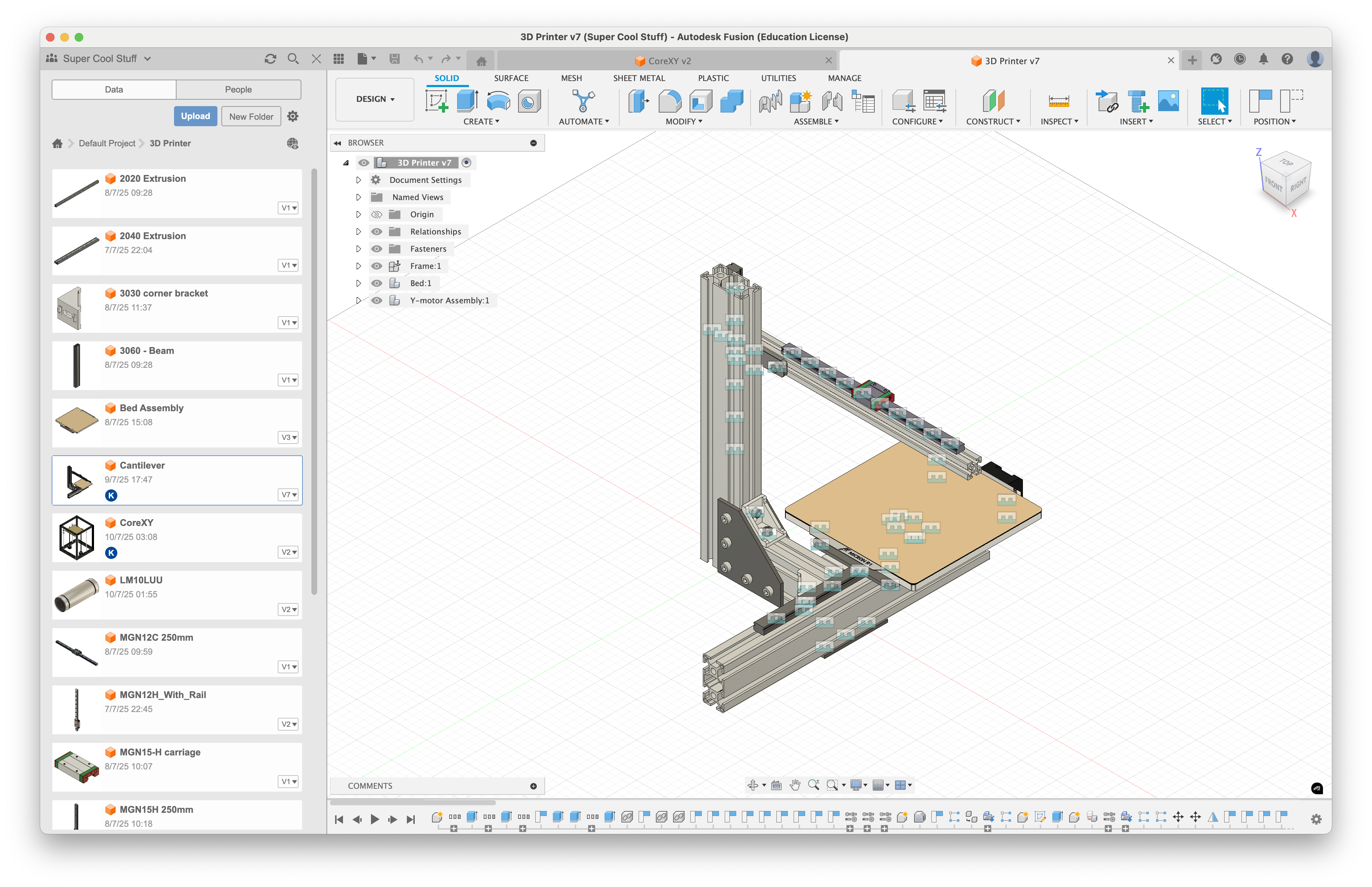
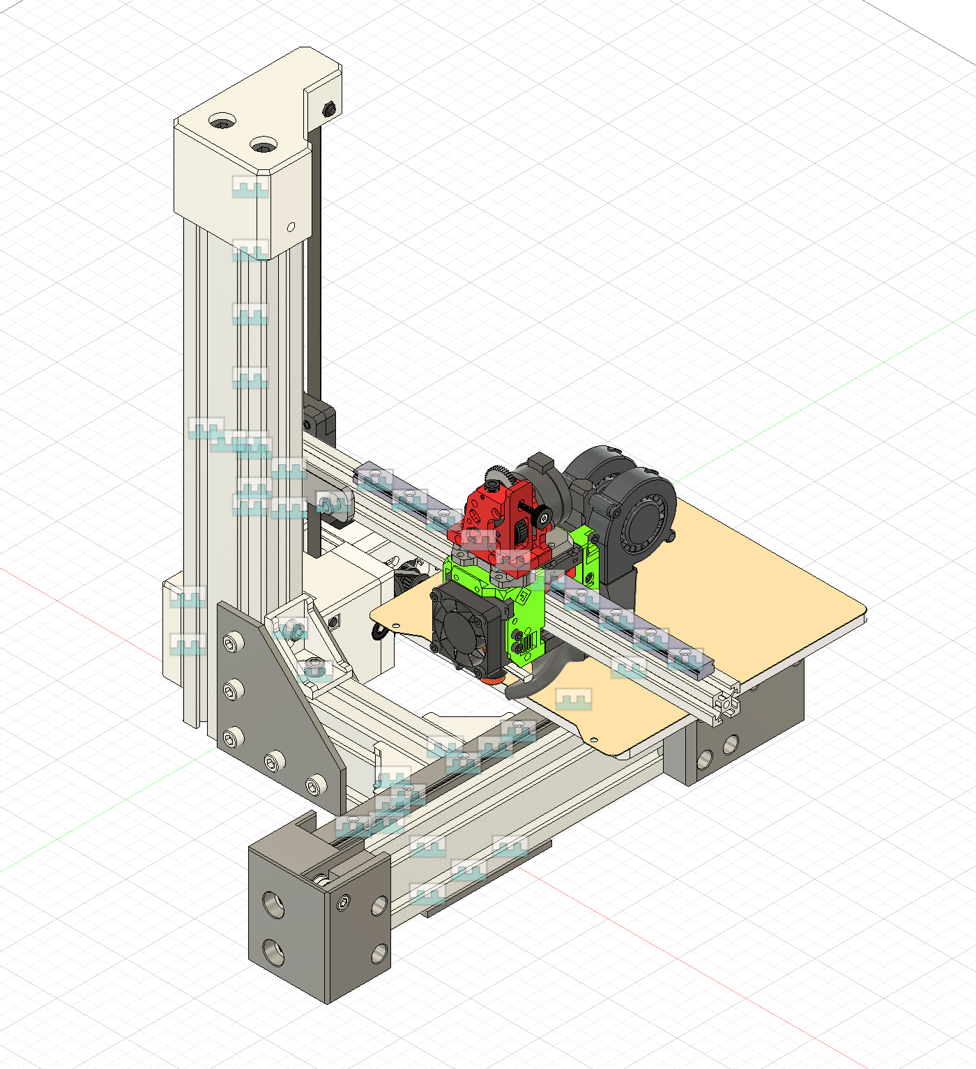
Made some improvements to the printer. The Z axis is belted, the bed is still 180x180mm big, but the footprint is smaller.
Started making the z axis and bed.
Saw from the Micron180 that the Z-axis should have a gearbox of some sorts to stop the X-axis dropping down.
Decided to make the gearbox similar to the one on the Micron. I will adapt that onto the cantilever printer.
The bed was quite simple. I found a 180x180mm bed for cheap. The Lerdge iX print bed. Its heatbed is only about 25 euros and has the mounting holes close together, so the plate under it doesn't need to be that big.
The problem with the bed is that it is quite thin and doesn't have the power of a silicone heater, but I think that it will be good enough.
The plate should be made from aluminium, but that is quite expesive, so I think I will try and make it using carbon fiber infused filament.
Search for suitable filaments and found the PLA-CF from Bambu Lab. It doesn't have the bending modulus of something like Nylon, but it is pretty close.
Bending modulus is the bending force the filament can withstand - or so I think.
I just need to add some silicone spacers so the hot bed doesn't touch the plate. Might still need to make the plate out of aluminium if this doesn't work.
I uploaded the plate design to JLCCNC and the quote was around 20 euros plus shipping. Not too bad, but that still would eat into my budget more than I would like it to.
I found the JLCMC website, even though I have ordered from JLCPCB in the past, never have my eyes wondered so far that I find this website. Looks cheaper than AliExpress but I will have to search this site longer at a later date.
I can get a whole Voron 2.4 350mm spec frame for 20 EUROS! My jaw dropped when I saw that. Literally a similar frame on AliExpress is 77 euro. Holy moly. What a find.
The best part is the global direct line shipping took me like under a week the last time I ordered from JLCPCB. I have to find out more about this website.
Total time spent that day: 2h
10th entry: July 16th, 2025
Today we got back to grinding.
Made/finished the Z-axis design. The Z-axis uses a 20T-80T gearbox, so the gear ratio is 4:1. This should be enough to hold the printer up. If not, I could switch the 20T out for a 16T for a 5:1 gear ratio.
Made the Y-axis parts, like the motor mount, idler mount and plate mount. The plate is quite sketchy, but if something ends up being wrong after I send it to JLCCNC then I'd be screwed. So I will try the printed plate and if that fails, I will get a aluminium plate.
Added a few things to the BOM, like the bearings and other knick-knacks.
Almost finished design. I just need to make the X-axis and toolhead. I wanted to just use the EVA3 toolhead system, but we aren't allowed to just copy parts, so I will make my own.
The printer is almost ready. I need to finish it fast as the shipping times get longer and longer.
Oh, and also need to make the electronics bay.
It really is a race against the clock.
Total time spent that day: 6h
11th entry, July 17th, 2025
The day has been mostly designing, but also reasearching different hotend options. I had already picked out the TZ V6 hotend, but I wanted to see what other options there are. There aren't a lot of hotends that specify how much plastic they can push through, so that makes it a lot harder.
The EVA toolhead is a refrence, it will be replaced by my design.
I did end up just sticking with the TZ V6.
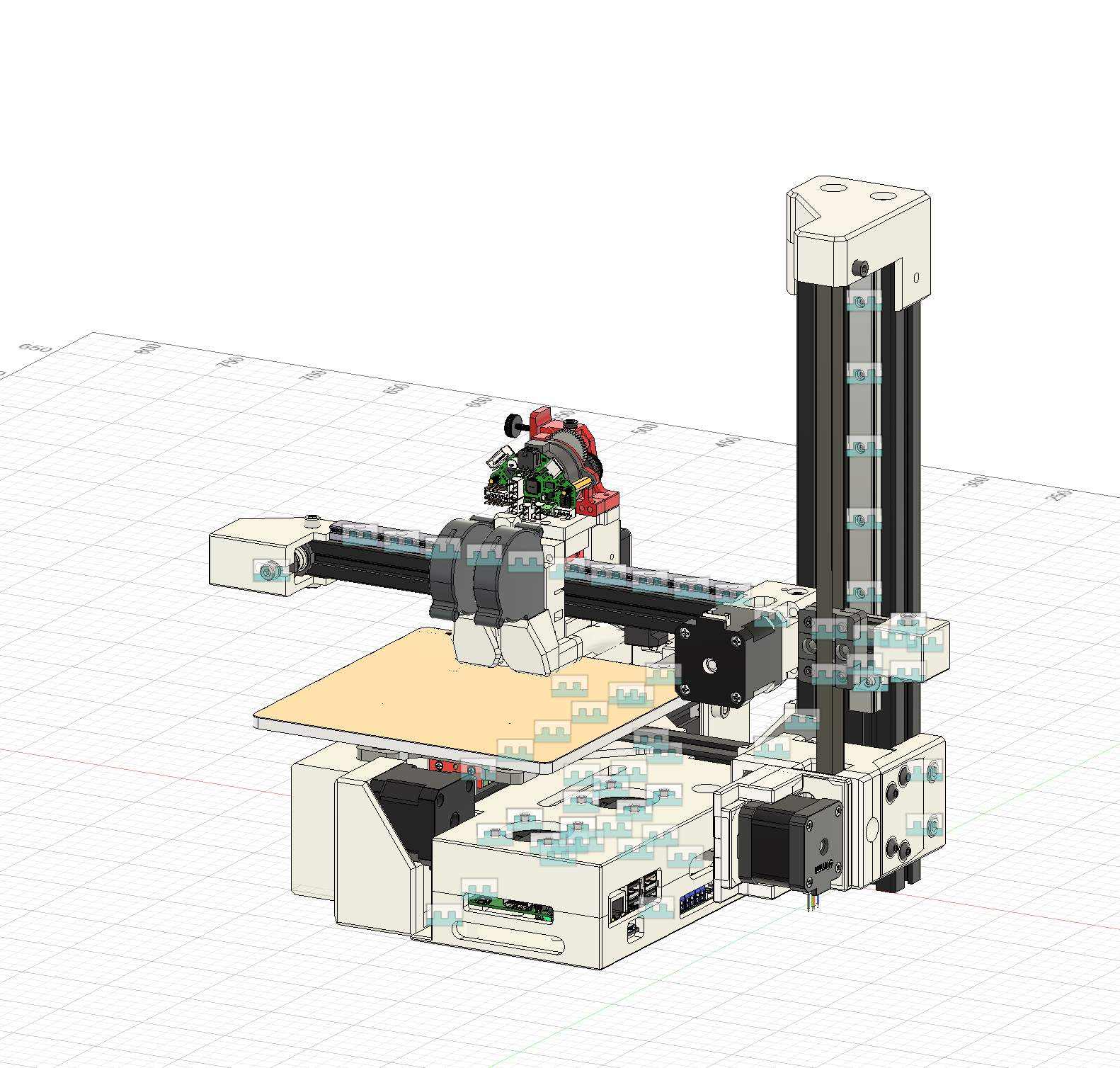
I designed a toolhead too. The main inspiration is the EVA toolhead, as I like the modularity it offers if I decide to swap things out.
The hotend is cooled with a 4010 axial fan to minimize heat creep and the part cooling is using two 5015 blower fans.
It probably is a bit overkill, but I want to make the printer go brrr fast and I need to cool the part fast for that.
Total time spent that day: 8h
12th entry: July 27th, 2025
I have been really really busy and haven't had much time to finish the design, which is sad as I do not have enough time to build it before the 7th of August.
I need to check over my PC as Fusion is really really slow and it is really hard to design.
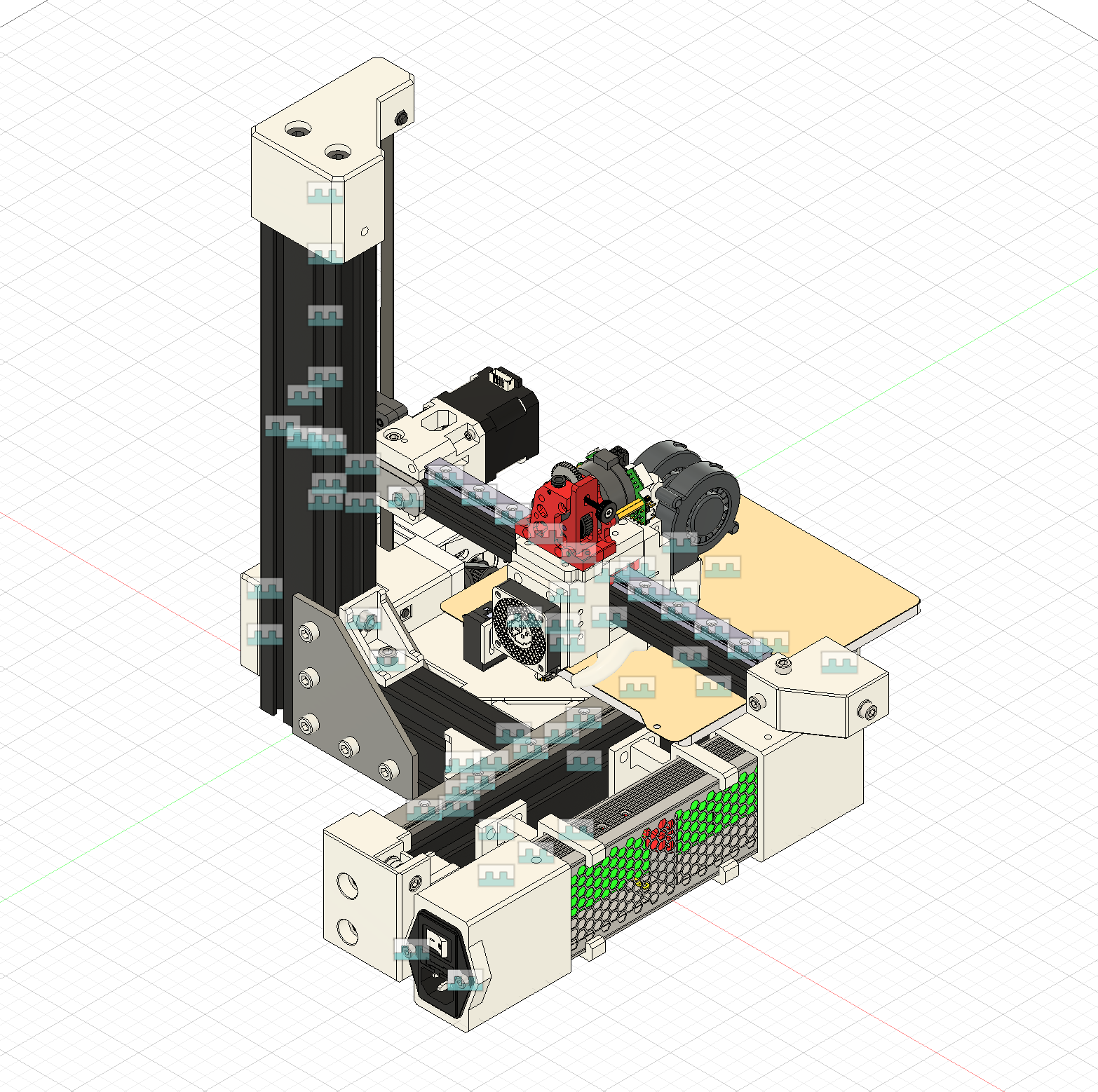
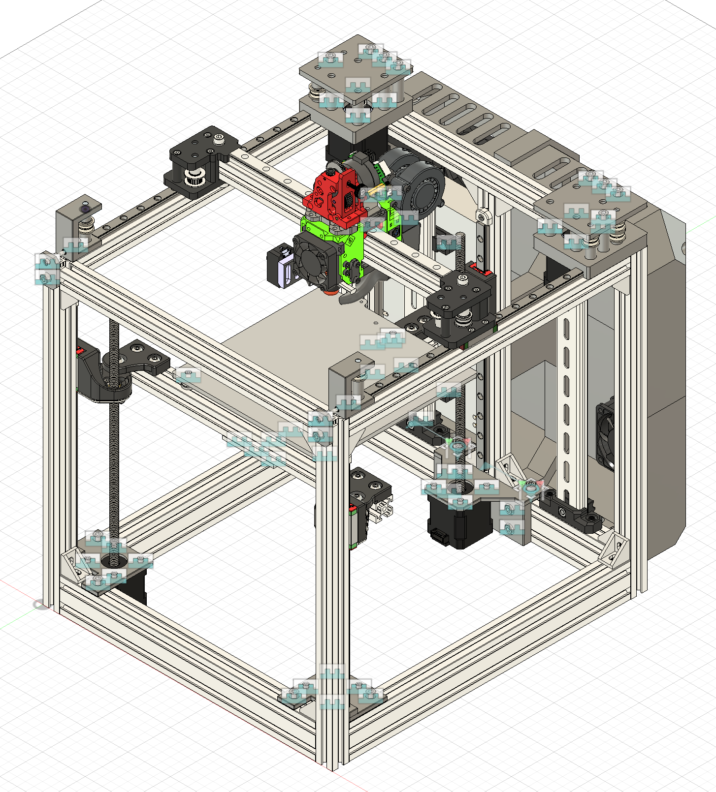
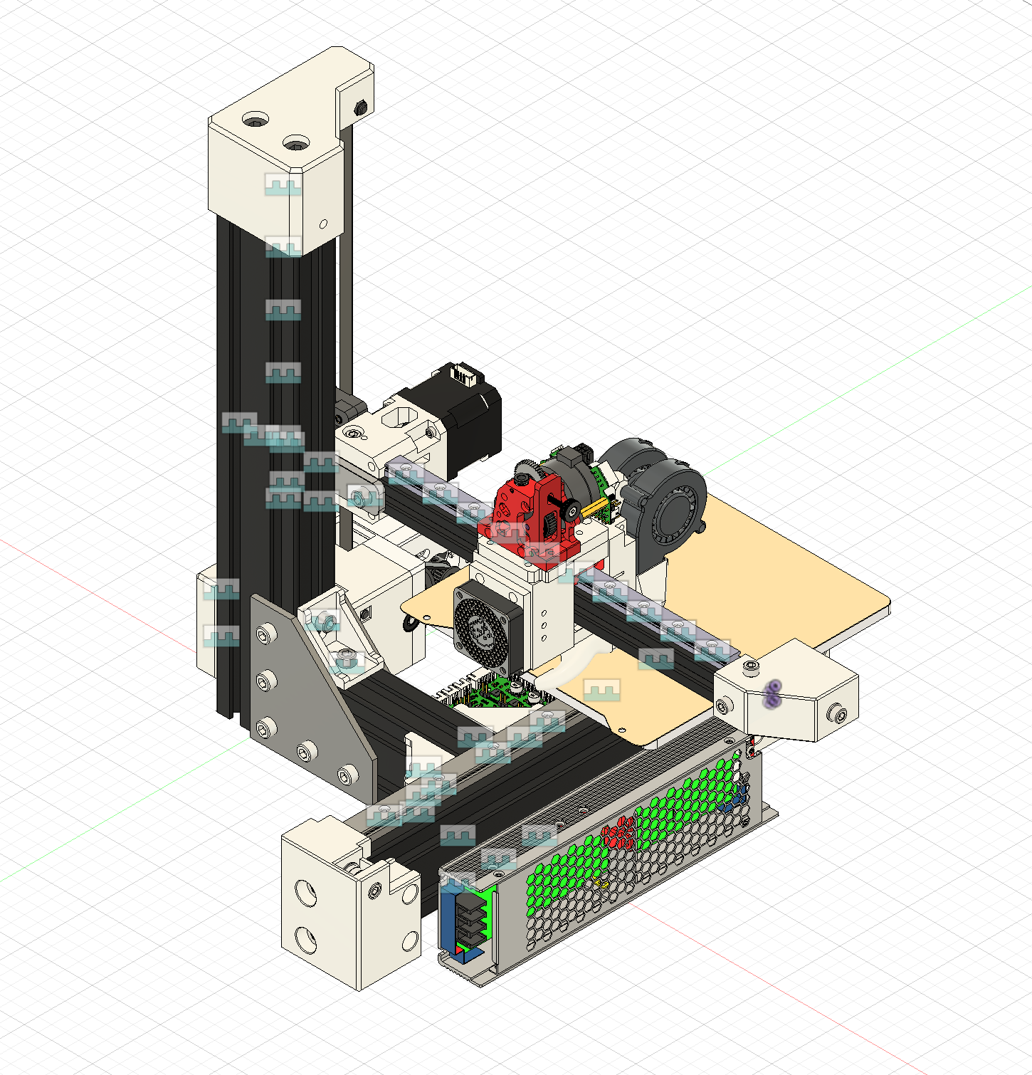
The printer is done. I have finally finished it.
Today I did the electronics box, the PSU mount, finished the toolhead, all the other bits and pieces.
The electronics box was harder than I expected as I do not have anything to base the design off of in the real world. Is 50mm of clearence enough or do I need more? Can I make I smaller, etc.
It has been quite the journey and I have learnt a lot. This is the first printer I have designed and it shows. I have taken inspiration from already made printers in the hope of not burning anything down and making sure everything works.
The only challenge now is to make it in real life and to tweak and tinker with the design even more to finalize the design.
I need to look over the BOM and sumbit it.
Total time spent that day: 6h