
Ulti-Board
The ultimate keyboard for all your daily needs.
Hi this is my journal on making the Ultimate Keyboard. How did this all start? Well thats whats coming up.
Total Time Worked: 57 Hours and 45 mins
I had no Idea it took me so long to make this
Its mostly cause I had to redo my pcb from scratch several times
but still, that pretty sad :(
May 31
Time Worked 5 Hours
This morning I woke up and knew that I would have to lock in and work hard because I hadn't really done anything for the past week except research some key things about making a keyboard and waiting for my gamepad to be accepted (I would appreaciate it if you could check if thats possible(That is if you can)). So today I decided that instead of resarching more about keys and leds to use I would just use the ones that were In the gamepad.
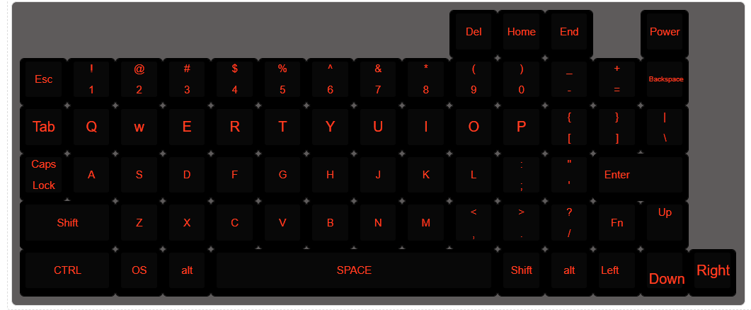
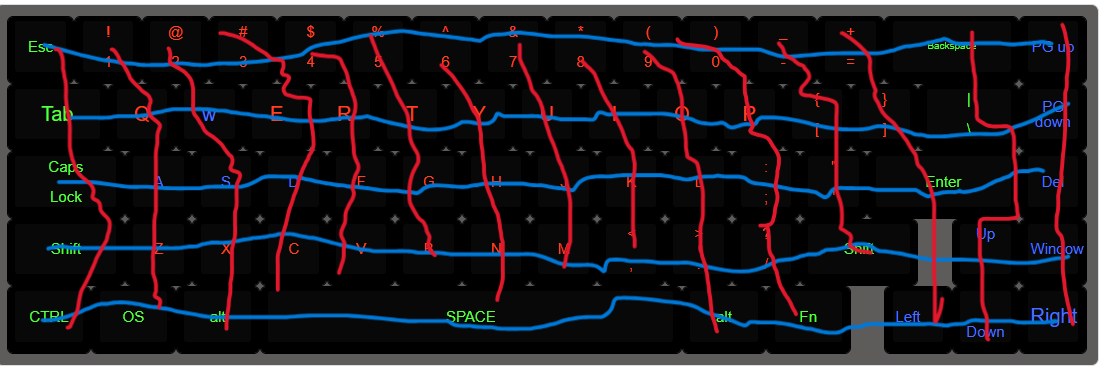
I started by making the schematic, I knew that I wanted the layout to look something like my current keyboard but I did want to customize it a little bit.

To
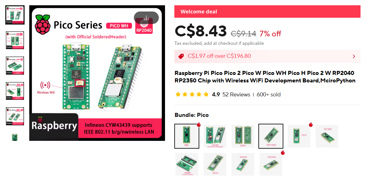
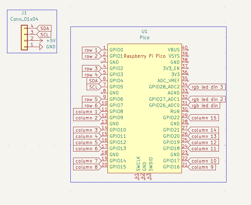
Next to make the schematic I knew that I would need a lot of GPIO pins so I decided to use the Raspberry Pi Pico
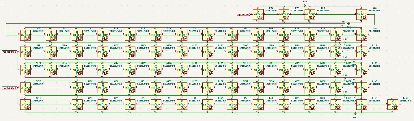
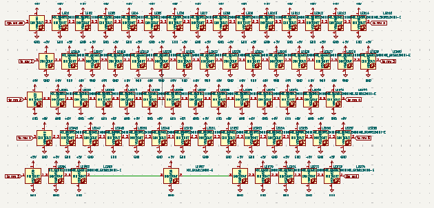
 since i already had the symbol for the sw_push and sk6812mini e led(i think thats what its called) I decided to make the grid for the switches and the leds.
After I did this I wired all of them up. I wired the keys in an Matrix format and the leds in rows. I originally wanted each led to have a different color but quickly decided that that was kind of advanced and I would probably need a lot of GPIO pins. So then I decided to keep it so that each row would have its own din from the pi pico.
Next I looked up and found the pi pico board symbol and footprint. I downloaded these and imported them to kicad and added it to the schmatic.
When it came to wiring the pico with the keys and leds I decided to use tags so that the schematic was more readable to anyone who wanted to read it.
Next I wanted to add a oled to the keyboard I needed a symbol and footprint for this but I was unable to fine one. I looked around and tried different things for a while(it was a long while) and came up empty. But shout out to This post because it solved my problem and I am sure it also solved others problem as well.
But I ran into a huge problem I RAN OUT OF GPIO PINS ;(. So i decided that instead of every row getting its own color i would give every 2 rows its own color.


See You Tomorrow
June 1
I really didn't do to much over the weekend exepct check up to see if my first subbmision got accepted or not, and it wasn't :(
June 2 - 4
Time Worked 10 Hours
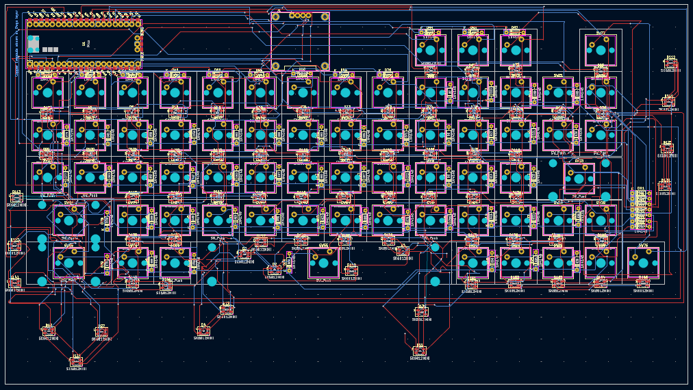
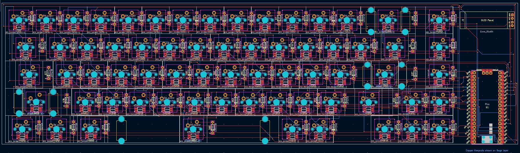
This is when i started to do the designing for the pcb. The first thing i did was make sure all of the right footprints were assigned and then imported it all into the pcb. I decided the it was a good idea to put all of the keys in first into a grid and then add the diodes and the leds after. I put the leds in a grid where the white lines on the outside lined up and started putting the diodes and leds in the right area as well. This is where I ran into a big problem that I didn't really realize at the time. I did not have enough space to put everything but I would realize that later. So I decided that each diode would go to the right and each led would go beneath its respective switch.
Once I was done putting it all in the right spot I started to do the wiring. I just followed the blue lines to an extent and add vias when another wire got in the way. I thought that I had done a great job at the time and wanted to see how it would look in 3d view. I was disappointed when I open the 3d view and just saw the pcb and diodes without the leds or switches and was determined to add them in.
I opened the fooprint editor to find that the path at which it looked for the footprint was wrong in each key and led. I also realized that I had much to mant footprints to go in and change each one individually so I came up with another plan. I decided that I would open the file in VScode(which is where i am writing this rn) and make changes to the model prams. this would make it much easier because of the fact that I can use the shortcut CTRL + F to find and change all of them at the same time. I still took quite the entire day to get the model in the right spot but this is when I came to an very important realization. The model for the switch and the leds were slightly overlapping. I didn't want to take any chances with this and decided that I would take a break to find out some other choices that I have.
Thats all for these three days see you next time.
June 6
Time Spent: 5 Hours
hii so i decided that I am gonna start everthing again from scratch. Yup I am just gonna delete everything. Why? well I found a very usefull library of footprints and symbols on Github, and I feel like the quality of my keyboard will be much better if I am to use that instead. I feel like this library will be so useful so thanks so much to ebastler for posting this
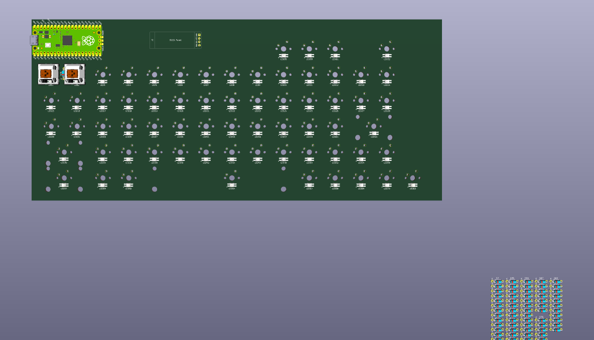
So I replaced the symbol for the key with the new one and changed the leds as well. This didn't take to long prob like an hour but I feel like it was a very big foot in the right step. Next up I had to line it up in the pcb this took a little longer because I knew that if anythin happened to be in the wrong spot after I started wiring I would casue major problems so I took it slow. I first put all the keys into the right place as well as pico and the oled display next it was time for the leds.
This probably took the longest time becasue I knew that if the led did not fit in the cavity given in the rbg variant of the cherry mx I would use then it would be a big disaster. This is why I tried to line up the outer line to the best of my ability as well as prob the main reason it took so long. Why? because my grid setting was on the custom one made on the hackpad guide website and for some reason the box would always be slightly of so I used a smaller grid and moved all of them to the right place slowly but surely.
After this it was time for the diodes I placed a couple and then I tried to get all of the footprints to show so that I can tell if there is some sort of overlap or something like that. It didn't look like there were any 3d models in this library so I decided to use the same ones that I was using earlier. I know had to go into each key's footprint and change the path of the 3d model to accomadate this. At this realization I decided to finish up for today and do some more work tomorrow.
Done!

Done!

Done!
Done!

I am not done puttting these pieace in the right spots

Still adding more 3d models
Thats all for today see you tomorrow
June 7
Time Spent: 8 hours
helllo so today I will put everything in the right spot wire it up and also get the 3d models in the right spot as well.
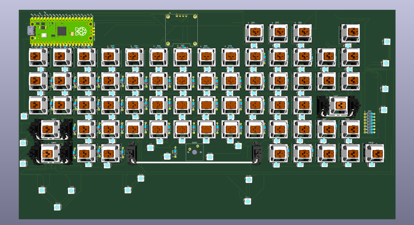
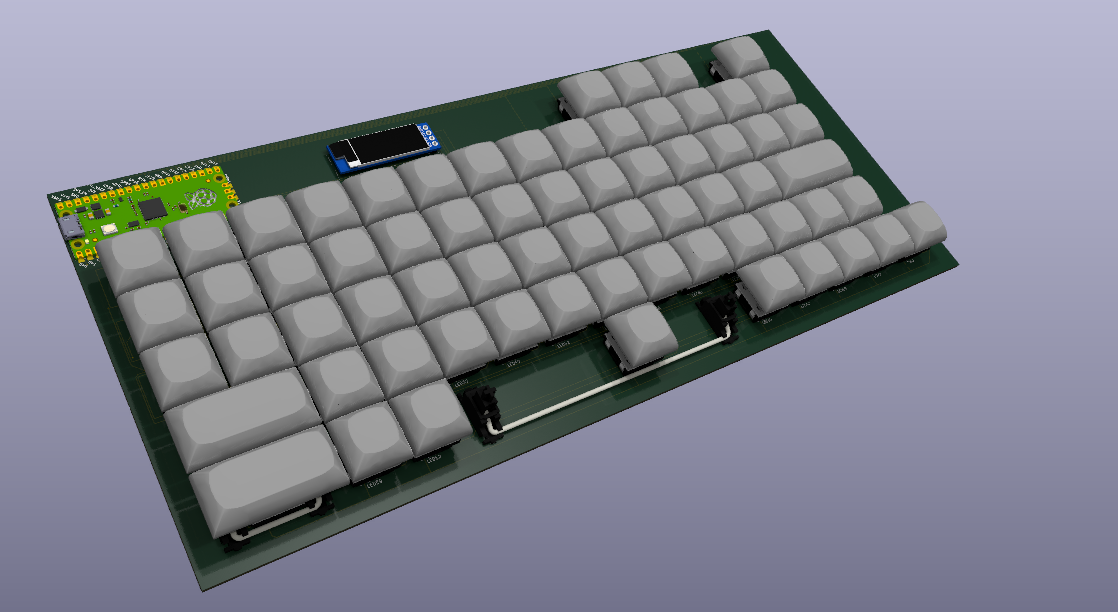
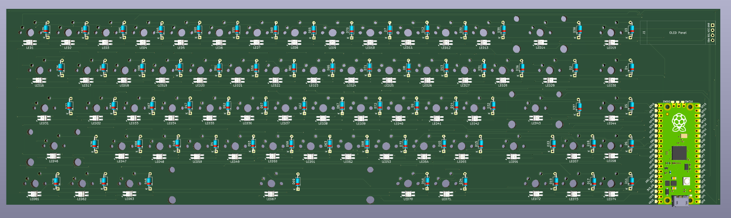
So first lets get all of the models in. The diodes all were in the right place in the models I just had to move them in the pcb design. The leds were all in the right place as well. So first up I added the 3d model for the switches.
To do this I copyed the path at which I had .wrl file and then open each switch in the footprint editor individually to do this. There was prob a way to do this quicker but I just locked in and did it all. next i put the footprint for the stabs around the keys that needed it. And then lastly I the .wrl file for the oled display. I also added keycaps for all the keys except the space bar becaus i coudn't find a 6u .step file.
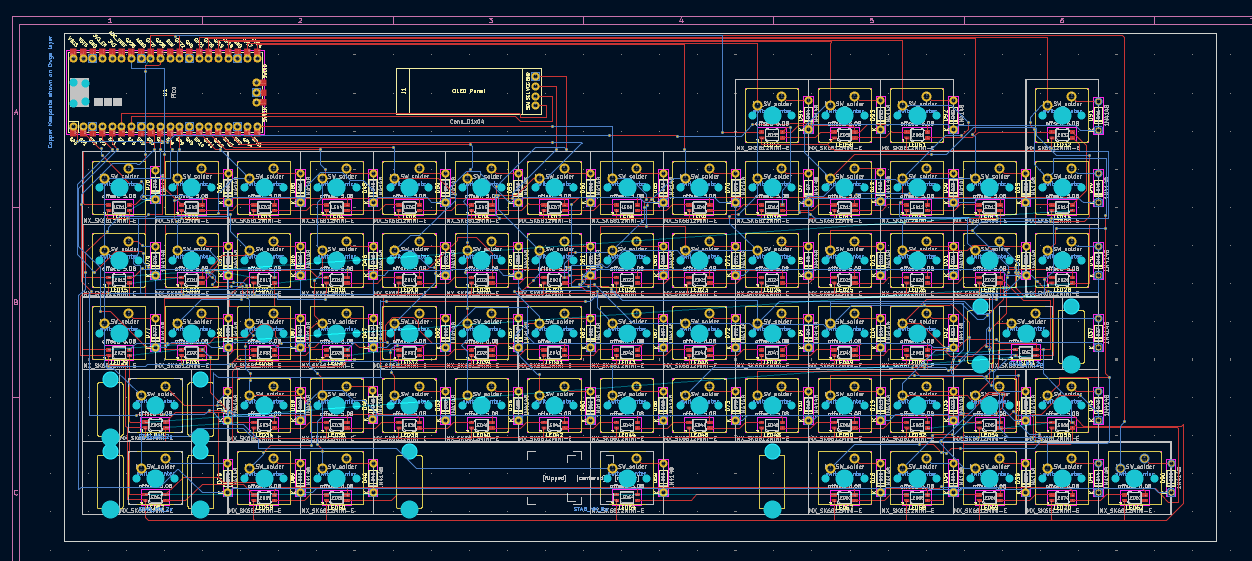
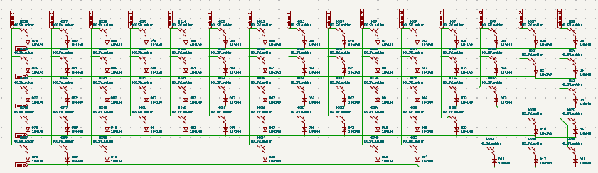
Next I will wire everything up. First up the leds, I just made a staight lines in each row for the power and gnd and then connected thw two ends on either side to the row above and lastly the top row with the pico. Then I wired the din dout according to my schematic with the three sections that i made (wasd and arrow keys, all alphanumerical keys, and modifier keys). Next I wired the swichtes up, the keys were wired in a vertical line and the diodes in the horizantal lined and lastly each key wired to its designated diode.
After I finished this I felt very energized and decided to tackle the code part next. I started by installing qmk on my wsl and then making a new keyboard. Next I edited the keymap.c to the following
and also added the following macros.
This probably took me the longest because I haven't ever coded in c before but also because of the fact that in qmk you don't really code (except of macros) you just tell it which key is where and what it does. This reminds me that I also had to edit the keyboard.json to the following
Thats all for today see you tommorrow
June 22
Time Spent: 5 Hours
I took a very long brake in between because I was working on another project called Mini-Safe but eventually decided to come back and quickly finish this project. So I realized that qmk only supports one rgb strip and I have three so I decided to redo the wiring for the pcb again.
After that I had another major realization. I choose to have a very strange set for the sizes of each key which are generally not supported. This is why I had to change my layout to a supported sizes such as a 6.25 u space bar instead of a 6u one.
I had to change up the keyboard schematic a bit so that it matched the new plan for the keys diodes and the leds. Next I had to put all of the footprints in the right place which is really not a big task but I wanted to make sure that I put all the leds right with precision and accuracy. This was a problem becasuse while placing the keys I used the grid that we were instructed to use in the hackpad buide but for some reason they wouldn't go right on top of each other no matter what I did so I had to just use a smalled grid.
After I finished putting all the compnenets in the right place it was very late and I was tired so I went to sleep.
See You tommorrow
June 23
Time spent: 3 Hours
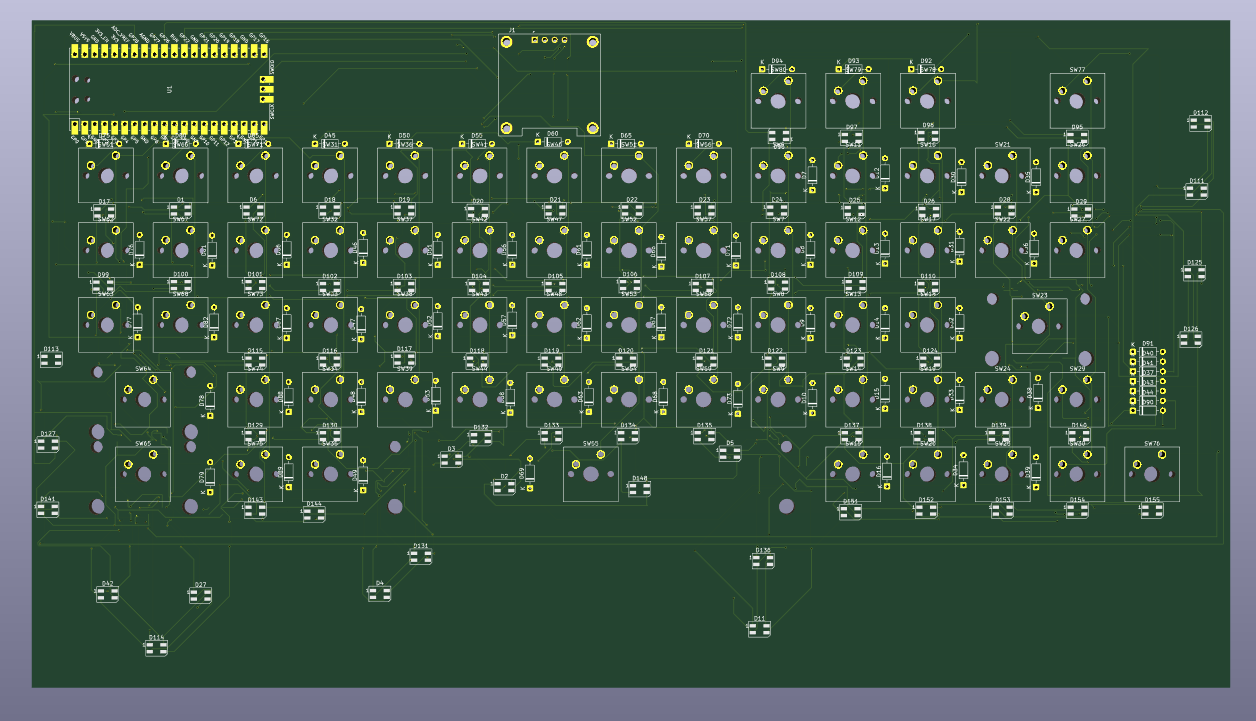
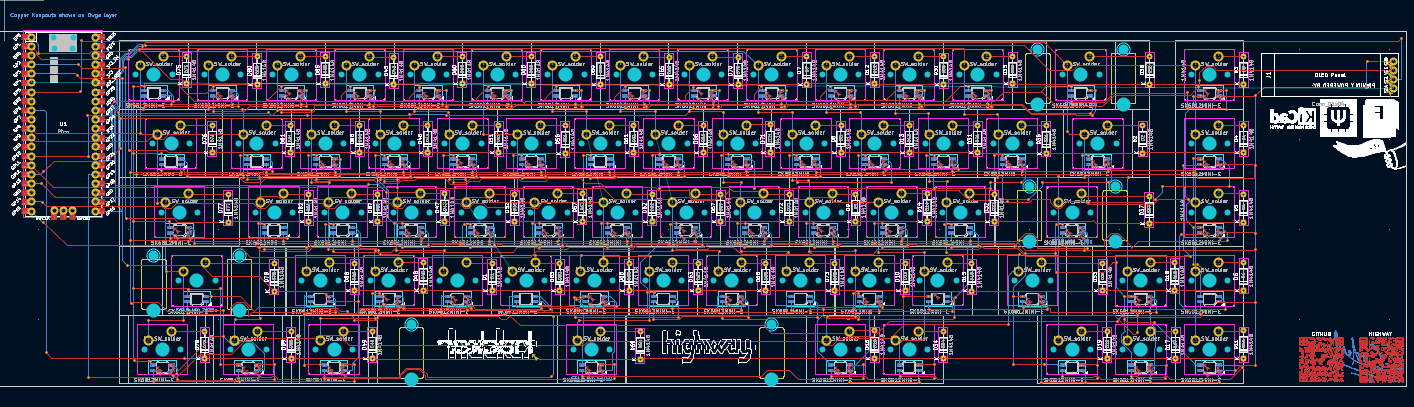
Today I worked on wiring the pcb. I started of by wiring the keys together in columns and then connecting each key to their respective doides. Next I connected each diode to with the othere diodes in their respective row.
Although I did have to make a change after wiring probably around half of the keys vertically. This did cause me some annoyance but the problem was a quick fix so I quickly moved on. The problem that had occured was the I had chosen the 1.75U footprint for the left shift keys instead of 2.25 Which was a pretty easy fix I just had to change the footprint and the wiring around it a little bit.
After I finished that came that hardest part of wiring, the leds. Even though all you have to do is chain them the fact that they are smd and that there are sooo many of them just makes it a big hassle to do. But eventually I finished it again and hopefully I will not have to do this entire thing again.
See You tommorrow
June 29
Time Spent: 10 Hours
Today I am gonna work on the firmware for the project. I am gonna use qmk to do this and I did start this a little bit before but becuase I changed the layout of my keyboard I had to also change my code from scratch(Yaay!). So I first started of by reading the the qmk docs. After that I had a somewhat good idea of how to start of so I made a simple keymap and keyboard.json file for my keyboard.
After that came probably the most difficult part. Adding the Oled. This is because there were so many cool features I wanted to add such as pictures and animations and so much more. So I decided to add a startup animation that would show the qmk logo and some hackclub branding. I originally wanted to show some highway branding but was unable to find a black and white versions so I settled with Orpheas Flag.
I also added a cool easter egg animation for hacking the host computer
. Another thing that I wanted to add but was unable to was a matrix rain screensaver that would activate while the computer was in screensaver mode.
Lastly I used the screen to be able to tell my current WPM(which is usually in the 50s), which layer I am on, and wheather my caps lock is on or not.
I also added another layer to my keyboard as it would be the one that contains all of the MODS
. This is where you can contol rgb animations, hue, sat, val(speed of animation), Volume, Skip forward and backward tracks, and go to boot mode. Something that I though was soo cool was Velocikey.
Velocikey allows you to change the speed of your rgb animations with the speed of your typing. That is so cool. I was absoulutly blown away by this and imediatly added this to my keyboard. I stil had to add the rgb lighting though. This was surprisingly easy companred to all the stuff I had todo on KMK with my last project. All I had to do was add the neccesary commands on rules.mk and config.h then add all of the rgb animations as keycodes.
Now its time to show you the code My amazing keyboard
It took me a really long time to do so I hope you like it. :)
Also I found this vid very helpful while coding the oled Amazing Very Helpful Video About Oleds on QMK
bye
June 30
Time spent: 7 Hours
After yesterday I thought that I was atleast 2/3 done. I had finished the pcb and the code for it so I just had to do the case. Little did I know that I was wrong. The footprint I had used for the leds looked wrong now that I took a closer look. The footprint would be right if it was on the back but for some reson if was on the front. This is why not that I tried to get the sk6812 3d model I couldn't get the notch on one of the the legs lined up properly. After this relavation I decided to find a better footprint, and I quickly found one suprisingly by the same person in a newer repository.
I quickly downloaded the repository as a zip and added it to my library table on kicad. Next I had to replace the symbols on the schematic, I had to do this because the pin numbers on the new footprint were in a different order. I very quickly did this and assigned each symbol the correct footprint so that I could now import the new symbols into the pcb editor and start wiring. First I deleted all of the old leds and replaced them with the new footprints. Then I started to wire them. This took me a really long time. I don't really now what to write here cause all I'm doing is wiring the same thing that I have already wired like 5 times before. I wired the 5V Gnd DIN and DOUT to their respective locations.
I also moved the RSP PI PICO to the top left isntead of the bottom right, this is becasue if it was on the bottom then I would have to use a very long wire and the wire would have to go all the way across the board and to get to the computer but now that its on the back it should make things a little bit simpler. I'm done, YAY(for the fifth time).
Now that I was finished with the pcb and firmware(as well as the fact that it was 11pm) instead of starting the CAD model right away I decided to add some silkscreen to make it look cool. I added the logos of KICAD, QMK, Fusion 360, and Orpheas holding HC flag with the words Proudly Powered By:
, I also added some ASCI art such as the words HACKER and HIGHWAY and some qr codes for my github repostiory and the highway website. I am probably gonna add even more stuff because I have a ton of empty space.
ALR bye tommorrow I will work on the CAD model
July 4
Time spent: 5 Hours
Today I worked on and finished the CAD and it didn't really take me to long to do as its really just what I did for the hackpad at a bigger scale. I first made a sketch for the bottom part of the case. I took the measurements from kicad but I will also import the step model just to be safe. After I did this I realized that the keyboard is way to big (407x1145mm) to print once so I split it in two.
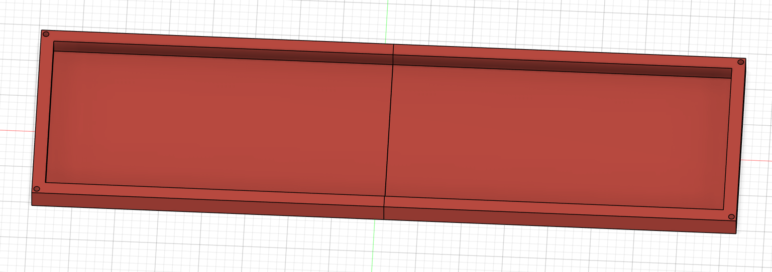
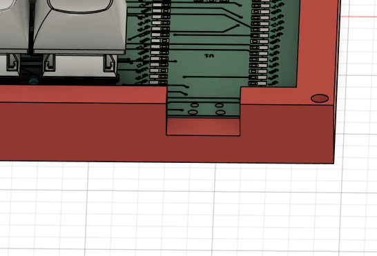
I also had to figure out how I would keep the two sides together and I decided that the best way to do this would be to add more m3 screws. So I made a hole on the sides that would only be visible from the inside for the screws.
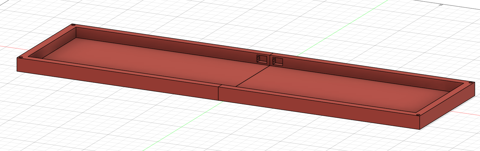
Note: you can see it in the middle there and it is like this on both sides
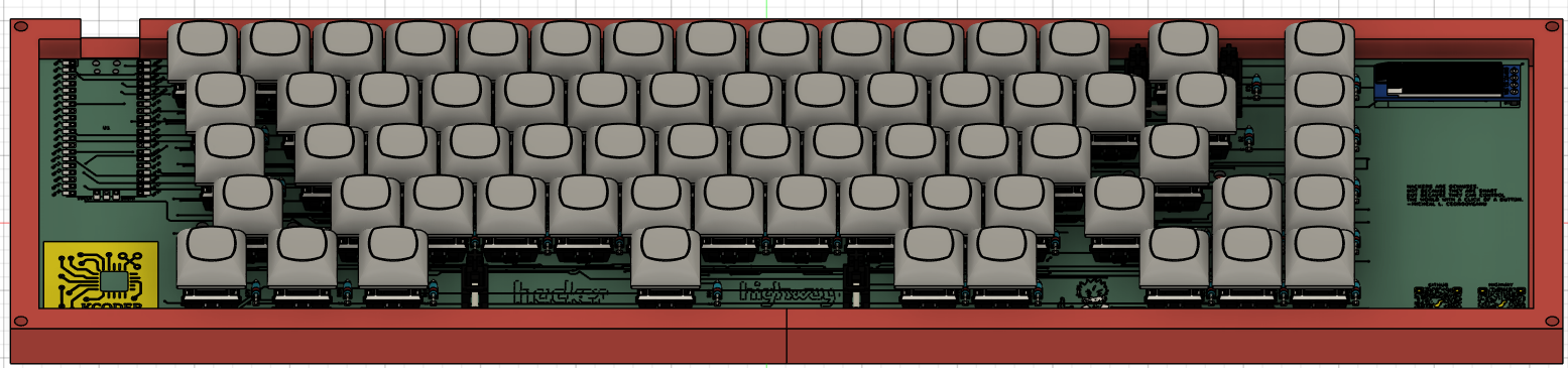
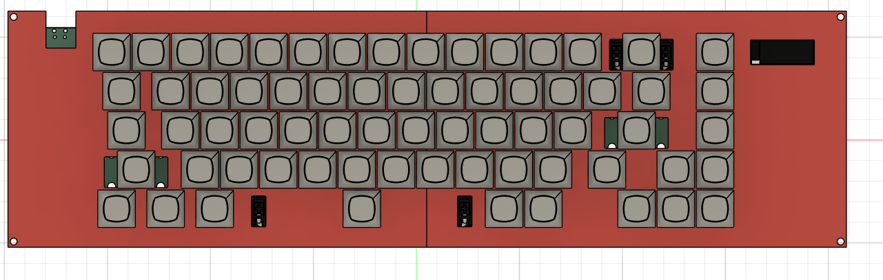
Next I imported the pcb to see if it would fit. And it did. it had roughly 6mm space on the top and bottom and 3mm on the sides. This is should be fine becasue it will fit in and not move once the bottom and top plate have been attached.
Next I made the top case using a dxf file from aio3's website. I also kept the screws that connect the top and the bottom to be m3.
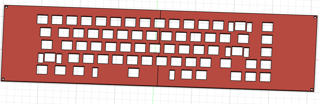
After that I made a hole on the case for the power wire and also the oled display.
Lastly to connect the two top parts I added more holes for m3 screws.
I also made sure that it doesn't overlap with the top of the pcb as you can see in this image.
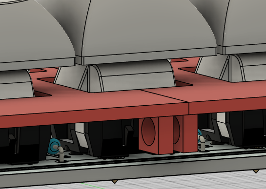
Note: Its like this on both sides.
And That is it. really its over I can't believe it. It has taken me so long to do this and its over. finnally over.
July 24
Time spent: 45 mins
It would be finish if I hadn't made some stupid mistakes such as 1 of the images in the readme was older and didnt match up so I had to replace it. I was told by @Logan Peterson that the qr codes would not work so I replaced them with silkscreen and made them bigger. I also removed the pcba from the bom as I was told that I couldn't do that for my leds.
Next all I have to do is improve my case. I was actually thinking about doing this but didn't do it as I has already submitted my design so now I get to make it better. I think first up I will add a fillet around the corners and then engrave some cool designs into it.
I first of started by adding the hackclub and qmk logo then added the name of the product and some other words on the other side. This took me roughly half an hour to do along with fixing the issues on my repo it added up to 45 mins. I checked back on the list of things I had to fix and that was it!
I am done!! again. I hope this is that last time and that I get approved now. lets see what happens
is this project gets approved and I am also able to finish all my other projects then I will be able to get a 3D printer!! <-- this is the last project I need to finsish for that!
July 27
Time Spent: 45 mins
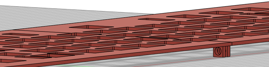
I wasn't able to do that much the past two days but today I finished made my keyboard case look much much bettter. I added slanted rectangle grills on the side as well as triangle on the front and back that should increase friction with the table and also it looks cool. Lastly I also added colors to make it look absoulutly epic.
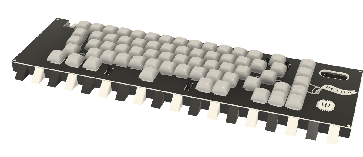
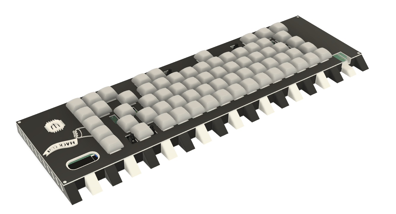
thanks so much!!!