
Chippy CNC
Designing and building a cheap CNC mill using as many random parts I have as possible to minimize cost
Total time spent: 27 hours
5/25/2025 Log 1: Initial Concepts
I began by trying to figure out if this is even possible. To get my ideas flowing, I made a quick Google doc with each part of the CNC as I thought of them and explained how I would fulfill that requirement: either with parts I have or links to a cheap option I could use.
I set up this repo, made an Onshape document, and my research document above. I'm doing my best to fit into the $150 price tag to avoid the extra bar for $350 funding, but I may apply for it as necessary in the future. It would certainly be a huge upgrade to the machine, but the goal is a minimum functioning product for as little as possible.
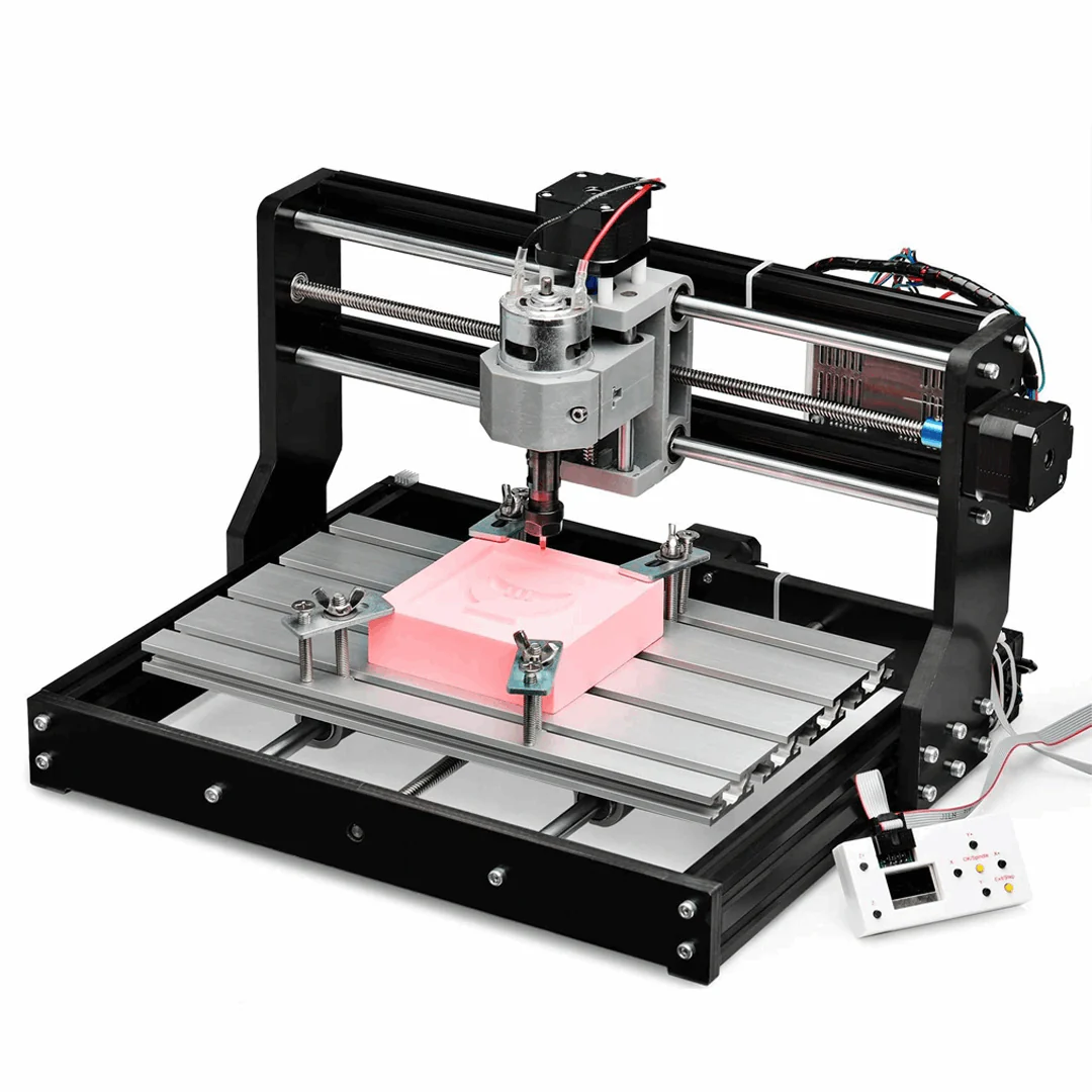
I'm looking to follow a basic CNC configuration with the spindle moving in XZ and the bed in Y, much like a bedslinger 3D printer or a 3018 style CNC.
Time Spent: 45 Minutes (mostly research)
5/25/2025 Log 2: Ideation
Some parts are not in my house at this exact moment so I need to wait a few days to go and grab them. In the meantime, I'll try to design most of the printer and be able to swap out the CAD models as I get the real ones and create/find models for them.
It is also worth noting that I have access to an Omio CNC router through my robotics team, which will enable me to make custom parts in aluminum or polycarbonate as I please (though I may have to buy stock as part of my budget). I also recently set up a 4th axis on it, so I can even do some more complex parts too.
Here are some sources of inspiration:

Time Spent: 15 Minutes
5/26/2025 Log 3: More Research
I can't get some of the parts that I need until tomorrow, so I'm mostly holding off on CAD work until then to avoid extra work. In the meantime, I'm continuing to look into how I'm going to put this all together. I'm currently examining GRBL-Mega, since I have an Arduino Mega with some sort of motor driver hat that hopefully is compatible. I also have a random Raspberry Pi 3B that I could use as a standalone computer for the CNC (just so it doesn't have to sit next to my real computer). I'm doing as much pre-requisitve research as possible while I wait for those parts and so I don't waste time doing something that isn't possible (or I know where to put more of my budget). So far, the main budget items I have planned for are a spindle (cheapest one I could find is $27, the 3018 type spindle with an ER11 collet), a fixture table that I will likely make myself on the Omio CNC, stepper motors, and possibly a second ball screw of the same model I already have (~60, comes with a motor). Again, I'm hoping to stay under $150 but I may expand beyond that to accomodate any necessary parts for the functioning of the machine, or add more features like probing, an enclosure, or a better spindle.
Time spent: 45 Minutes
6/02/2025 Log 4: Finding Parts
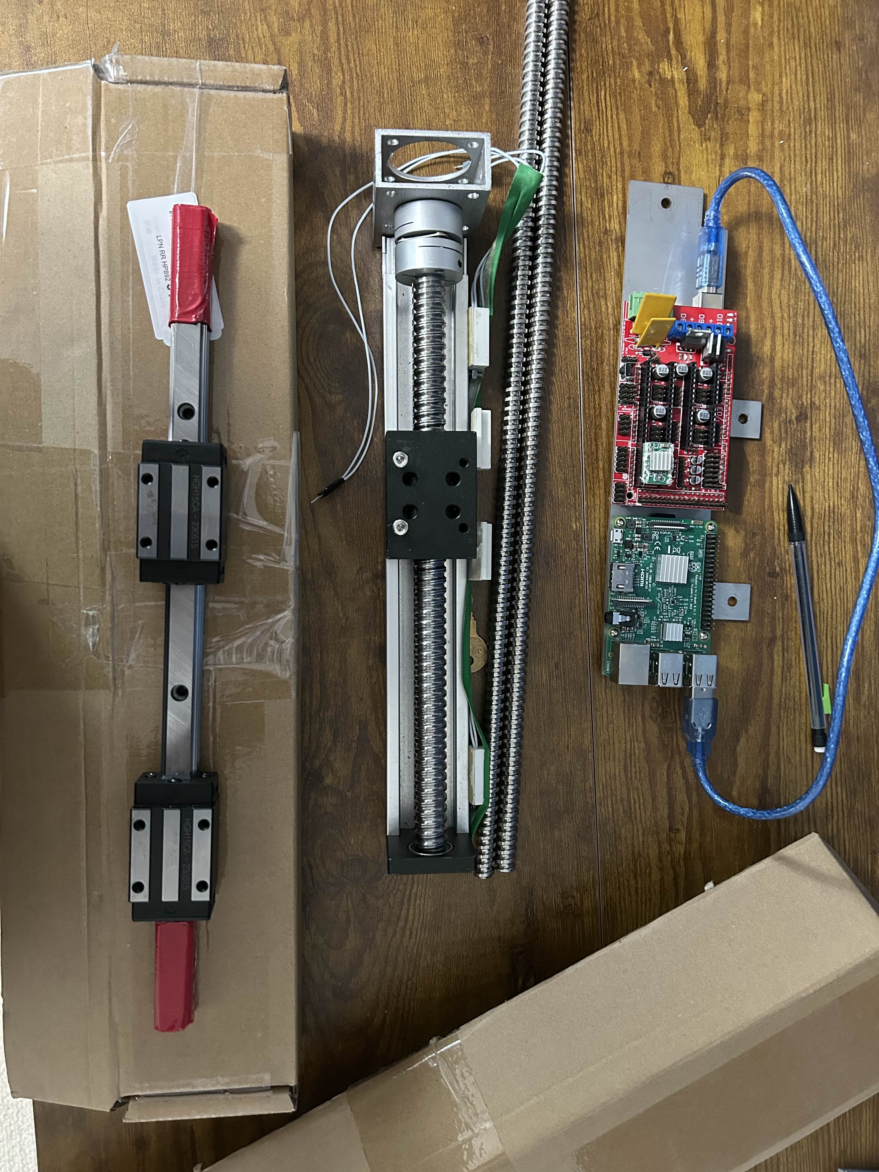
Most of this past week, I've been busy with the end of the school year, but I still took some time to get together all the parts I currently have and what needs to be purchased. To recap, I have two 400mm ball screws without nuts, four 350mm HGH15 linear rails, a RATTMMOTOR CBX 1605-200mm Z axis without a motor, and have since determined that the Arduino Mega with the Reprap RAMPS V1.4 sheild I have will not work as it is more suited for 3D printers and doesn't have the power to run a spindle. With these decisions, I am currently leaning toward this control board, two of these ball nuts, and finally this power supply and spindle combo, which I know will be compatible with the chosen control board.
Of these, my biggest concern is the spindle, as it is quite small and has a high risk of lacking rigidity. I really just want this to function, so even if it is very slow or only mills soft materials, I'll be happy and can expand upon it later. The total cost for these parts is around $105, leaving me only $45 left in my budget to purchase any other components like the stepper motors, structural hardware, limit switches, wiring, and other necessary components like shaft couplers, bolts, etc. Because of this, alongside the potential for a significantly more powerful machine by spending just slightly more, I am likely going to propose my project to the $350 budget range in order to make this viable.
Time spent: 1 hour (over the week)
6/03/2025 Log 5: Beginning Design
Given that I'm starting with many parts on hand, I'm getting 3D models of them where possible. I was able to find a model for the spindle, linear rails, and ball screw nuts. I also whipped up a model for the lead screw in Onshape using a helix curve and a sweep toolpath with a 2.5mm circle and a 5mm pitch helix. Unfortunately, this mainly leaves the Z stage without a model, of which I may need to replicate myself. To minimize the amount of CAD work to be done, I only plan to model the block (nut) on the screw, since those mounting features are the only part of the assembly that I really care about, alongside the back of it which has rails with captive nuts for mounting. With these parts accounted for, I'll now move into more modeling of the machine, based around a few design constraints: the parts I have, using 8020 for structural pieces where possible, and doing any custom parts based on 1/4" plate as I have access to it in small quantities.
Separately, I've tentatively decided on this 3-pack of NEMA 17 stepper motors that should be compatible with the control board as well and are quite cheap at $26 for all three. I have added the associated 3D model to my Onshape document as well.
Time spent: 1 hour
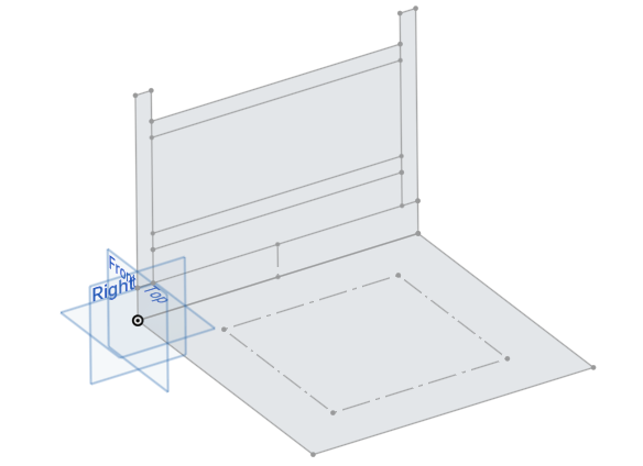
6/04/2025 Log 6: Base sketches
I did out some sketches in Onshape, making this as parametric as possible. I'm using some variables to name certain values like the length of my rails, ball screws, and the gap between the table and the spindle (Z-gap). I'm taking the time to think through these sizes and constraints to ensure they will propogate down correctly later on if I need to change things. I also made a small subassembly for the linear rails with limited slider mates on the blocks.
Time spent: 30 minutes
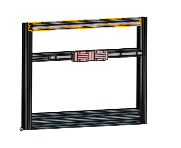
6/16/2025 Log 7: More Onshape
I worked out the back of the mill, which is the X axis and will hold the Z axis on it. I'm starting very simple, with some 8020 extrusions going around and some 2x1 ones at the bottom to give me some space for the rails and ball screw on the Y axis. My main issue with this was that the 8020 featurescript in Onshape is really difficult to use, as it generates facing straight up all the time. I spent quite a while trying to figure out a workaround and eventually settled on a not-ideal but somewhat parametric way to get the lengths set in the part studio.
Time spent: 1.5 hours
6/17/2025 Log 8: Onshape Struggles Continue
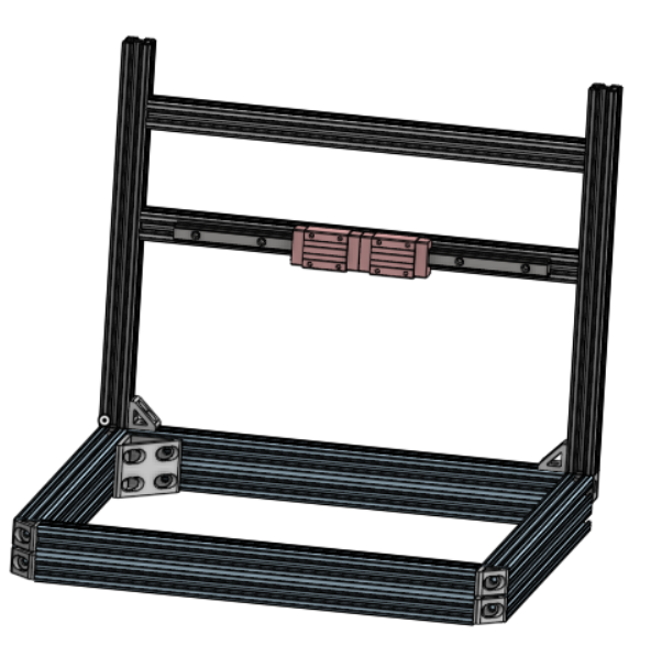
As I build out the rest of the machine in Onshape, I am beginning to really hate the 8020 featurescript and even using it as a part in CAD. Since it has rounded corners, I cannot add mate connectors to the corners exactly and instead have to use some strange face mates to connect the pieces. After discussing these issues with another Hack Club member, he recommended I simply model the 8020 as a solid 1x1 inch box, which I will convert now before the design gets too large. This means I will basically have to re-do both the part studio and assembly, but it will make things much easier going forward. You can also see some corner braces and attachment methods being added, though they aren't completely cadded in yet. I have some small 1x1 corner brackets, large 2x2 brackets for the inside of the base, and square pieces that are meant to attach three tapped 8020 extrusions in the corners (more details to come). Let's get to the conversion!
Before pic:
Time spent: 1 hour
6/18/2025 Log 9: Onshape grind + Rethinking the machine
I'd like to touch on that rethinking part first: I was initially trying to hit the $150 price point Hack Club offers, but after reviewing the guidelines more closely, I believe this is likely to fall into the advanced $350 category. For this reason, I'm looking at possible changes to my spindle (easiest) or even to the control board, drivers and motors (harder). The spindle is a straightforward upgrade with the same controller up to a 500W spindle, which makes it an ideal easy solution. However, the main limiting factor at this point would be the stepper motors I'm using to drive the whole machine, which are limited to 2 amps of maximum current based on the A4988 drivers the control board has. If I choose a different control board without integrated drivers, I could increase the power of those drivers up to 4A or higher, giving me room to put on larger stepper motors that will make the machine run much better. I will be continuing to consider this option as I move forward with the design, as it should not be heavily reliant on this choice.
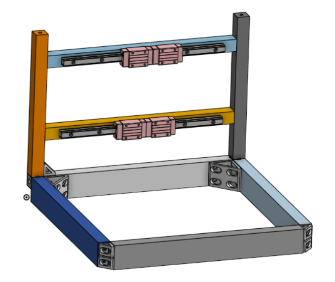
As for Onshape, now comes the time to re-do all the 8020 extrusions to be simple boxes for ease of design. Here is what it looks like after:
Naturally, after doing all of this, I began rethinking my work from the start. I'm now realizing it could be easier for the operator (myself) to use if the bed is completely stationary and the spindle moves in XYZ, much like a typical cnc router. I will also be considering this as I continue working, and might create a branch in Onshape to test this out if it appears to be desirable. I am still unsure how this would complicate or simplify my ability to move each axis with the ball screws, which I am yet to figure out exactly in either design. I may replace some 8020 sections with 1/4" sheet aluminum milled to my specifications (on the router I have access to). This is likely to be more expensive, but may produce better end results.
Time spent: 1.75 hours
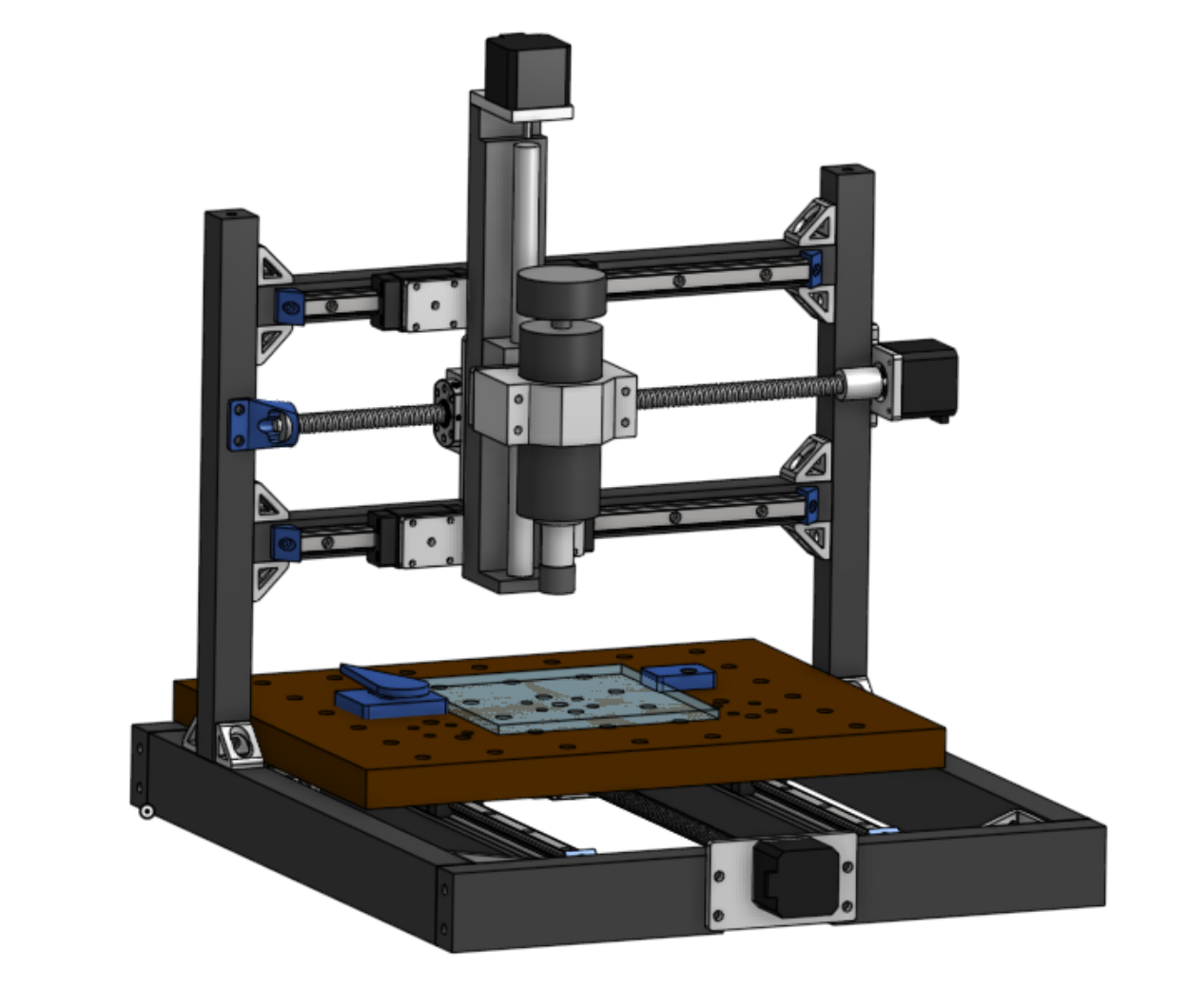
6/19/2025 Log 10: Big progress
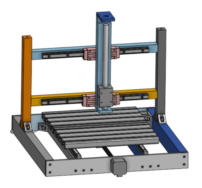
Today I really locked in on cad and got a lot done, fixing many issues and continuing the design phase. After much thought, I stuck with the bedslinger style of kinematics (XZ on the head, Y on the bed), but realized that the XZ section must be centered on the mill to reach all of the millable area. I also replaced the front and back of the machine with 1/4" aluminum plate that I will mill out, simplifying the design by allowing me to easily mount the motor that drives the Y axis (pictured in the grey motor below). That said, I'll probably re-do it again to have a smaller mounting plate because that one is massive and impractical.
I continued at sorting out the core kinematics, first by adding some 40-1620 8020 extrusion as a bed to the printer. My hope is that this will make it easy to clamp parts and add a spoilboard on top. The main downside is cost, at a whopping $60 for the build plate pictured. I will keep in consideration another spoilboard mounting solution as well as possibly some way to add a machining vice for larger 3D milling operations (possibly a way to detach the bed and add a vice directly to the linear rails?)
As you can see, I got around to creating a 3D model of my Z axis to continue figuring out my placement for the spindle motor and X axis power. In an ideal world, the X axis ball screw could run between the rails, just behind the Z axis assembly to increase rigidity. Doing so may require some kind of custom motor mounting plate, which is certainly fine within the scope of this project.
Time spent: 3 hours (honestly much more but let's just count 3)
6/20/2025 Log 11: Keeping it Moving
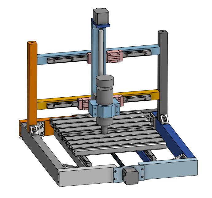
I redid the front and back again to use smaller milled plates, though I may even make the back a single piece of extrusion as it isn't entirely needed. I got around to creating models for the spindle and the clamp it comes with, which will need some kind of adaptor plate to the Z axis. I'm getting relatively close to a point where I can begin ordering parts (aka submitting to HC), so I'm super excited for that! The major tasks that remain are the X axis power, creating various mounting plates and adaptors, and sorting out smaller details like modeling in bolts where needed, adding shaft collars to the motors to connect the ball screws, etc. I already have most of my plans sorted out for the controls and such, which aren't currently modeled as it doesn't really make a functional difference just yet. Here's the progress photo for today:
Time spent: 1.5 hours
6/27/2025 Log 12: Tidying Up Loose Ends
This log will cover the small pieces I've been doing over the course of that last week (I've been busy so it's all clumped together). First, I found that I can buy ball nut housings for quite cheap, giving me a strong aluminum connecting piece for X and Y power. However, the threads they come with don't match perfectly with my other parts so some adaptor plates were made too. Here's one of them on the X axis power:
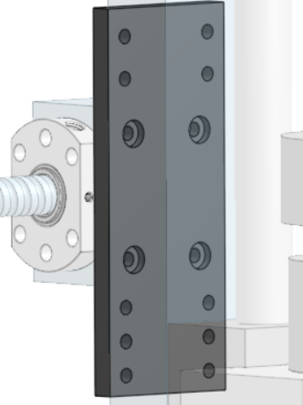
The pockets are countersinks for the bolts going into the block, while the holes above and below are for the slots on the Z axis.
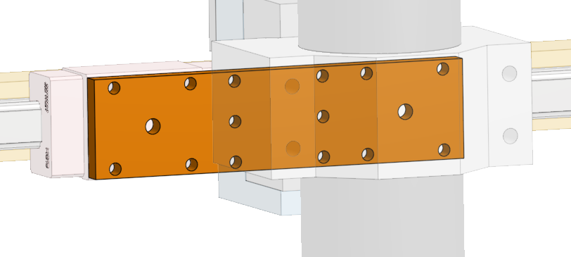
I also made some plates to mount the X axis rails to the Z axis, which are nice and simple: they keep the two carraige blocks close as to minimize any reduction in travel distance while also maintaining rigidity. I will do the same for the Y axis soon. Here's what those look like:
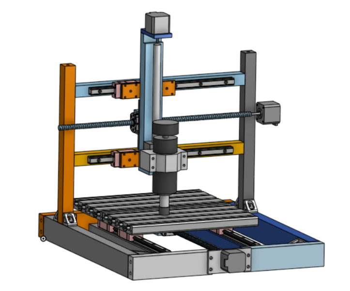
Here's what the full assembly looks like at the moment (note: the X axis motor plate is modeled but not in the assembly yet):
Of course, there are still many small pieces to figure out! One big thing is changing out the bed: I want to change it from that extrusion (very expensive for what it is imo) to a simple spoilboard (which I need anyway). This way, I can simply have holes drilled to bolt directly to the linear rails and the ball screw (no adaptor plates), as well as some kind of hole-based clamping system like this one. I also need to make 3D printed end stops to the rails, 3DP parts with bearings to hold the ends of the ball screws, and some other final touches. Looking forward to finishing this off!
Time spent: 2 hours
7/11/2025 Log 13: Final Log!
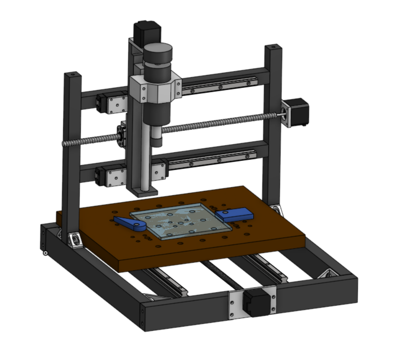
We're just about finished and ready for submission to Hack Club! First some updates since the last note: - Switched to the spoilboard base as planned for cost reasons - Re-did the colors in Onshape to look nicer and be more informative by material - Created the spoilboard clamping system as a clone of Marius Hornberger's design, using 3D printed cam clamps (may be adjusted if too weak in the future) - Completed the BOM with all parts needed for construction
With these, I'm calling the project done! I may need to make some minor adjustments later on as I run in to issues and such, but for the time being it's all set. Thank you for reading and to Hack Club for providing this opportunity!
Time spent: 5 hours (mostly finishing BOM and writing this/the readme)
7/12/2025 Log 14: Oops not final log
Well, I realized I was certainly not ready for my actual submission, as this has to be 100% fleshed out before review. First, I made a relatively large change to the printer by choosing to purchase ball screws as it costs a total of $20 more and my current ones don't appear to be a standard size. I don't believe it is worth the risk to buy ball screw nuts only and pray they fit the ones I have. Instead, I'll be purchasing 400mm ball screws with machined ends down to 8mm (allowing me to use 5mm to 8mm couplers), spending a bit more but preventing a possible failure of the project. This change also made the extrusions standard sizes of 450, 400, and 350mm across the board, which honestly doesn't make a huge difference as they must be bought cut or cut yourself regardless, but it's a nice addition. To touch up everything, I added 3D printable end stops to the linear rails to prevent them from falling apart, modeled in the shaft couplers, and added 3D prints and bearings to the ends of the ball screws to ensure they are supported.
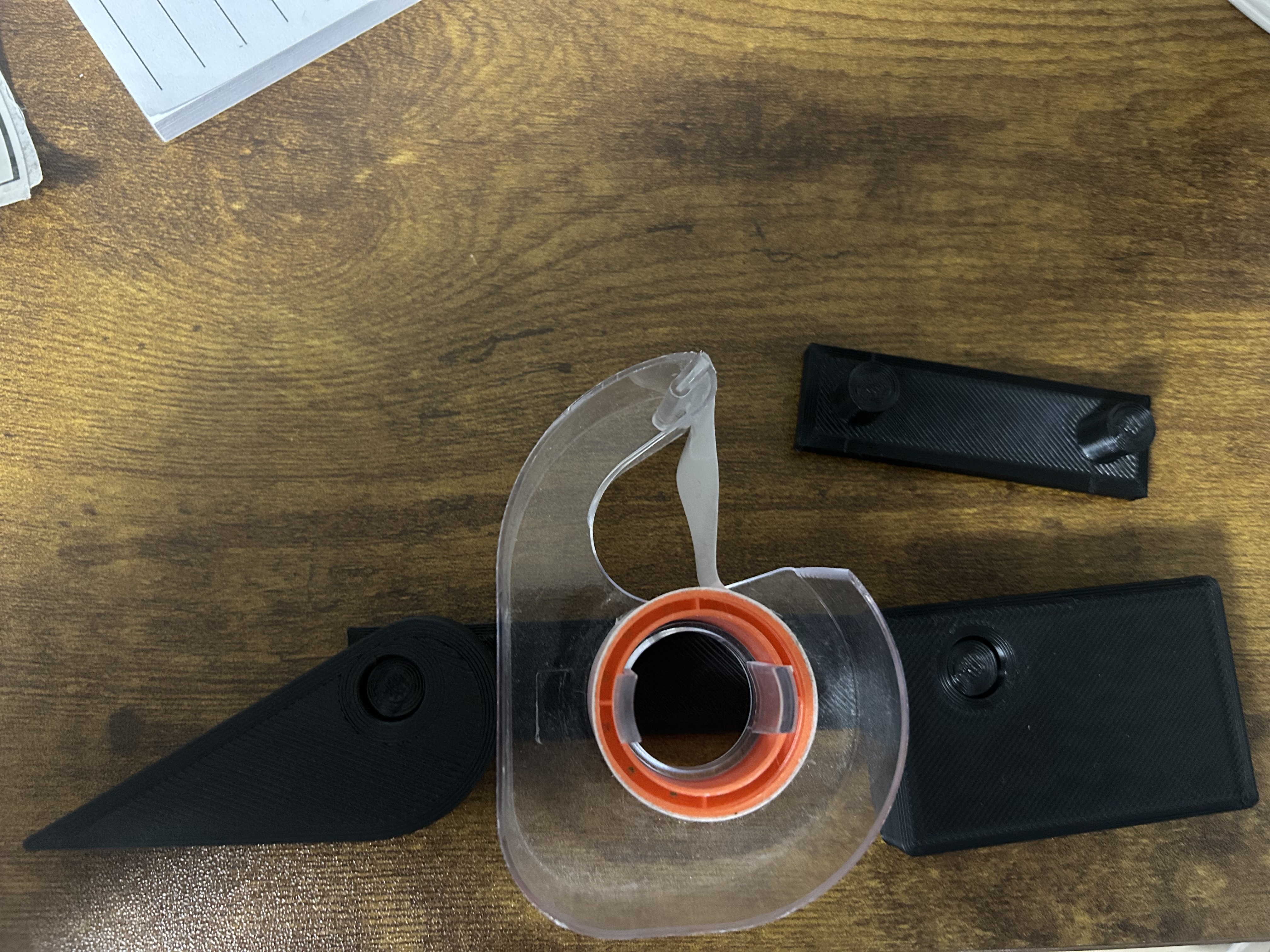
I also began printing out some parts to check their compatibility and function, as well as a simple test jig for my clamping method. When holding the lever, the clamp is quite strong, but it seems to naturally fall back to a rest (no force) position when letting go. Based on the video from above, the original creator mentioned that the travel on his clamps was 12mm
which is quite a lot
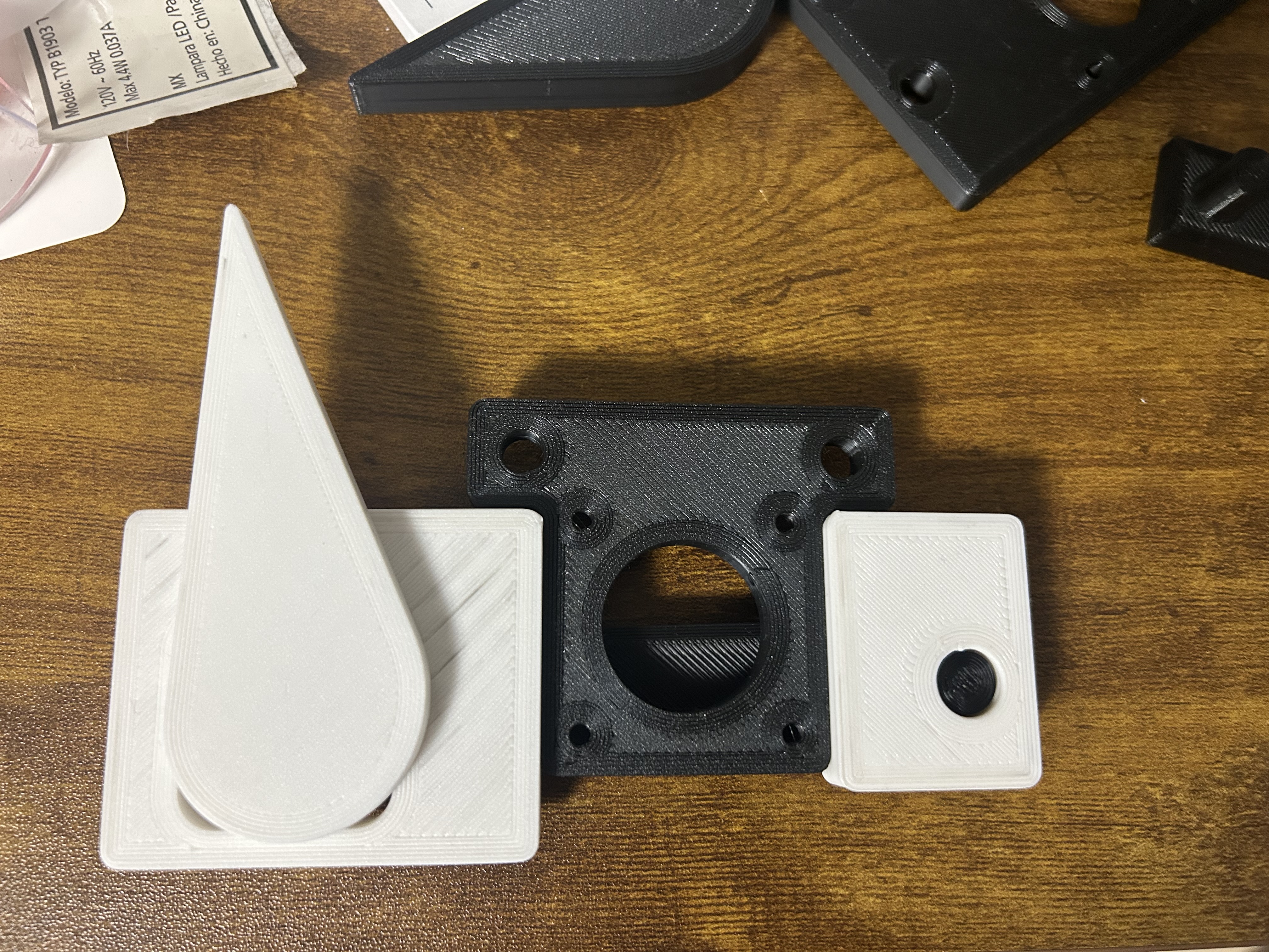
. Mine currently are modeled as 13.75mm of travel (a specific size based on my hole spacing, which I will change after seeing it in real life regardless), and my clamps seem to be significantly smaller overall as well. Because of this, I designed a version with significantly reduced travel distance to apply a larger force. I thought I could get away without having spacer blocks on the cam lever, but now realize that is part of what allows you to get greater pressure on the clamp. Here's a picture of how my old model looks in real life:
I will soon print out a new test jig with the new clamp style and see how it fares. Hopefully all goes well! Other than refining this, I believe pretty much everything is set on the design front for now. I could add some kind of enclosure, but that's a project for another day as it definitely won't be in the budget :) I went ahead and updated my BOM to match all my changes, and I'm looking forward to actually being done soon!
P.S. the new clamp style worked!! Here it is holding another plate quite securely. That spacer block and lower travel was the trick!
Time spent: 6 hours
7/17/2025 Log 15: Actual final log until revisions
I already submitted this project and am awaiting review, but I quickly added in a scaled down model of a typical CNC style vice to approximate what my real one would look like (since no dimensions were given). I did so by finding a similar looking model online and scaling it down until the hard jaw was 3 inches across, as mine would be, and just eyeballing the slot positions compared to the provided images seemed about right. I made a fixture plate to attach it so that I can switch between using the spoilboard and the vice, and added Onshape configurations to reflect this idea. Here are the two setups:
Spoilboard:
CNC vice:
Time spent: 1 hour
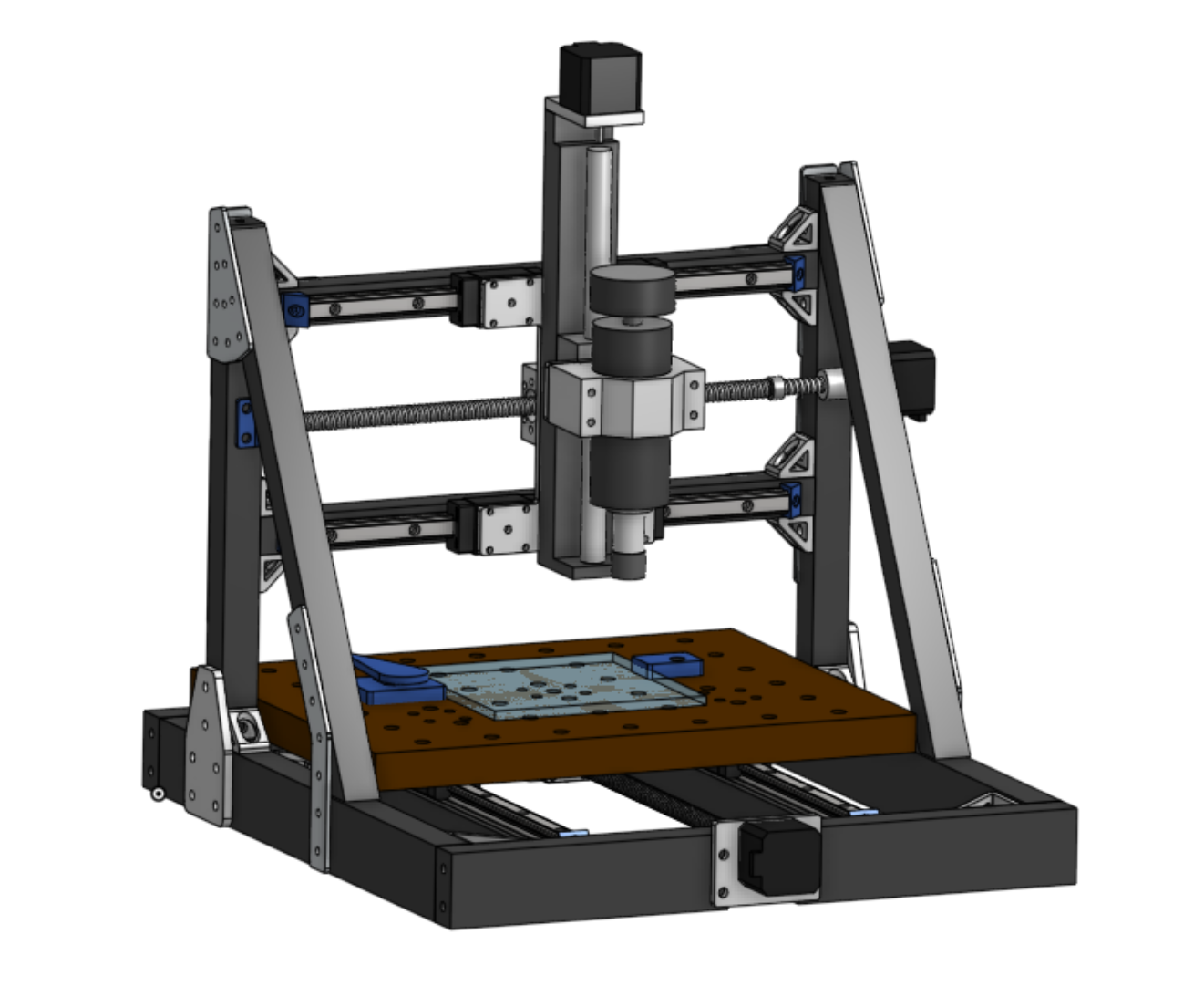
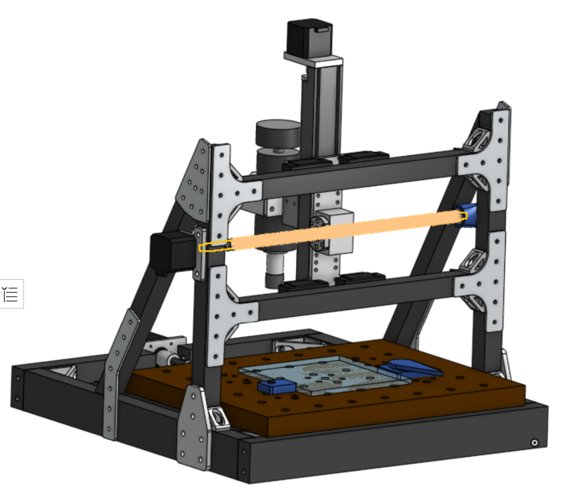
8/5/2025 Log 16: Post review Log
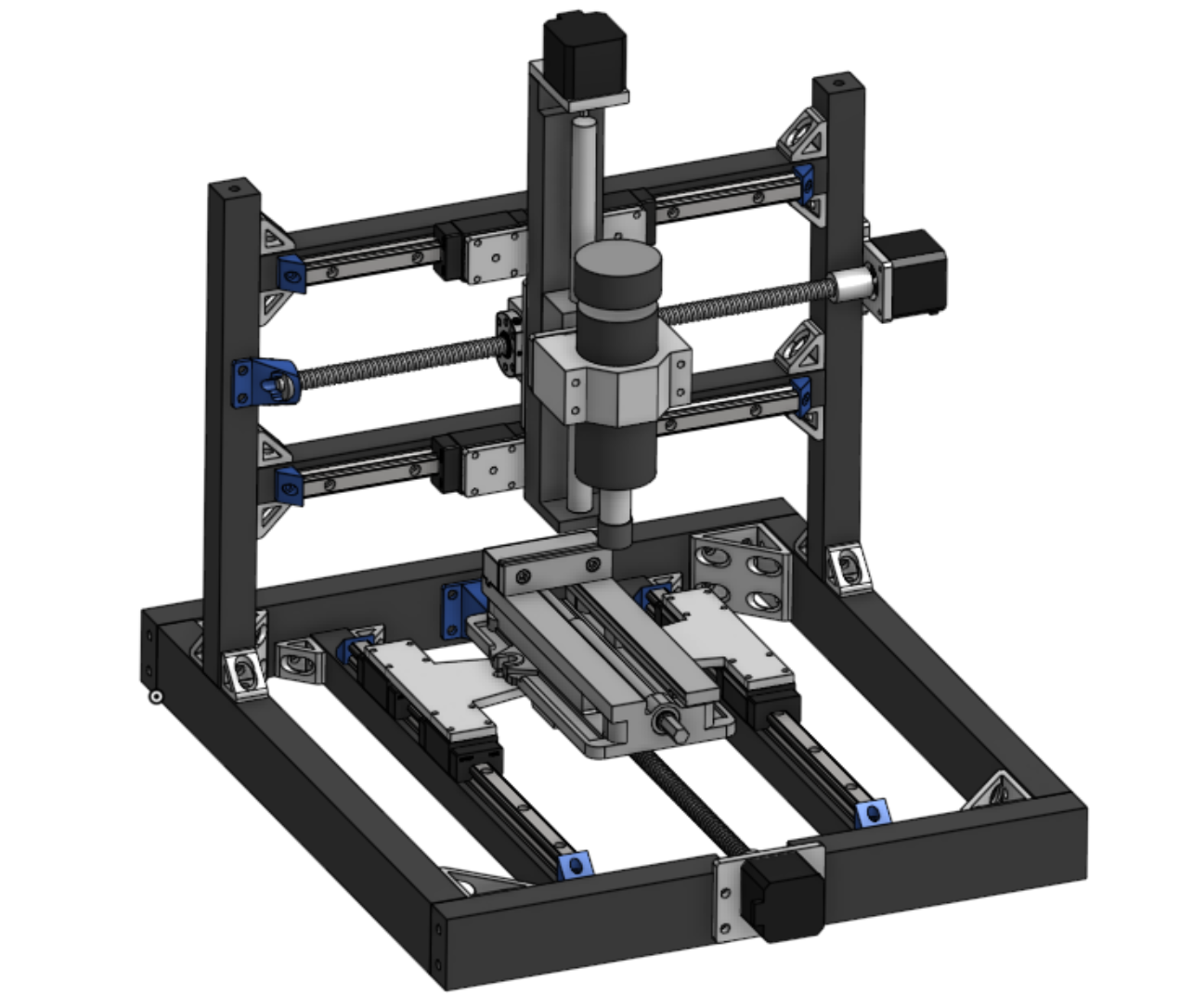
In my review, the main concern was simply rigidity: I designed an all aluminum extrusion frame, since I simply have it, but the reviewers were concerned this may not prove rigid enough for CNC, at least in the small pieces going up to the X and Z axis. To rectify this, I added some slanted braces of extrusion and many more gussets (both off the shelf and custom) to these areas. I also combined the 3 Z axis plates on the rails and ball screw into one mega-plate, hopefully increasing the rigidity of that setup as well. The plate is still reasonably small enough to machine, which was my initial concern in doing so.
The best part? All of these modifications barely increase my total, as these are also parts I have access to (the gussets and such). The bearings for the motor-side supports must be 10mm ID instead of 8mm so those have to be added on, but that should be a small cost compared to the overall machine.
Time spent: 3 hours