
multi-tool
A small pocket-size gadget that features clock or compass, with more features coming! It's built for hiking and is designed for ultra-low power.
Total time spent: 26h05m
July 12: Project outline and components
I've created this github repo and settled down on what the final projet should look like. I've had the project visioned for a some time, but i've started now building it.
I want it to be a something like smart pocket watch. It should have clock, compass, also a gps for distance tracking. The watch would be built for use in nature, so it needs to be really power efficient, because charghing availability won't be big there. I'll be using it on trips that will be several days long, and I hope I could use this gadget for tracking my trip and general usage there. I imagine it would have a rotating wheel and a button. I think this would be sufficient for all ui navigation.
Part selection
Microcontroller
I needed a very small one, that would also have a low power consumption and would be powerful enough to handle a desplay and several modules connected to it. After a quick search I chose the arduino pro mini, but later i've discovered the Seeed Studio XIAO nRF52840, which is way smaller than the arduino and has much better specs. It has 256 kB of ram (arduino has only 2kB!) and similar goes for flash storage. This microcontroller has 3 MB of flash memory in total, while arduino has 32kB. And it's only about 2x more expensive, just for $6. This is just the winner for me and I'll be comfortable knowing I have the specs for more intensive tasks. And as a bonus, it has a charging module built in! Maybe only problem that could occur is the number of gpio pins, which is 11, but i'll try to solve this by using i2c for sensor modules.
Display
I've initially wanted an e-ink display for it's readability on sun and also just cool looks, but i've found out that nobody is making small and square displays, which is what I need (and if there are, they are very expensive). After a bit of research, I know a small and grayscale oled would be perfect. It would be power efficient and also will have a cool retro look to it. But it took me a while to find the perfect one. First i've looked on Waveshare 1.5inch OLED Display Module, 128×128 Resolution for a while, but i've felt that it is just too big. But then i've found the Waveshare 1.32" OLED (128×96, 16 grayscale). I will need to move a rezistor on the display to switch to the i2c communication, because the default SPI uses too many pins, as I've realized later when picking the gps and rotating wheel. It will have 0x3d address by default.
Magnetometer
This module will be used by the compass feature. I've tried looking on aliexpress and eventually found two options: modules using the discontinued HMC5883L chip, or the newer QMC5883L. I eventually went with the newer chip which has a lower power draw. But I will need to keep in mind to use a dedicated code library. The i2c address is usually 0x0d
The assembled module will be: https://www.aliexpress.com/item/1005007183006706.html
Accelerometer + Gyro
This wasn't too hard to find, but on aliexpress on large amount of products there were negative reviews, which was a bit surprising. I've eventually found https://www.aliexpress.com/item/1005008913624575.html and it has 0x68 i2c adress, which is not being used by other sensor.
Real Time Clock
This module is quite essential for my multi tool, and it wasn't hard to find. It will handle keeping track of current time and date. I did a quick google search and found a highly recommended DS3231 module. It has default i2c adress 0x57.
Aliexpress: https://www.aliexpress.com/item/1005007143596890.html
GPS Module
I also want this gadget to have a gps inside it, mainly for trip tracking. I've found a popular gps module called NEO-6M, which I've found on aliexpress shipped already with an antenna, which is perfect. However I will need to handle using the gps carefully, because the power draw is quite high. This gps module is communicating using UART protocol, which in practice uses TX and RX pins, which are P1.11 and P1.12 on the controller.
Rotating wheel
For this part, I've just gone to aliexpress and looked through generic wheels that had infinite rotation and had a button built-in. A minor challenge was finding one that operated on 3.3V. I've eventually found this one: https://www.aliexpress.com/item/1005001682499791.html with digital outputs. It will take up 3 gpio pins (2 for the wheel, 1 for button)
Batterry
This is surprisingly quite complicated part. I need high capacity for all the sensors and display to ideally last me days but also it needs to fit into a quite small case. After considering my space options and the needed capacity, I've picked this 550 mAh LiPo battery. I have to hope that the capacity will be enough.
Time spent this session: 5h15m
July 13: Assembly in Tinkercad
I was following the design guide on highway wiki, so next step after picking the parts is CAD. I initially downloaded FreeCAD, but I found it very overwhelming and unintuitive, so I chose Tinkercad for it’s simplicity (though that might have been a mistake).
After opening Tinkercad, I went to gather 3d models for all my parts to have an idea about how could they fit together and to generally have a better vision of the project. This actually went quite smoothly (thanks grabcad!)
But when the parts were layed out next to each other, I quickly realized that some of the parts are just too big for them to be in a small portable device. For curiosity I laid the biggest part on top of each other, and it was over 4cm (1.57in) tall! Imagine having that in your pocket…
I went to look an aliexpress, trying to find smaller gps and rtc modules. I’ve used Perplexity to help me find smaller modules and I’ve found GT-U7 module which is quite small at 27.6x26.6cm, but later I noticed that the power supply range is 3.6V-5V, which I can’t use because my microcontroller only outputs 3.3V. So I went searching again and settled on this module, which uses the same NEO-6M chip as the module before, and is actually in total a bit smaller than the previous, at 23x30cm. As for the rtc, after quite long digging through aliexpress I’ve found this module. It’s smaller mainly because it uses a smaller battery.
Then I got to the assembly itself. By that I mean figuring out roughly how would the modules fit together inside the case. One thing I had to look out for was to have the magnetometer and accelerometer placed down and flat, because otherwise it could produce bad outputs. I’ve started with the battery, because I felt it makes sense to have it on the bottom.
After I had it assembled, I tried to create some sort of case in tinkercad, but it was just too hard! Tinkercad was fine for the basic drag-and-drop putting modules together, but once it came to some measurements and more precise work, it fails. I’m still glad I used it for this putting of things together, because it allowed me to make quick changes, but for the case I’ll need to learn with a better and more proffesional cad, for example with Onshape. Here is how the case looked in tinkercad 😄
Time spent this session: 5h10m
July 14: Starting with Onshape
As I've written in the last entry, I needed a real cad. I went with onshape, because it was reccomended on the highway wiki and also it's free. I watched a quick video tutorial, which helped me with the basic understanding of onshape workflow. But when I actually launched the app, one thing that surprised me was how unintuitive (compated to tinkercad) was the movement in the 3d space. But I've just accepted that I will be using the cube on top for rotating.
First to get working on my case, I needed to import models for the components. It took me about 10 minutes to figure out how to do that, but I eventually got there :D. This is basically what I managed to do this session.
Time spent this session: 1h10m
July 19: Wiring schematic
I've decided to drop making the case for now, because I don't have much time and learning how to use a 3d cad and making something solid is hard. I know that I will eventually need to make a case, but that can wait after the deadline. The next thing I neded to make was the schematic. This wasn't hard, because I'm just connecting premade modules together. The most tedious job was making the schematics for the modules and referencing the pins to the sheets, but then the wiring it together was easy, quick and actually a bit fun.
Time spent this session: 1h26m
July 20: Starting with firmware
I started off with making small changes to the schematic, to be more compact on screenshots.
Then I wanted to write firmware. After a bit of research on what programming language I should use, it was pretty clear that C++ is most supported in the hardware space. And then I wondered, how do libraries work in C++? I've had experience only with javascript and python, where installing libraries is quite easy – you have a tool that istalls libraries either globally or into the project folder, but with c++ it seemed that I need to use specific compiler to use the libs.
I found out on the internet that the easiest solution is just to use the Arduino IDE, which can install libs just with a click of a button. But I was very disappointed to learn that it doesn't have multifile support, intellisense or other things I'd expect from an IDE. My natural second option was VSCode, as I'm quite familiar with it. For VSCode it is recommended to use platformio, which I installed along with the c++ extension and everything surprisingly worked as expected!
This day I made very basic firmware for RTC and compass. I had to be writing it only theoretically, because I don't have access to the hardware modules yet, so I can't really test it. I've used RTClib and QMC5883LCompass libraries, for each module one.
Time spent this session: 1h5m
July 21: More code and demo animation for readme
MPU (accelerometer + gyroscope)
First thing I went to do was add firmware for the accelerometer and gyroscope. I searched for libraries that can assist me with this, and found FastIMU. It seemed great, mainly because it allowed easy sensor fusion using a external magnetometer paired with accelerometer and gyro only IMU, which was exactly my case. Sensor fusion is basically combining data from all the sensors together to get more accurate data. But one major disadvantage which the FastIMU had was the lack of documentation, which forced me to start considering other libs.
I looked into MPU9250_WE library, which despite it's name supports also MPU_6500 (6500 is just 9250 without a magnetometer). It had quite good examples, and thanks to them I managed to use the library with my purpose. It even offers calibration out of the box! If I ran the code, output from the sensor would look like this:
place mpu flat and don't move it
calibrated!
Acceleration (in g, x y z): 0.12 0.03 0.98
Gyroscope data in degrees/s (x y z): 0.5 -02 0.1
GPS
For the gps, I added 2 libraries: TinyGPSplus and SoftwareSerial. The second one is there because gps (neo-6m) uses the TX and RX pins instead of i2c, which I use for my other modules. I then initiate the software serial with SoftwareSerial ss(D7, D6); and I found it amazing that I can use the names of the pins and the board library will translate it. Anyways, I then run the ss.begin(9600) function in my setup. It is the same as I called when initializing communication with pc for debugging. Later in the code, I just print gps.location.lat() and similar. I'm glad it is that easy to get a position.
Display
I then looked over to the displaing of things. I eventually wanted to use the LVGL lib which is focused on fancy animations, beautiful gradients and widgets, etc.. Here is a quote from their website:
From consumer electronics to industrial automation, any application can leverage LVGL's 30+ built-in widgets, 100+ style properties, web-inspired layouts, and typography system supporting many languages.
But I don't think this would be suited for me, as I will be using a monochrome 128x96 display. Not quiete suited for the fancy stuff. And then I found u8g2, a library that specifically focuses on monochrome displays. It is mainly for text rendering, but also supports line/box/circle drawing. And I feel that this library has exactly the retro feel that I want for this device. Using it's documentation, I found what class I will be using for my display. It's this:
U8G2_SSD1327_VISIONOX_128X96_1_SW_I2C
^      ^     ^        ^           ^
Prefix |     |        |           |
       Chip  |        |           |
             Screen   |           |
                      Resolution  |
                                  Communication
It now should display the time from the rtc module on screen.
Readme demo animation
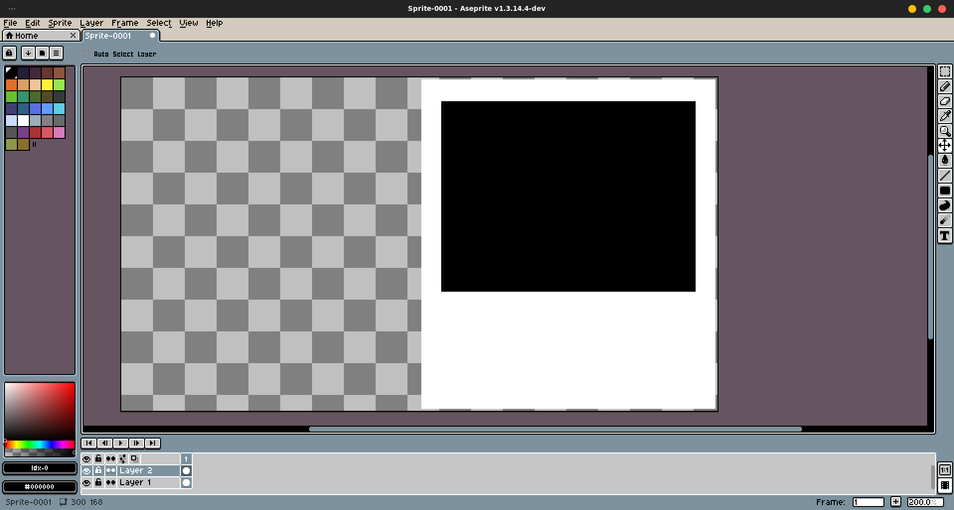
But large portion of time this session was spent making a readme header, which I imagined as a gif that would be like a demo for the usecases. I downloaded aseprite, which is actually free if you compile it yourself!
I made a scetch of the dimensions:
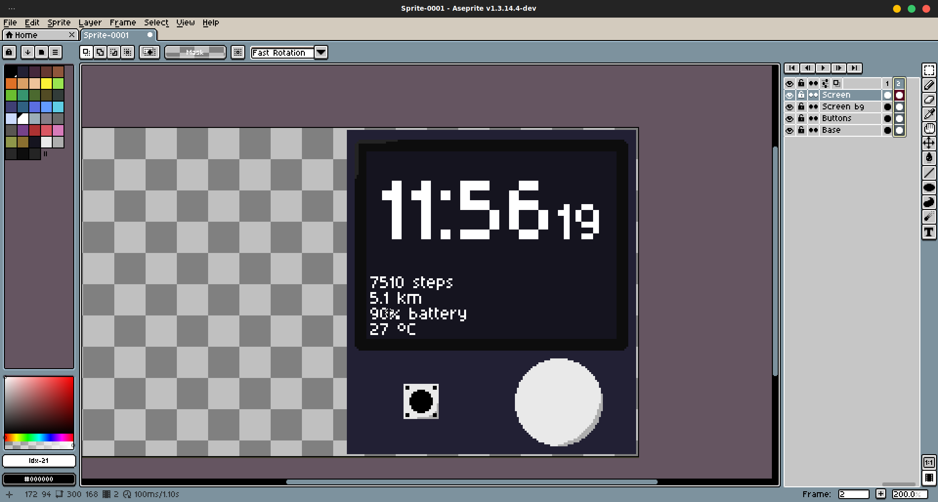
 And then continues with clock ui
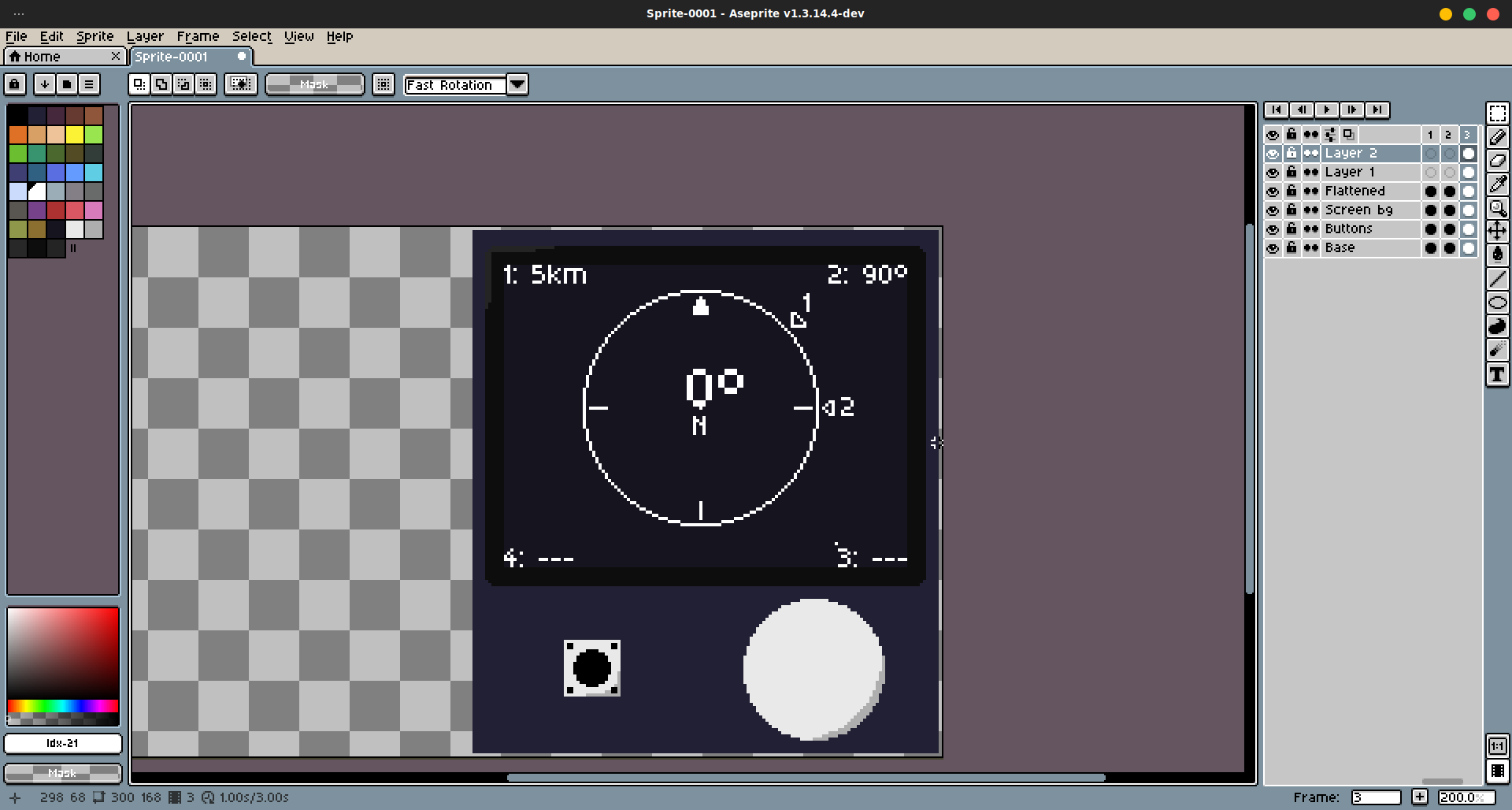
 And finally compass, which will rotate.
 And this is the result!
Time spent this session: 3h46m
July 23-24 Proper CAD
After asking in highway's slack channel, i found out that 3d models are neccesary for every project. I was hoping that because I'd apply for the lowest tier that i wouldn't have to do a case, but i was wrong. So i installed Fusion because i've felt it would have most community resources and also I've tried onshape before and didn't really like it.
The guide for hackpad 3d modelling was really useful for me, at least in the beggining. I was able to draw the first scetch, which will be floor, support for battery, support for 2nd layer and also it will define the walls.
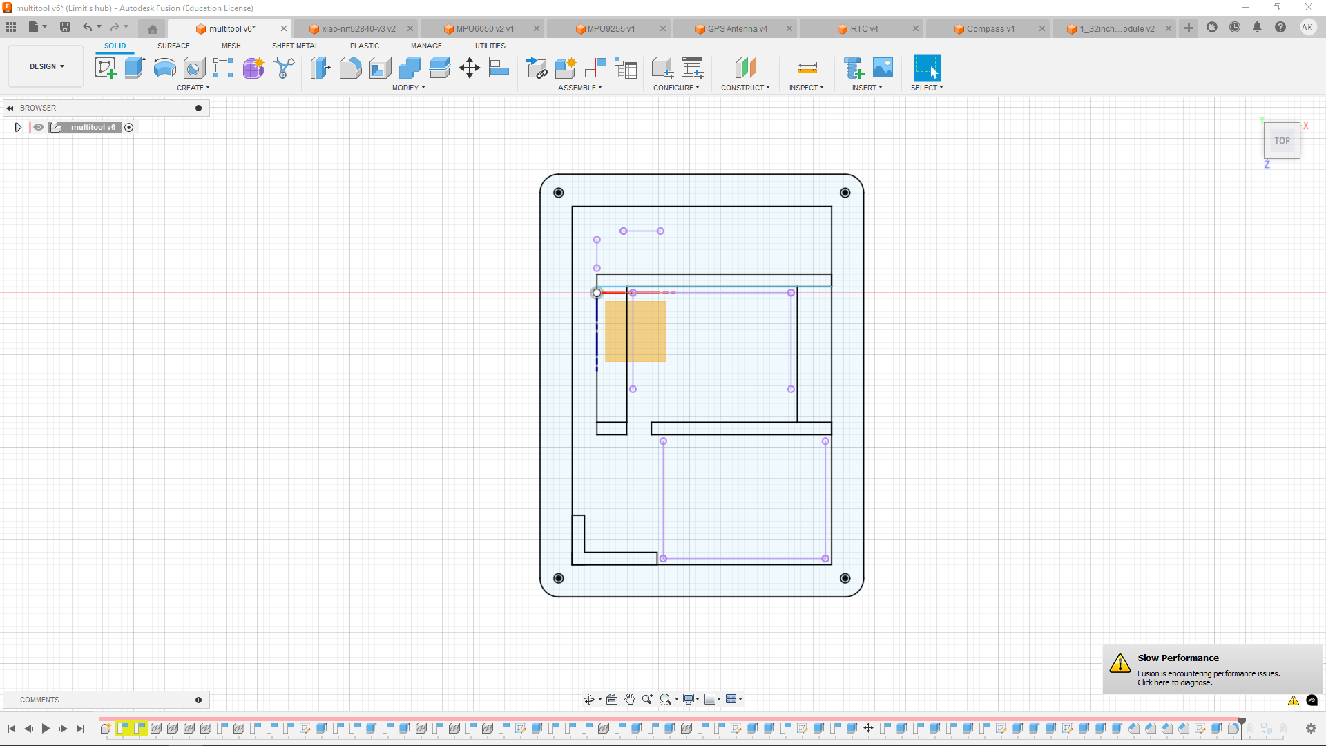
I was drawing the scretch alongside the imported components.
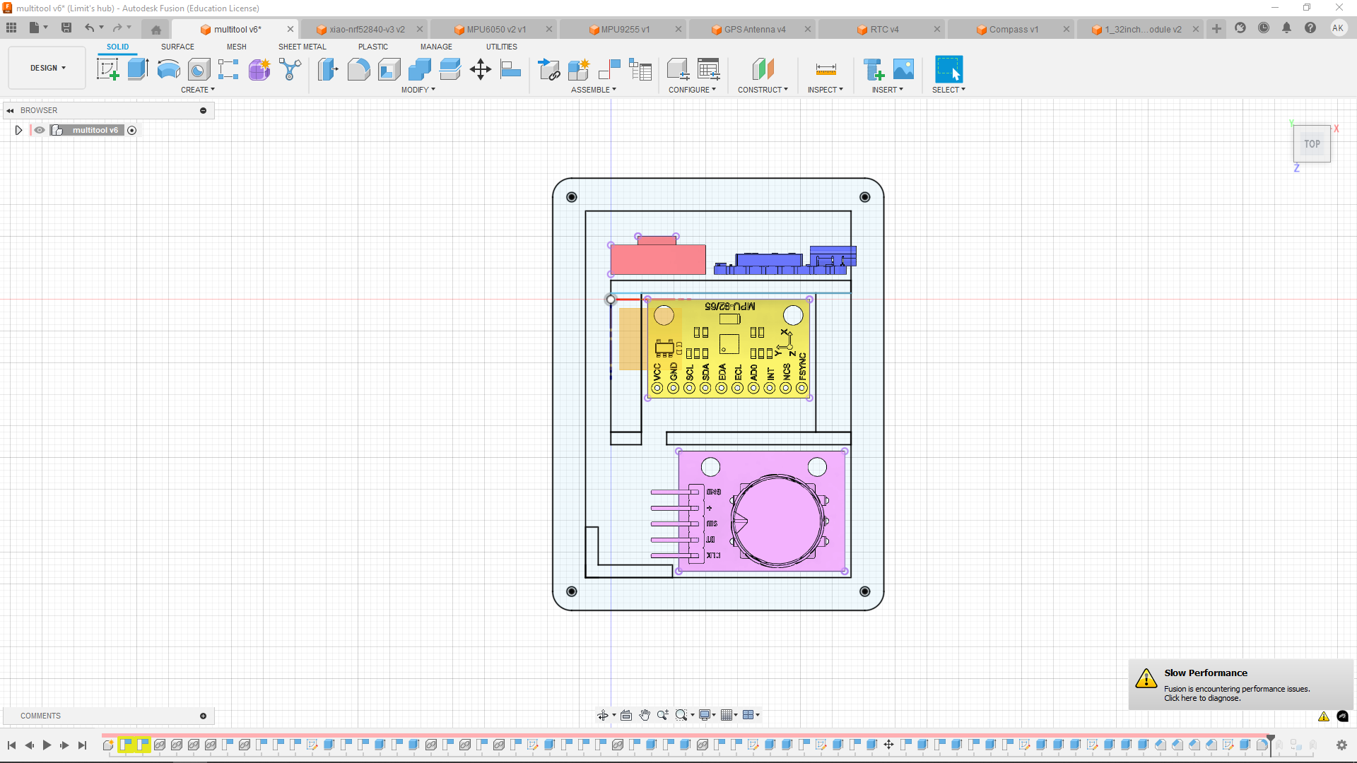
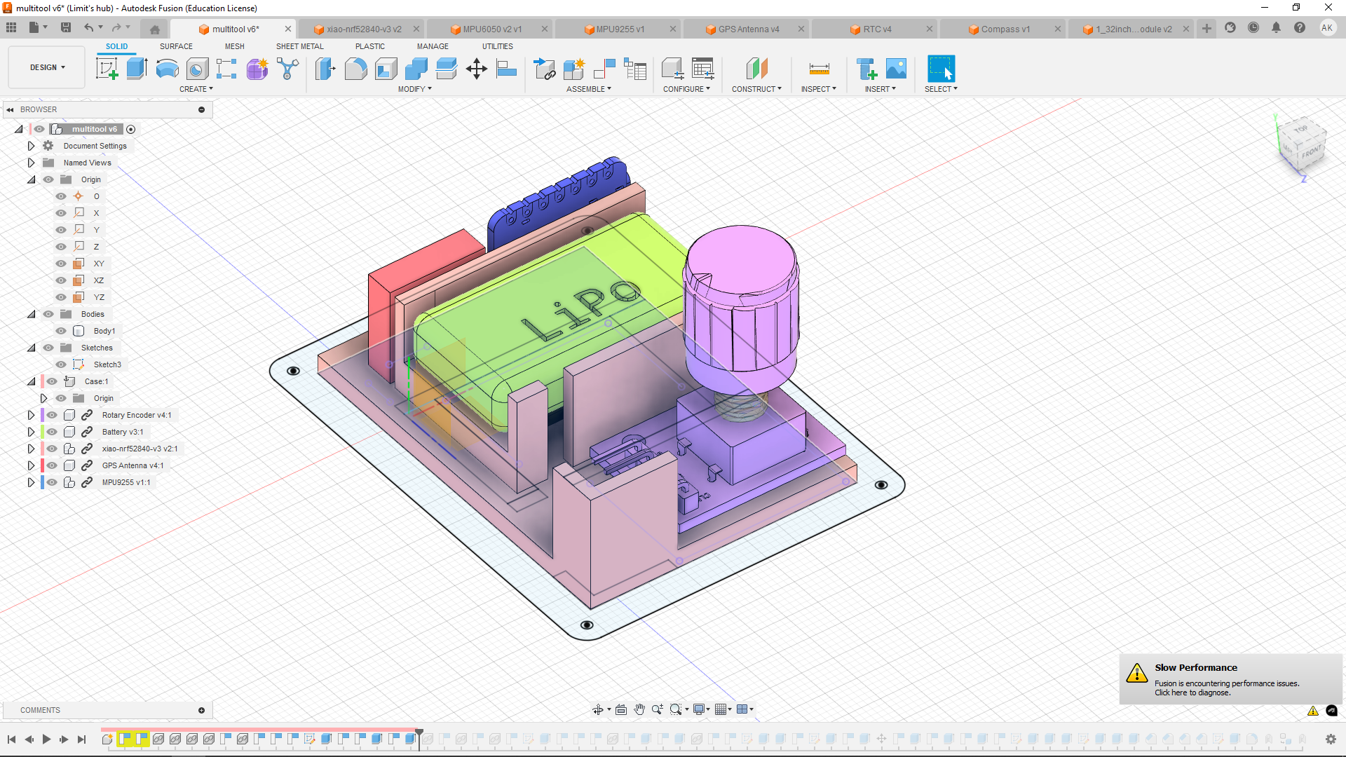
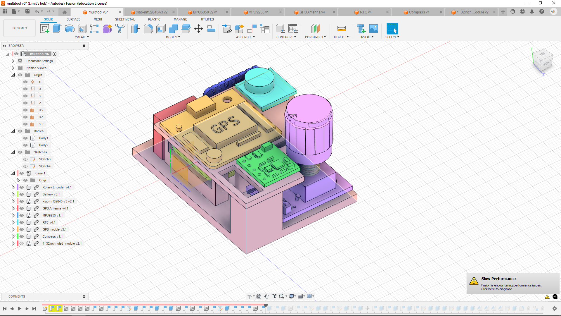
I then raised the drawed shapes to form a 3d shape. I've raised both the battery support and 2nd floor support. Then i placed the battery on top of the accelerometer, and thanks to the supports they aren't in contact with each other.
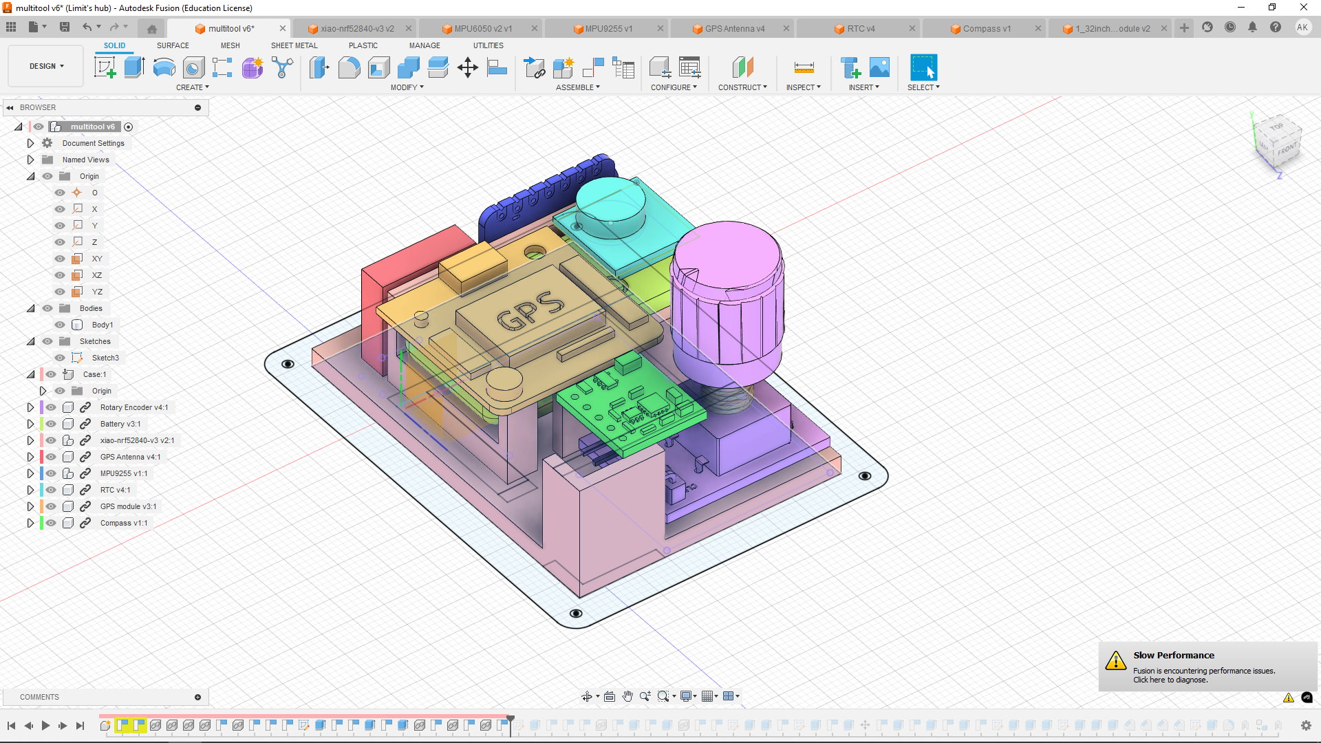
After that I placed the 3 modules that would be on the second floor, RTC, GPS and magnetometer. I placed them into the air at first, so i ccan draw scetch around them. In the scetch in the bottom left corner of the 2nd floor i made a hole for wires, which has a tunnel already made all the way to the microcontroller.
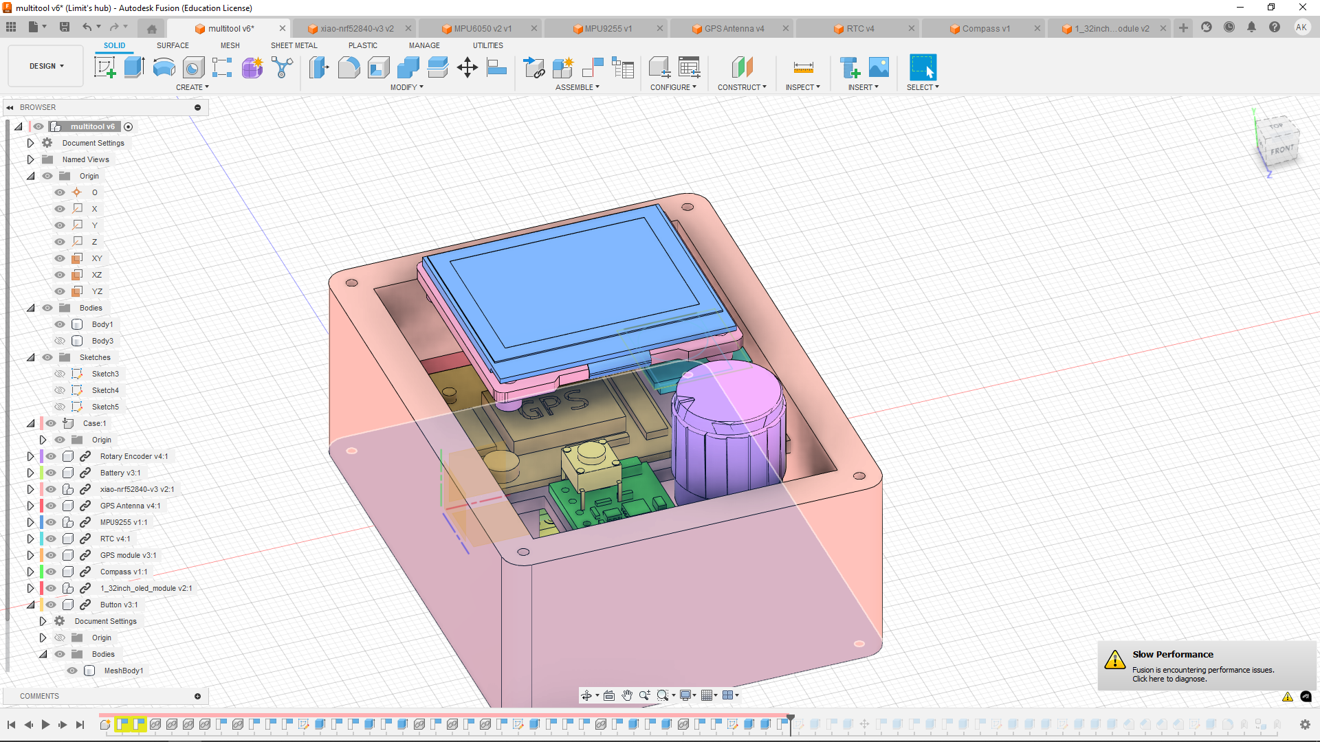
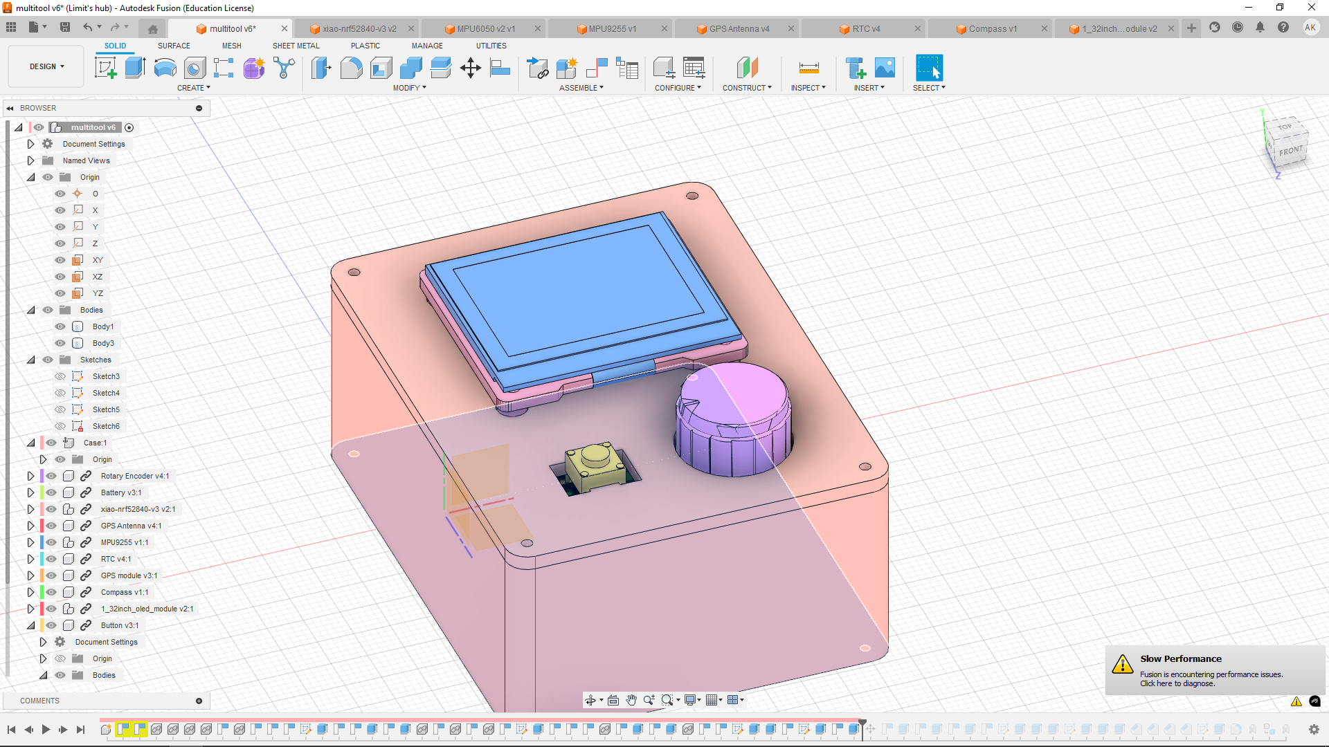
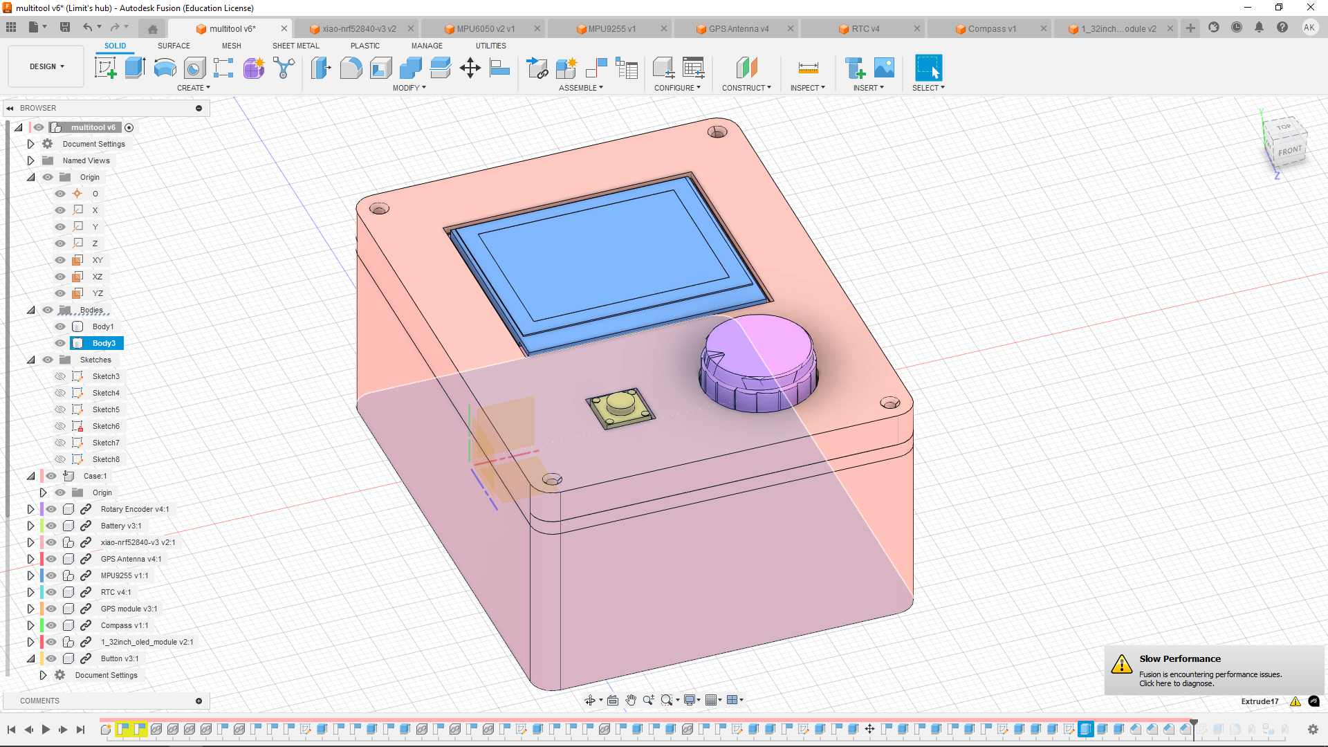
I started working on another layer, which will hold the display and push button up and it will be the first layer that mounts directly onto the walls, so it won't be glued inside like the layer before. I first centered the screen to the whole case, which I've done using the align tool. The button was also aligned, but to the top face of the knob. And then drew holes for screw on the bottom of the scetch and in the top made hole for the knob and the button, which also has a little bridge holding it.
I realized i need an another layer on top of this, to hide the screen edges and also encase the button.
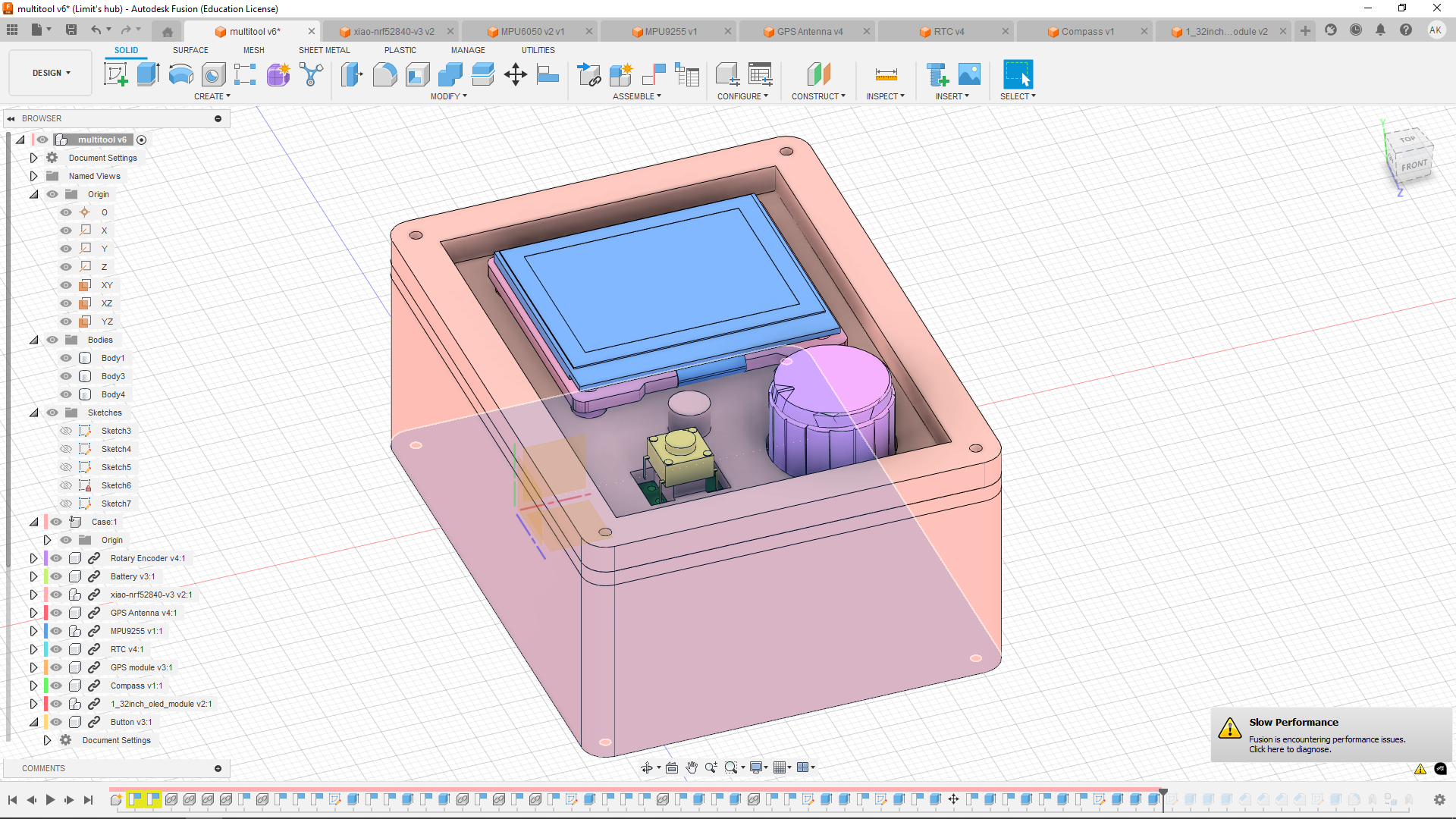
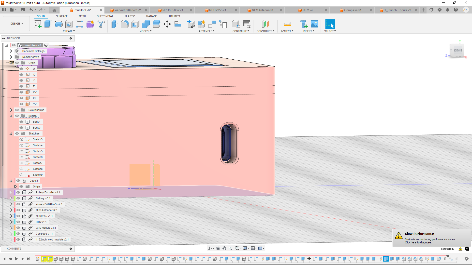
And i didn't forget to add the hole for USB-C.
 Time spent this session: 8h13m