
Boop
This is a devlog for this 3d printer im making! (im keeping this casual)
total time: 98.5 hours
Day 0 (24-25.05.25) ~15 hours
Today i did research, setup fusion, and started making a scetch for the base!
After that, i started making the polar mechanism itself, designing the gears and belt. Now if gear A (the small one) is spun, gear B spins too. On the left, seperated for now, is a part of the printbed and elemesnts allowing it to spin (atleast they will in the future).

Day 1 & 2 (27 & 29.05.2025) ~2.5 hours
With exams, i didn't have time to do much. I did do one thing though, draw out the design on my whiteboard. I also found a good extruder to use (sherpa mini), paired with the XC1 hotend and a dragon burner. I have already gotten the cads for them, and only need to assemble them within fusion. And more research on how to do the z axis. The problem with the design in the video, is that it shakes, and like a lot. To solve it, im considering adding another arm, on the other side of the cartridge. This would substantially minimalise shaking, but slightly increase the price. I think its a good trade, as the other way involves getting rid on the cantileverian design.
Day 3 (13.06.2025) ~0 hours lmao
Thank god i passed everything, finally have got time to continue this project.
Day 4 (20.06.2025) ~3 hours
I completed the whole extruder part, by using the sherpa mini with the xc1 hotend, combined with the dragon burner. Starting on the x axis, i have completed the design on paper, now i only need to bring it onto fusion. I also will be using a 2x sliding rods, and 2x lead screws for the y axis, but i will add that after i finish the x axis.

Day 5 (21.06.2025) ~5 hours
Im continuing my work on the x axis. Found and added pulleys needed for the design (6 total), added the vrail and carriage). All designed by me, its why it took soo long

Day 6 (25.06.2025) ~6 hours
Today i added a pulley at the end of the vrail (it isnt connected yet tho, im yet to do that). I also added a second pulley at the other end, it will be moving the extruder. In here, i created a part that will hold it, it fit snugggly into the vrail, with 0.1mm margin. It also will have a whole in the middle (through the whole thing, including the vrail), to slide in a blot, so the whole thing doesnt move or shake. It also has 2 ball bearings, with inside diamater of 20mm, the same as the pulley.


Day 7 (26.06.2025) ~5 hours
I added the holder for the bottom pulley, and redid the holder for the front pulley (it had 0 margin, and not it has 0.05 margin. Idk if its the gap is big enough, but its a cheap 3d printed part, so no big deal). I also did research on how exactly a mount should look, since i need one to connect my sherpa with xc1. I decided on the 4010 axial to provide general flow onto the heatsink, and a radial fan (5015) for the tip of the nozzle. I will want to make it as light as possible, but will likely need an airduct to channel the air, but since its plastic it shouldnt add much.

Day 8 (26-27.06.2025) ~6 hours
I created the mount, connecting the 4010 fan, with the sherpa and hotend. The blank space opposite of the fan, will be filled by a material mesh i have at home. It currently doesnt have a mount, since i plan to add another part, made with cnc, or bought online, where i will insert the 20mm diamater rod, and then screw it to the mount.


Day 9 (03.06.2025) ~5 hours
I made a mount, however its horrible. takes up too much space.

Now it looks like this! It has a space to screw it in, on its 4 corners, and a screw to fit into the rod, which is also custom made!

I also atlast connected it to the rod, and the x axis is completed!

Day 10 (06.06.2025) ~8 hours
Now i added a belt and created new pulleys for the x axis!
 I has to redo the belt, bc i needed to increase the length of the xaxis rail by 100mm. I also added 2 plates on either side, to hold all the pulleys, and positioned the nut blocks, made screw holes for it. Also put the nema17 motors, but theyre not yet mounted.

Day 11 (07.07.2025) ~4 hours
Today i added holders for both sides of the xaxis, which hold everything together. And put the nema17 stepper motors for 2 pulleys, and 2 lead screwws they'll be powering. I have decided on putting both on one side, since putting 1 per side would make it extremely akward to design, and would unevenly distribute weight in a way thats harder to fix (now, i can just put weights/needed electronics in the other side). The heavier side also has a linear rail.


Day 12 (08.07.2025) ~4 hours
Now i added holders for the 3 stepper motors on the bottom, and added a holder for thr rail. I also started the protectors for the screws, and recreated a pillow bearing. Its still a wip, but i need only to add the top, reinforce it, and connect it to the linear rail holder.


Day 13/14 (09.07.2025 - 21.07.2025) ~10 hours
This 2 weeks i added classic rail, to stabilise the build, as well as adding 3d-printable supports for it. The rail one, is connected to the screw one, and those are connected to the nema17 holder at the base, and to the other linear screw holder at the top.
 And i also upgraded the holders for the 2 nema17 i have at the bottom, now its 1 3dprintable part for both motors, which o directly screwed to the base in 8 places, connected to the linear screw and classic rail holders, via screws, and is held in place by an additional metal plate, at its top. I also added the whole base and space in the middle for parts such as: control board, psu, stepper drivers, cable managment, etc.
Day 15 (25.07.2025) ~8 hours
A lot of stuff done today!
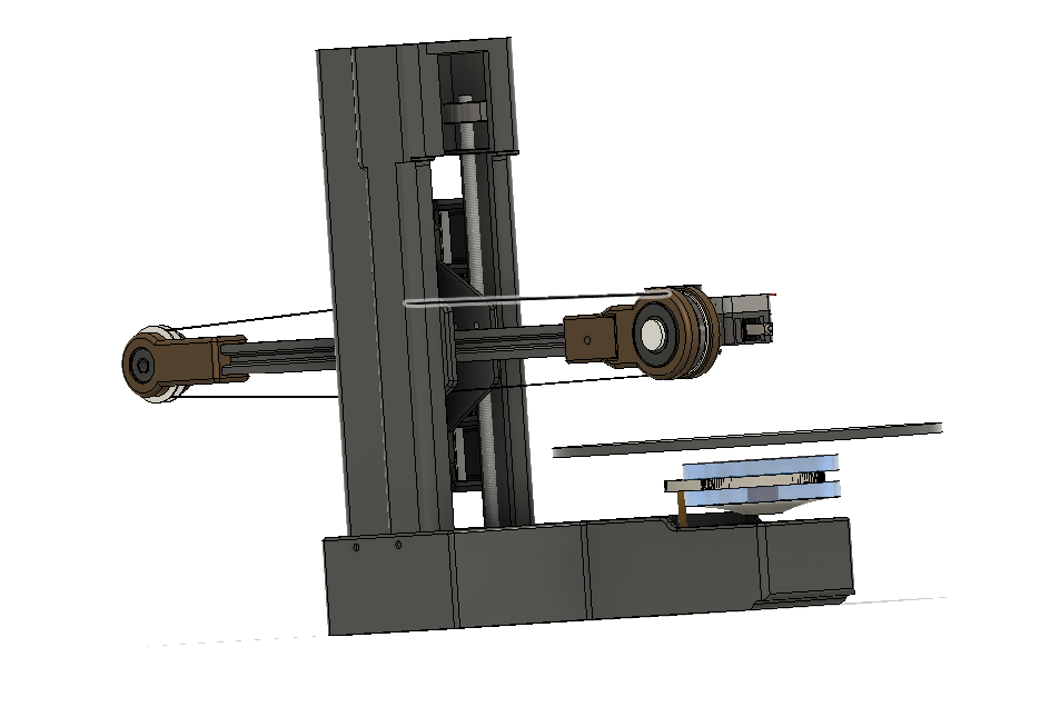
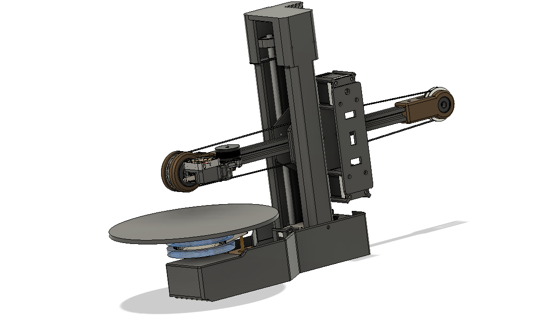
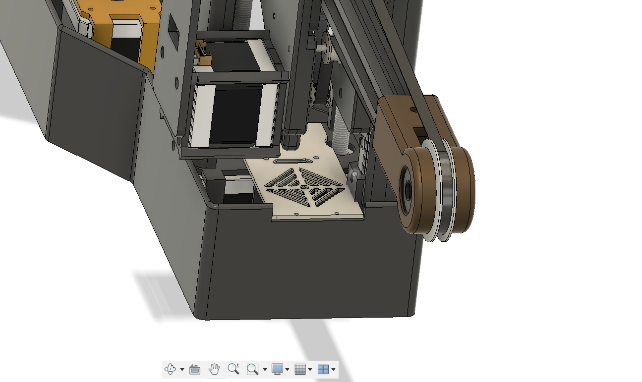
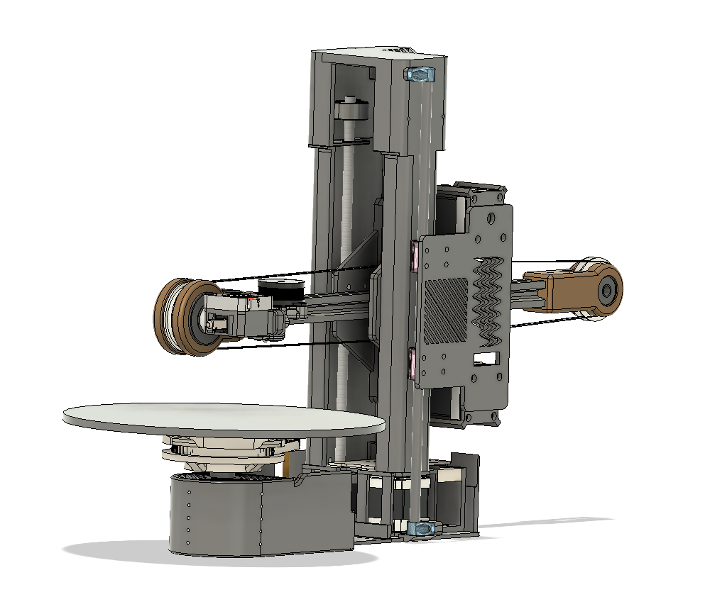
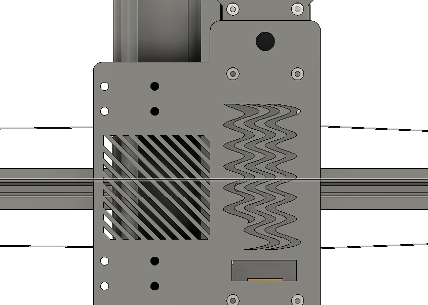
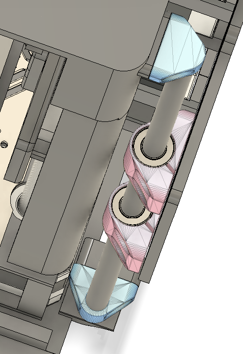
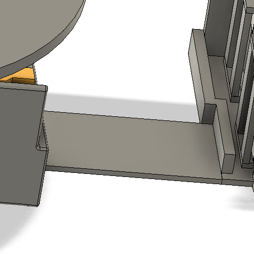
it looks like this now! I added a sliding rod on the opposite side if the x axis, relative to the classic rail. Now, it will definitely be stable, so to not make it ugly, i added a few cutouts on the plate! Said plate is connected to the sliding rod, via 2 adapters and LM8uu bearings.
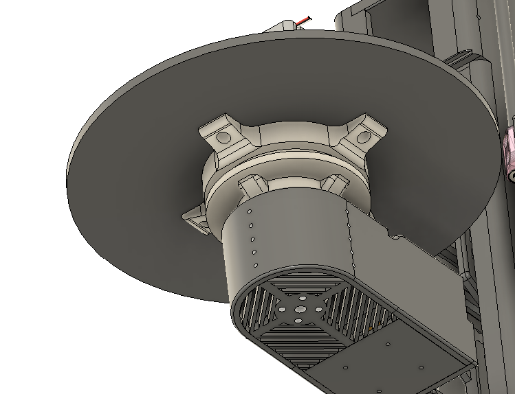
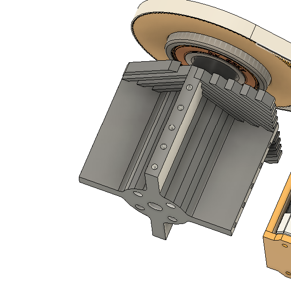
On the other side, i completely revamped the printbet, now its more stable, slimmer, and cheaper. The gear holding the belt, is connected to the printbed. It uses 1 bearing with 29mm inside radius, which is used to insert a static rod from the base. The base was also modernised.
Day 16 (30-31.07.2025) ~8 hours
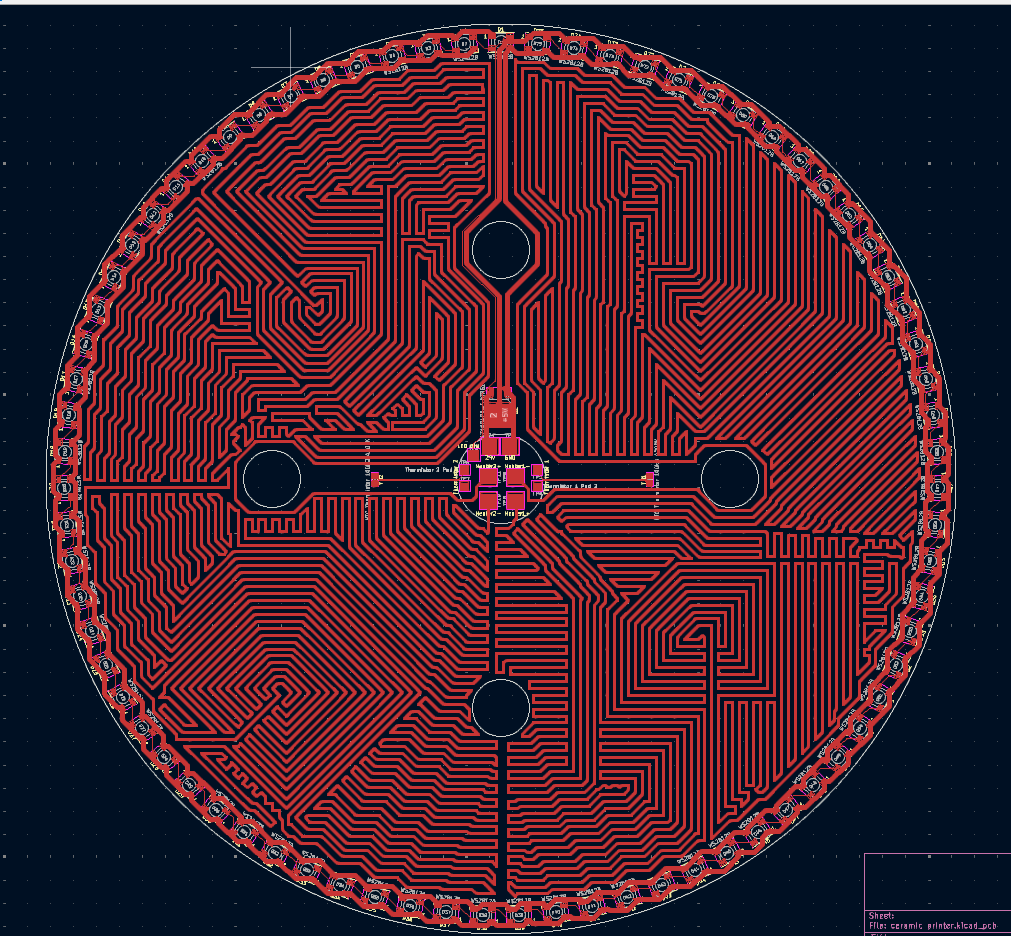
The first part of making this (the schematic and wiring leds) was a pain, but wiring the heating pads was weirdly satisfying, like the slime videos xd.
The pixels are for pure decorational purposes, and the wiring was made to keep almost all of the printbed evenly heated, even if its asymetrical.
Day 17 (31.07.2025 the evening, not 3am like before :3) ~9 hours
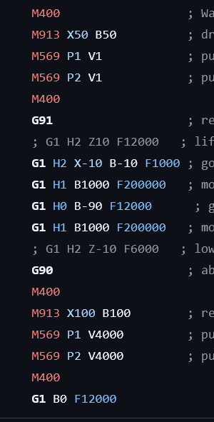
Turns out making reprap firmware at the last possible day wasn't the best idea, but thankfully i did my research and ytvideo watching earlier, so it went rather quick.
Parts:
| Part | Qty | total | link |
|---|---|---|---|
| sherpa mini | 1 | 34 | Ali |
| vslot rail | 2 | 16 | Ali |
| nema17+screw | 1 | 50 | Ali |
| nema17 | 3 | 44 | Ali |
| skr3+drivers | 1 | 77 | Ali |
| lrs-350-24 | 1 | 35 | Ali |
| pillow-bearing | 2 | 12 | Ali |
| pulley | 2 | 3 | Ali |
| pulley no-teeth | 4 | 12 | Ali |
| back-pulley-xaxis | 1 | 2 | Ali |
| big-xaxis-pulley | 1 | 5 | Ali |
| bearing-uni | 4 | 5 | Ali |
| gantry_vslot | 2 | 18 | Ali |
| 4010 fan | 1 | 4 | Ali |
| sliding rod | 1 | 23 | ali |
| lm8uu bearing | 2 | 3 | ali |
| m4 screws+nuts | 36 | 8 | local_shop |
| m3 screws+nuts | 25 | 8 | local_shop |
| m2 wcrews+nutss | 4 | 1 | local_shop |
| m2.5 screw | 2 | 1 | local_shop |
| m5 screws+nuts | 35 | 4 | local_shop |
| m8 screws+nuts | 5 | 4 | local_shop |
| B57560G1104F000 thermistor | 2 | 8 | mouser |
| leds4printbed | 75 | 15 | piekarz🔥 |
| gt2 belt | 1 | 8 | Ali |
| nutblock | 2 | 6 | Ali |
| xc1 hotend | 1 | 2 | Ali |
| jumper cables (m2m & f2f & m2f) | 40 each | 8 | Botland note: after customs aliexpress is actually more expensive + m2m and f2f connectors cost the same - ~2.5$) |
| endstop switches | 3 | 4 | |
| pcb | 1 | 50 | jlcpcb |