Delorean
Journal (total time spent: 20 hours)
Thursday, June 5 2025 (~3 hours spent)
I've been deciding between a couple projects for some time, and finally decided to commit to a nixie tube clock. I talked to Alex Park a ton about his clock
that he made in january, and he gave me a ton of advice. I searched around for other clocks people have made and have boiled my BOM to 6 items:
- x6 IN-12 nixie tubes
- x6 K155ID1 controller chips
- x1 6V to 170V boost controller power supply
- x1 Raspberry pi pico W
- x4 AA Batteries (+ 1 case)
- x1 PCB and shipping
This isn't counting some resistors and capacitors I might need, but I'll research those later. The K1551D1 is a chip made for controlling nixie tubes (and alex used it so I'm copying him). I chose the pico W because it has RTC, a bunch of GPIO pins (you need 25 for a 6-digit nixie clock), and it's WiFi enabled. The total is around $70, which is completely doable. I'm excited. I'm kinda afraid of shocking myself, but it'll probably be okay.
Friday, June 6 2025 (6 hours spent)
I had to find a boost converter that could be bought in bulk and tried to find
KiCAD footprints (I'd already resigned to making the symbols myself) but none of them are named???? Like not a single boost converter I found that can get up to the 170V needed
for 6 IN-12 tubes have names. No part number, just 3V-6V to 170V Boost Converter Nixie Power Supply 6pcs 12pcs Very Cheap Awesome Good Quality
. So, yeah great.

Then, I made the project in KiCAD
DeLorean, there's probably a wittier name but whatever
and got to work making the boost converter, K155ID1, and IN-12 nixie tube symbols since apparently, even though tons of people make these clocks and they sell for like $300 on amazon, I'm too blind to find a good one on the internet. And it doesn't help that the datasheets for these look like they haven't been updated since the Russians made these things back in the cold war.
 I have to order one of the boost controllers so I can make a footprint for it,
again, it doesn't have a name and kinda seems like it doesn't exist outside of aliexpress and ebay, am I doing something wrong?
but it won't arrive until I'm in vermont in 2 weeks, so I'll have to wait till then to make it.
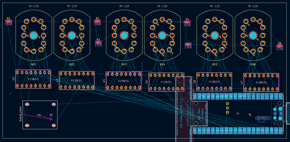
I laid out and wired the rest of the schematic

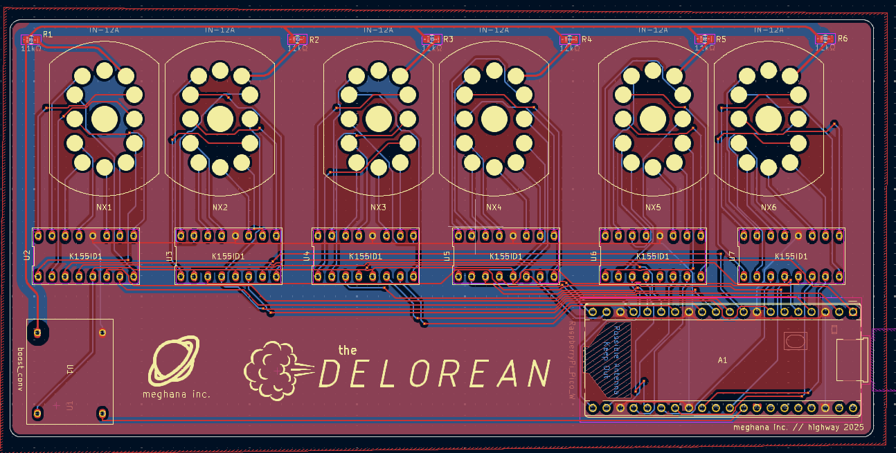
And this is the first version of the PCB
The boost converter footprint is just a placeholder for now, and I have to route the whole thing. Alex's told me that you should make the area above the K155ID1s high voltage zones and the area below everything else. So I'll have to do that. Awesome.
Saturday June 7, 2025 (2 hours spent)
Here's a tentative BOM | Item | Qty | Cost/item | | ---- | --- | ---- | | IN-12 nixie tubes | 6 | $5 | | K155ID1 controller chip | 6 | $1 | | 5V to 170V boost converter | 1 | $10 | | Raspberry Pi Pico W | 1 | $8 | | DIP-16 chip connecter | 6 | $0.25 | | Custom PCB from JLCPCB | 1 | ~$10 | | Battery case | 1 | need to find | | AA batteries | 4 | need to find | | USB Isolator | 1 | need to find | | Total | | ~$80 |
Monday, June 9 2025 (2 hours spent)
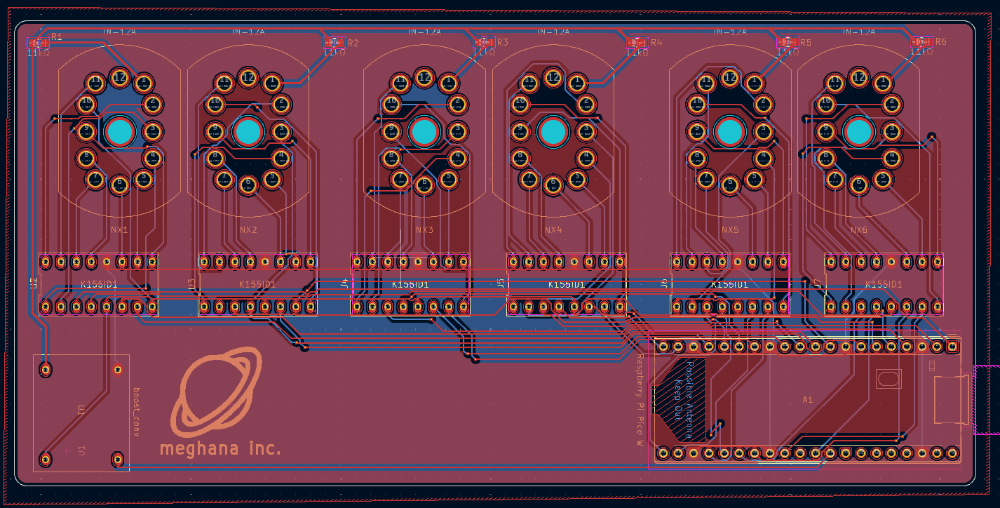
I routed the PCB today, and then found that my pico W footprint was SMD so I changed it and then routed it again (awesome).
Note to self: routing is hell.
I actually used filled zones for the first time: the gnd should reduce noise and help with cooling, which is super sick. This isn't the final PCB obviously because I have to actually make the boost converter footprint and add some more silkscreen stuff, but it's looking pretty good. I'll start CADing the case in Inventor soon, so that should be fun. The hackatime kicad extension is being weird so it's not logging all of my time but its okay because we do it for the grind (call me dr seuss).
Tuesday, June 10 2025 (2 hours spent)
Getting back into CADing things again, and since I wasn't a fan of the nixie tube model I downloaded (KiCAD's renders doesn't have opacity so they just look like solid blocks) I opened up inventor and started messing with it. Then, it didn't save all my appearance changes so I just deleted the outer shell and gave up.

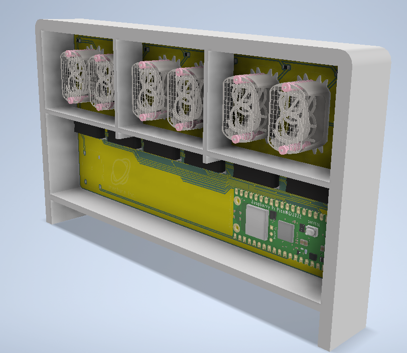
Started the case today, it was pretty fun once I got into a rhythm
then I had the depressing realization that I will probably spend 30% of my life in CAD. Anyway. Here it is!
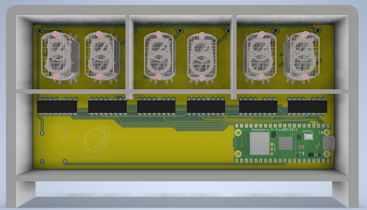
Pretty cool right?
Wednesday, June 11 2025 (3 hours spent)
I put fillets on the high voltage traces on the PCB (half for fun and half cause apparently it helps isolation ??) and updated the BOM. Batteries are a bad way to go, you'll need to replace them often and it's just a pain.
BOM
| Item | Qty | Cost/item | Total Cost |
|---|---|---|---|
| IN-12 nixie tubes | 6 | $5.08 | $30.50 |
| K155ID1 controller chip | 6 | $1 | $6 |
| 5V to 170V boost converter | 1 | 10.50 | $10.50 |
| Raspberry Pi Pico W | 1 | $7.65 | $7.65 |
| DIP-16 chip connecter | 6 | $0.25 | $1.50 |
| Custom PCB from JLCPCB | 1 | ~$10 | ~$10 |
| USB Isolator | 1 | $9.99 | $9.99 |
| USB A to C | 1 | $1.29 | $1.29 |
| Estimated shipping | $15 | ||
| Total | ~$95 |
actual BOM here
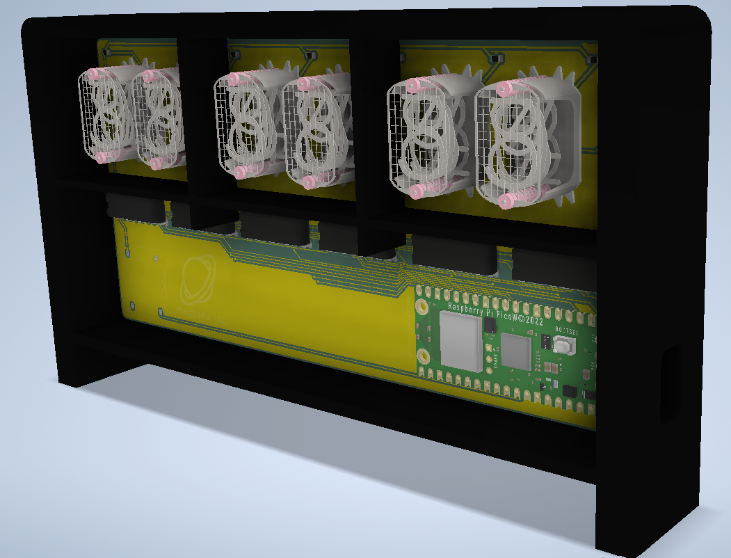
I got some more work on the case done, so that was nice. Still trying to come up with ideas on how to make it look more cool. Also, I wanna make another case that can be used if the clock is horizontal.
Thursday June 12, 2025 (2 hours spent)
Coding the firmware today was fun. Obviously I can't test it and see if it works (which is probably why it was so fun).
it should workfamous last words
I wanted to use NIST for syncing time because my math teacher talked about it like it was some sacred, profound institution and it would be cool, but apparently Network Time Protocol is better because it searches for a server that's closest to you. Also, today I learned that digitalWrite() takes booleans, very cool.
Friday June 13, 2025 (15 minutes spent)
Added some silkscreen stuff and increased clearance for the 170V traces. Pretty cool stuff.