
Starkit
A thrust vector controlled electric model rocket designed for propulsive landings
Total time spent: 70h 45min
May 22: Initial ideas and goal of the project
I always like to begin engineering projects by setting a goal. For this project, my goal is the following:
To learn and have fun by building an electric model rocket capable of lifting off, hovering and landing propulsively
I want to build a fully reusable vehicle capable of landing propulsively through thrust vector control. If the rocket is capable of performing a 1 meter hop and hover for 30 seconds, I will consider it a success.
Based on my vision for this project, I've set some design requirements. This way, I will try to find the most efficient and cost-effective way possible of creating something that I'll be happy with:
Design requirements
These are the absolute musts that a design should have:
- The rocket is powered by electric propulsion for cheap and safe flights and fast turnarounds
- The rocket is fully reusable and uses thrust vectoring to lift off, hover and land propulsively
- The rocket can perform a 1 meter hop and hover for 30 seconds
The rocket is modular
- Components are easily accessible and replaceable
- The rocket is designed for a future launchpad integration
If I achieve reliable landings, I might try to build a launchpad to launch and catch the rocket from. The rocket should be modular and be designed with this in mind. - The rocket has got detachable or deployable landing legs and attachable catch pins - The pad should be able to hold the rocket until full throttle is reached
Dream goals
These are not essential but they'd be cool to have:
- The rocket can perform a 10 meter hop
- The rocket can hover for a minute
- The rocket looks as cool as possible
Initial ideas and concepts of possible designs
Time spent: 1h 15min
May 24 Log 1: Research on propulsion systems
I've decided to choose a propulsion system first and then work around that. Some options I think would fit this project are:
- Single EDF (Electric Ducted Fan)
- Single propeller
- Counter-rotating propellers
- Ducting a propeller(s) myself
The main things I've learnt today are:
- Ducting a propeller can increase efficiency and thrust.
- EDFs take advantage of this. An added benefit is that they often have stator vanes that minimize the torque produced by spinning the propeller.
- A larger propeller is usually more efficient and provides more thrust. A larger propeller could match the thrust of a smaller EDF while being less expensive, however the torque and gyroscopic effects become greater the more you scale the propeller.
- If I use a single propeller I probably wouldn't want to duct it myself as it could actually decrease the performance (EDFs are propeller and duct combinations specifically made to work together).
I've discarded ducting a propeller myself. However, I still have to make more research to figure out what the best option is. If I manage to overcome the gyroscopic effects, a single propeller would be a nice option over an EDF, as it would be less expensive. Counter-rotating propellers would also be a good option as they cancel their torque, but I still have to research if the thrust of two propellers in series is just the sum of their individual thrust.
Time spent: 2h 30min
May 24 Log 2: Research on counter-rotating propellers
The reasons I would choose counter-rotating propellers over a single propeller are:
- They cancel their torque, which means that they don't apply any rotational force to the vehicle and you don't have to worry about gyroscopic effects.
- You have some control authority in the roll axis. If the rocket gains angular speed, you can correct it by adjusting the throttle of each individual motor. This also allows me to only use 2 servos for TVC, as you only need to correct 2 axis.
The Ikarus model rocket had an issue where whenever it wanted to apply a torque through TVC, it had to apply a perpendicular torque as well due to the gyroscopic effects of a single propeller. In the Ikarus II rocket this problem was solved by using counter-rotating EDFs.
Placing the propellers one after the other would decrease thrust and efficiency. However, if I keep the propellers spaced and use airflow straighteners for feeding the second propeller cleaner air, this could be mitigated.
Test on the efficiency of normal, overlapping and coaxial propellers. Coaxial propellers are about 80% of the efficiency at a low spacing. Source: https://www.youtube.com/watch?v=tFJyE3Uns3o
If I want to get as much thrust as possible in this configuration, I should use a higher pitch in the rear propeller. However, I don't think this is a good idea as there aren't many high pitch propeller options or test data, and using different propellers might cause them to rotate at different speeds, which could cause a torque in the vehicle.
Test showing the thrust of different propeller spacings and rear propeller pitch difference. Source: https://www.icas.org/icasarchive/ICAS2014/data/papers/20140072paper.pdf According to https://drones.stackexchange.com/questions/1209/do-propellers-layered-on-top-of-each-other-have-twice-the-thrust-of-one-propelle, you can get almost the full thrust if you increase the pitch of the rear propeller._
I'll have to do more research to figure this out, nonetheless I think counter-rotating propellers are a really good option.
Time spent: 1h 30min
May 25: Deciding on counter-rotating propellers
After some research I’ve decided that using two identical counter-rotating motors and propellers is the best option. You avoid torque and gyroscopic effects that you would have with a single propeller or EDF, and you still can get their full efficiency by placing them side by side. However, I'll have to see if even with the structural weight that would add placing the propellers side by side, this configuration would outperform placing the propellers one after the other.
https://www.youtube.com/watch?v=VsyFejn40Ss
This video shows a vehicle with a similar configuration to what I was thinking. However, TVC roll control is later added because adjusting the throttle of each motor is not enough and causes the rocket to lose thrust.
I could test the thrust of the motors at different throttle levels to try and avoid this, but either way I think adding TVC roll control would be better. In the future the rocket could need precise roll control if I attempt to build a catch tower.
Time spent: 1h
May 27 Log 1: Deciding a motor configuration
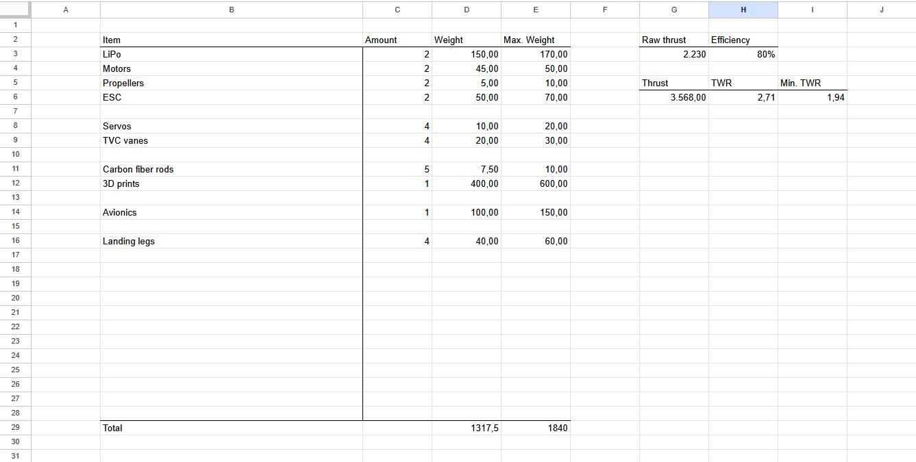
I've made a spreadsheet for calculating the thrust to weight ratio (TWR) of a coaxial and a side by side configuration.
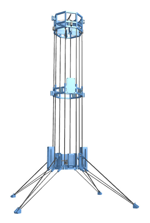
For the coaxial configuration, I'm picturing a cylindrical structure with a propeller at the top and another at the bottom. For the side by side configuration, I'm thinking of 2 of such structures next to each other, with one propeller each. Note that this isn't necessarily the only way of placing the propellers one next to the other, but I want to keep a shape that can integrate nicely with a launch mount and a catch tower.
For the calculations I've used a carbon fiber rod structure, 4 TVC vanes and 2 Emax ECO II 2807 motors with 7" propellers. I will have to research more in depth if these options are the best for the project, but so far the coaxial configuration has a better TWR.
There are many variables that I won't know until I pick all the parts and design the 3D models. The calculations will get more accurate as I do so, but for now I will be designing the rocket for a coaxial configuration.
Time spent: 1h
May 27 Log 2: Choosing a TVC method
I had figured out previously that I need TVC roll control and I can't just rely on throttling the motors at different speeds. Because of this the only viable options I have are using 3 or 4 TVC vanes.
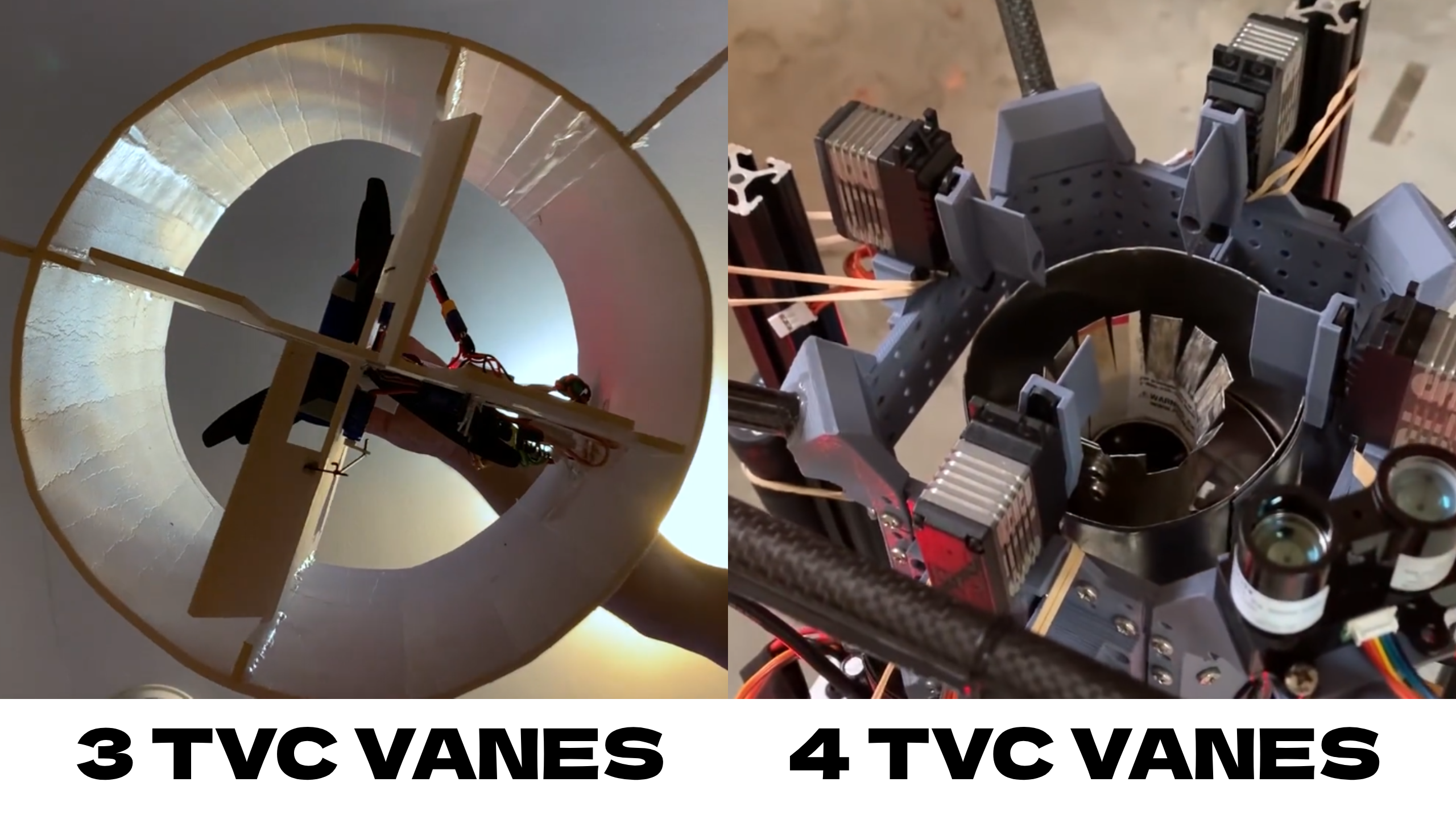
Using 3 vanes would probably be slightly cheaper. Although it would probably be fine with 3, I've decided to go with 4. The reasons are:
- 4 vanes allow me to keep all axis identical, which simplifies tuning
- 4 vanes double the control authority in the roll axis, which improves stability
- A 3 vane system needs for one vane to be longer. A longer vane would probably need hinges or supports, adding complexity.
- There are very few examples of 3 vane systems, and I haven't found any for the thrust that I'm aiming for. This makes it harder to choose servos with the right amount of torque.
- I want to keep control over the length of the vanes for balancing control authority and airflow obstruction. This is harder with a 3 vane system, as one vane has to go all across.
I don't think using 4 vanes would mean any significant cost increase, but they are simpler, they provide more control and I have more design references, so I’ve chosen to go with that.
Time spent: 1h 30min
May 28: Structure and general layout
For TVC to work properly you need the thrust vector to be far away from the center of gravity (COG). You want to place all the weight at the top and TVC the bottom motor or the other way around.
A lower COG is better for stability in landings. This means I would want to place all the weight at the bottom and use TVC in the upper motor. For this, I would need a structure without walls for the air to get out. Plus, as I had figured out earlier, I probably don't want the structure to act as a duct as it can decrease performance.
My first thought was using carbon fiber rods, which I've seen being used in similar projects. After researching some other options like balsa wood, I've come to the conclusion that carbon fiber is indeed the best option. It has a much better strength to weight ratio than others, and even though it would likely need stiffeners because it can flex, what I care about is that they provide strength with the minimum amount of volume so that they don't obstruct the airflow much.
Time spent: 1h 15min
May 29: Research on landing legs
In the future I might build a launchpad to launch and catch the rocket from, which means I would need landing legs that are either deployable or detachable so that they don't interfere with the launch mount.
I think deployable legs would be a better option. They would allow me to test the launch mount before trying to catch the rocket, and they could even allow me to abort a catch if any readings are off. Deployable legs are also much cooler and a nice challenge.
After looking at some other projects I've come up with a design that would be reliable and cheap and easy to implement.
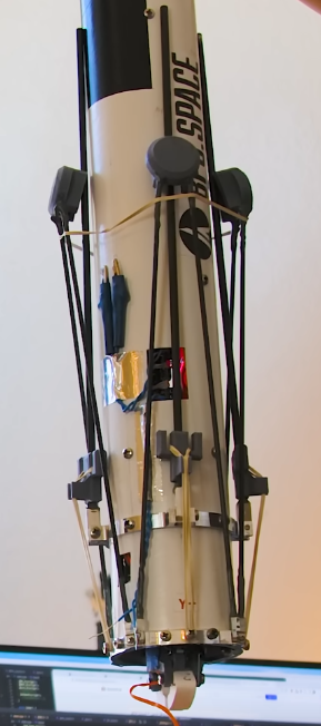
Landing legs of the Scout F rocket by BPS.space
Similar to the image, landing legs in my rocket would have 2 carbon fiber struts with a 3D print at the top. A single strut would be pulled by a tension spring (a rubber band in the image) and would snap into the 3D print when deployed, locking the leg in place. Landing legs would be held in place with servos before deployment.
I will go with 4 landing legs. It's what I've seen being done the most and I think it's a nice spot between stability and weight.
Time spent: 1h 15min
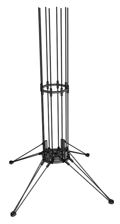
May 30: Starting the CAD design
Now that I know the general design and layout of the rocket, I've begun designing it in CAD. I don't know the parts that I'm going to use yet, but this model will help me refine my calculations. I'm designing for a 7" build, but if after making the CAD model and picking the parts I realize I have enough weight margin to scale down the motors or the whole vehicle, I will do that.
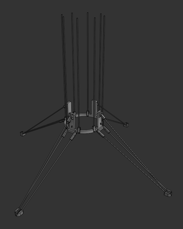
I made a new Onshape document and began designing the base of the vehicle. I've almost finished making the landing legs. Tomorrow I plan on adding the bottom motor mount and rails for integration with the launch mount.
Time spent: 4h 30min
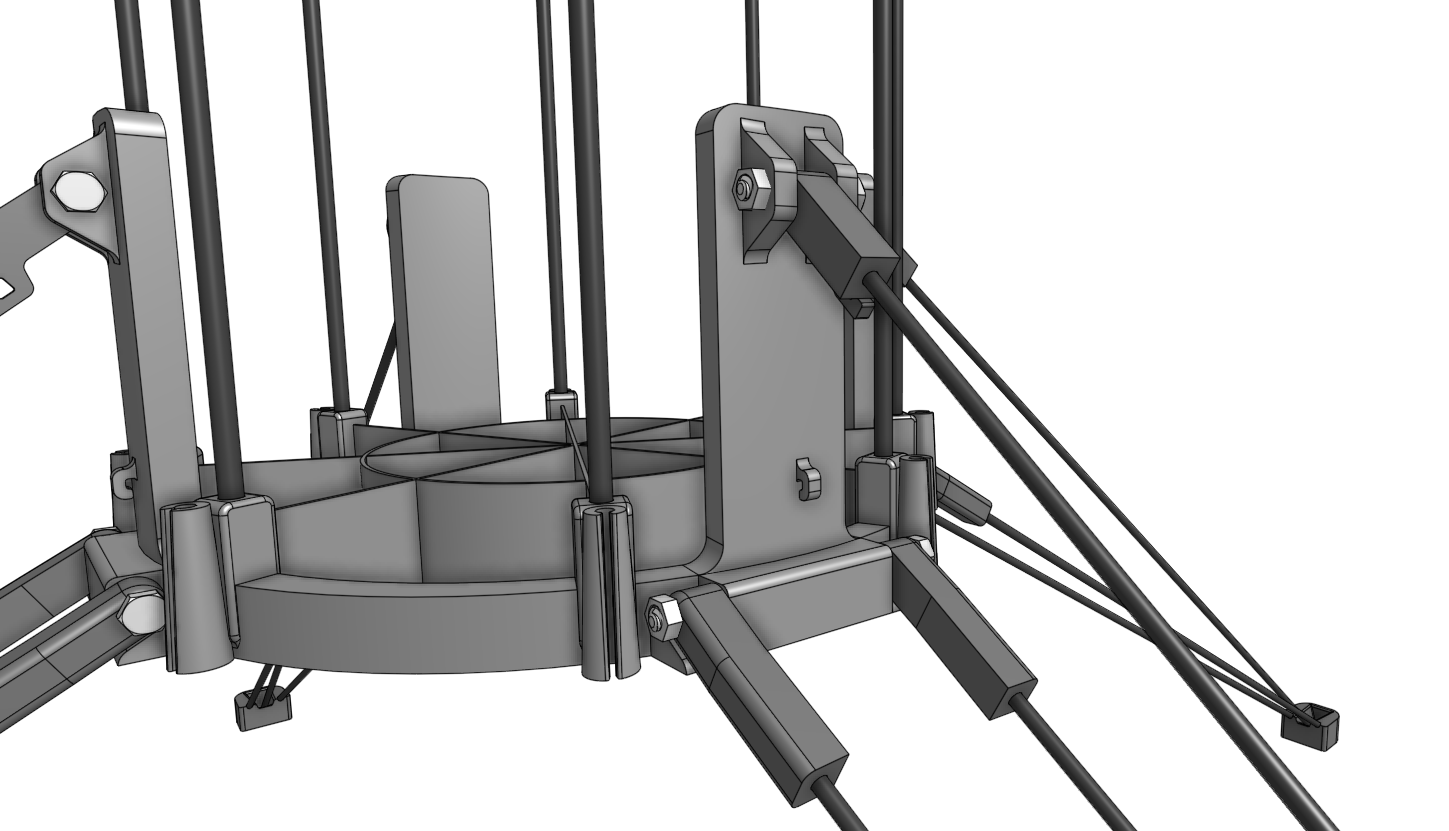
May 31: Landing legs are finished
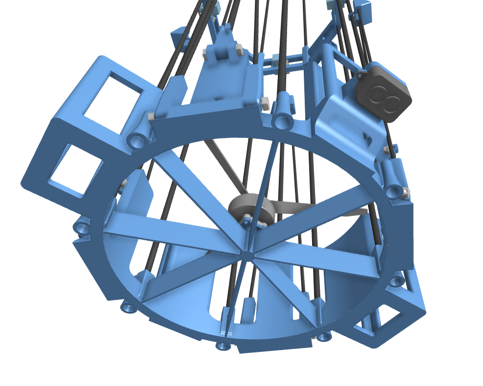
Today I've finished making the landing legs. I've added stoppers and bolts that will allow the parts to rotate into place.
I've also added the struts that will hold the bottom motor. These double as airflow straighteners, which probably isn't necessary. However I'm doing that on the top motor for feeding the bottom motor cleaner air, and I prefer to do it in both to ensure both motors behave the same and no torque is created.
Finally, I've begun making the part that will join the bottom and top rods of the main structure. This allows me to buy shorter rods which I've seen are the cheapest option, and this also makes the rods flex less. This part will hold the servos that hold the landing legs in place too.
Time spent: 4h
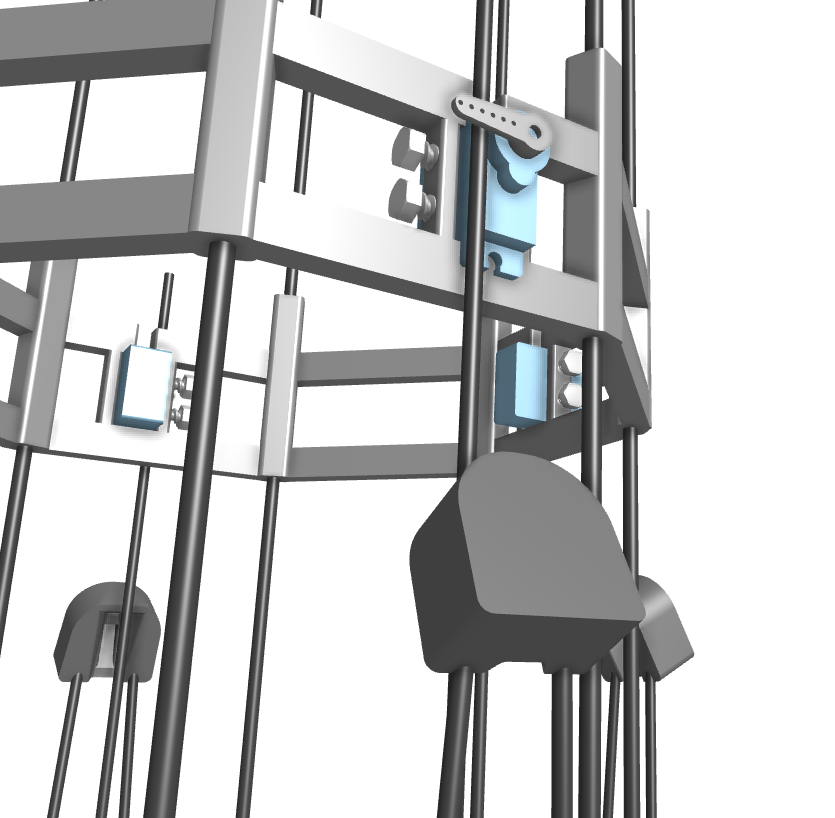
June 1: Adding servo attachments
I didn't have a lot of time today but I've figured out how to attach the servos for deploying the legs to the 3D printed part. The servos snap into some slots and are then secured with two bolts.
Now, I only have to add holes to the landing pads for using a zip tie to attach the two parts of each landing leg. This way both can stay in place with a single servo. With this the leg deployment mechanism would be complete.
Time spent: 2h
June 2: Switching to thicker rods and completing the leg deployment mechanism
I should have probably checked how much carbon fiber rods flex at different diameters before starting the CAD model. It's really bad at 3mm. I've changed most rods to 5mm which should work a lot better.
I've also redesigned landing pads. This allows for them to be held closer to the structure before deployment, and it should also improve the reliability of the two parts of the legs locking together. I've also added a ring that attaches the two parts of landing legs, avoiding the need of using a zip tie.
With this I've finished making the leg deployment mechanism. Next, I'll make the part for holding the upper motor and TVC servos.

Time spent: 2h
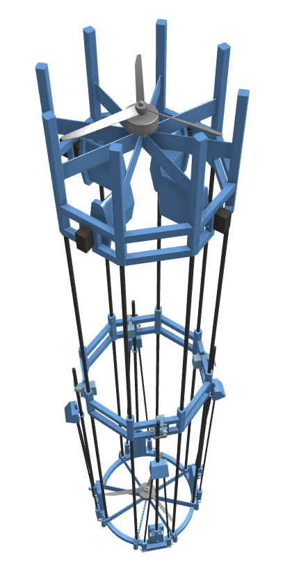
June 4: The CAD model is taking shape
Today I've made the top assembly that holds the upper motor and the 4 servos with TVC vanes. I've chosen to use Corona DS-919-MG servos, as they are fast and precise; and Emax ECO II 2807 1300KV motors, as they provide the most thrust for their range at a really affordable price too.
Next I'll make mounts for the batteries, ESCs, PCB and motors (right now they're on top of the struts and they need a mount to be screwed on). With this I should be able to slice the models to know their weight and calculate the TWR of the rocket.
Time spent: 3h 30min
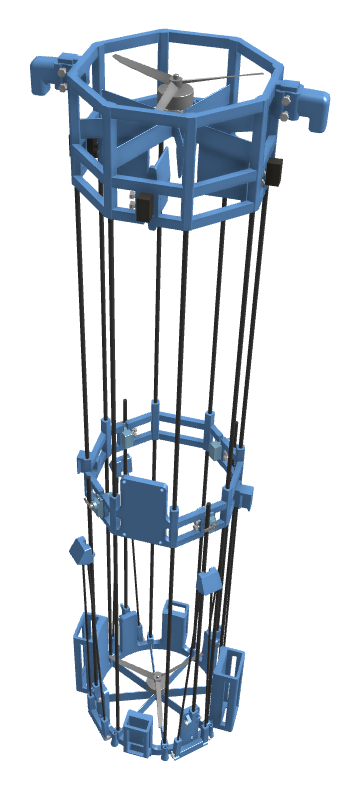
June 6 Log 1: The CAD model is finished!
Today I've made the battery, ESC, PCB and motor mounts. I've also added attachments for catch pins and for securing the rocket to a test stand which I plan on using for tuning the control system.
With this the CAD model is finished. I've sliced all of the parts and determined that the TWR of the rocket is around 2. This is in the range that I was hoping for, as I want to have margin for if the rocket ends up weighing more or it produces less thrust. I will keep it at this scale and with a coaxial configuration, as it's simpler and has a similar TWR.
Next, I will do more research on batteries and ESCs to see if what I've been using for now is the best option. After this I will begin designing the avionics and prototyping mounts and attachments.
Time spent: 4h
June 6 Log 2: Research on batteries and ESCs
I've decided to switch from two 3S batteries to two 6S batteries. This simplifies wiring, as I would have to find a way to connect the 3S batteries in series while keeping the cables as short as possible, as making them longer could damage the ESCs.
For the ESCs I've chosen to use the SURPASS HOBBY Flier 60A, as it's cost effective and it provides a 6V 8A output to power the rest of components.
Time spent: 1h 30min
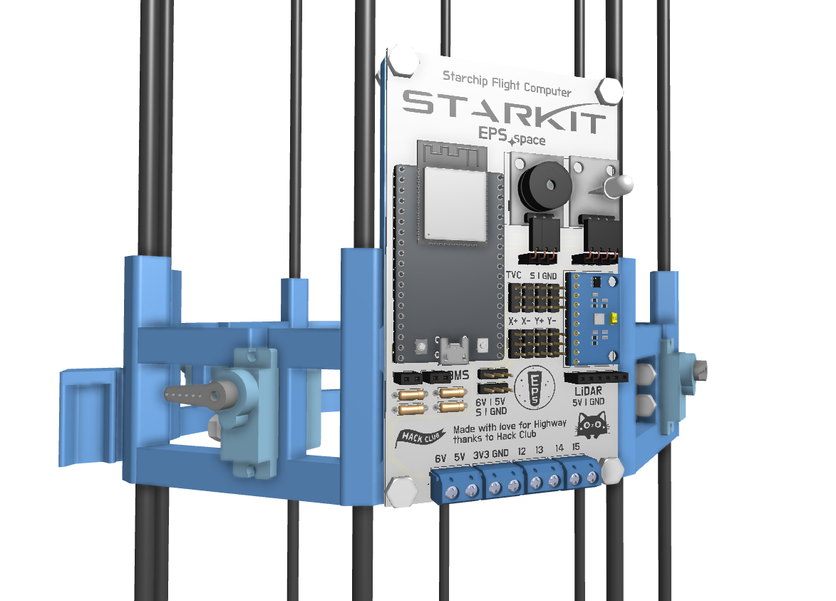
June 7: Research on avionics + beginning making the BOM and PCB
Today, I've made research on avionics components and chosen to use the following:
- Controller: I've chosen the ESP32 as it gives me enough processing power and built in communications
- Altitude measurement: I've chosen the TF-Luna LiDAR, as it's accurate and doesn't drift over time. While this sensor limits hops to up to 8 meters instead of the 10 meters I was aiming for, I think this is a fair tradeoff as upgrading to a 10 meter LiDAR would be twice as expensive.
- Orientation: I've chosen to go with an MPU-9250 IMU (Inertial Measurement Unit), as it's cost effective and widely used
- Communications and data logging: I will use Bluetooth, provided by the ESP32. I will monitor data and control the launch countdown from a laptop and the data stream will be saved on the computer.
- I will also use a voltage regulator for the LiDAR, resistors for measuring the voltage of the batteries and an LED and a buzzer for state indication
With this, I've updated the CAD model to house the new components:
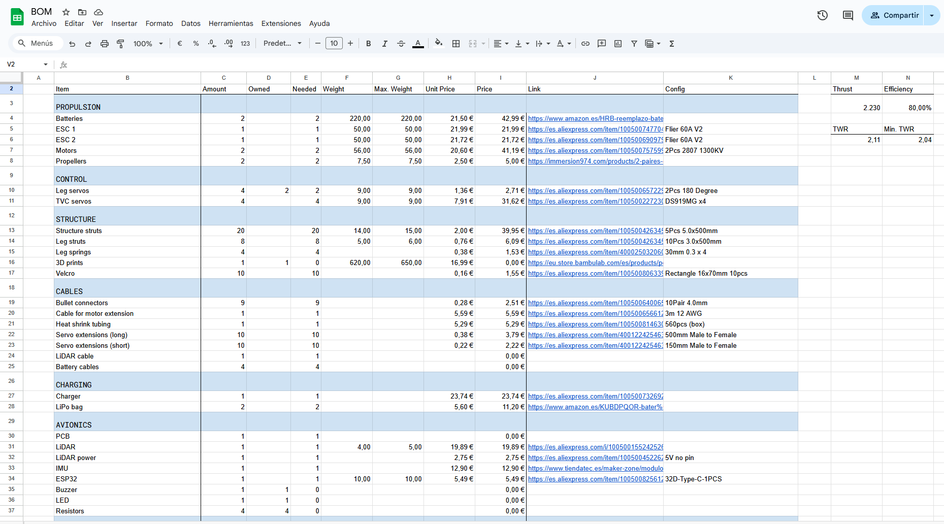
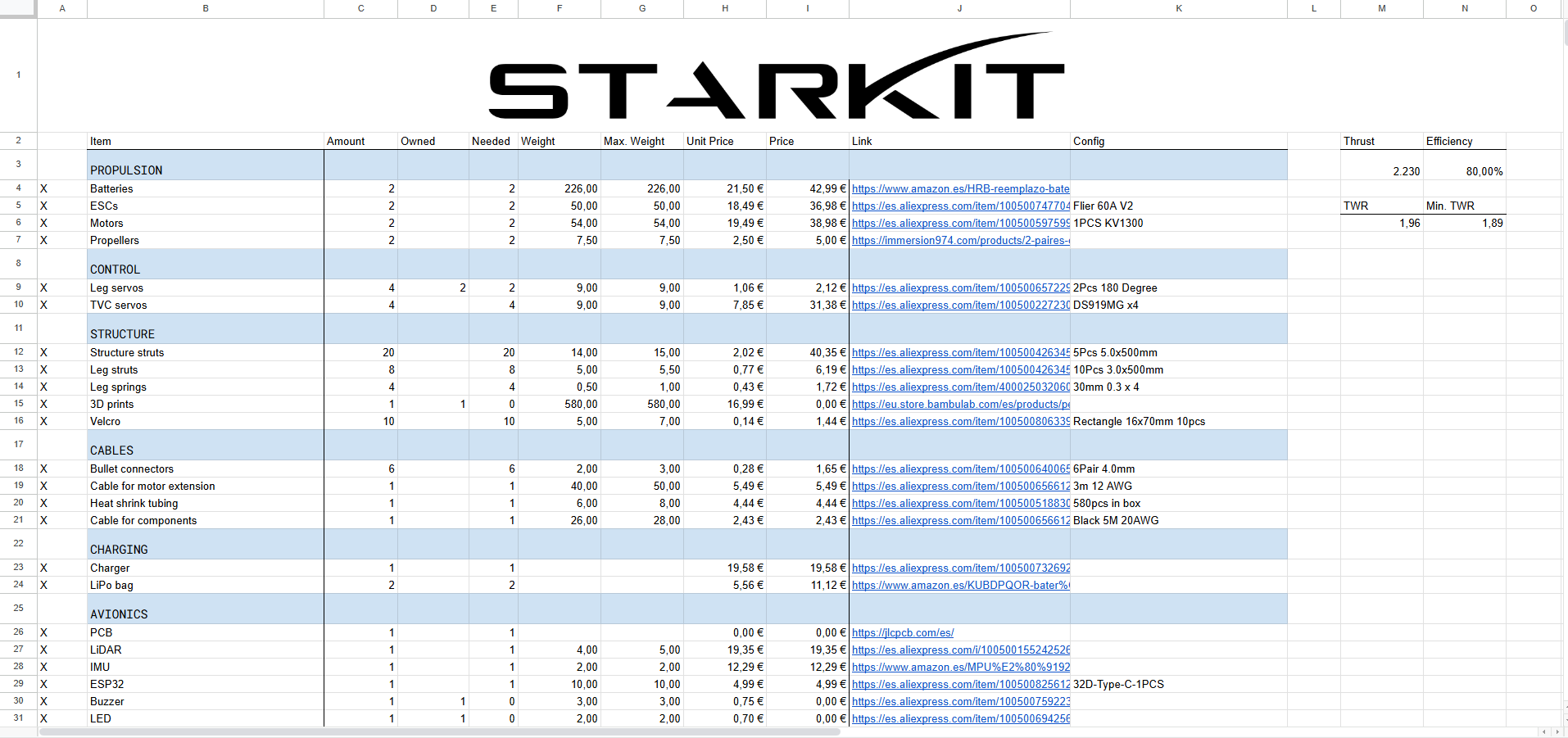
Next, I've begun making a BOM so that I can keep track of the price and the weight of all components. I've also chosen a charger, a LiPo bag, a magnetic propeller balancer and extension cables and connectors:
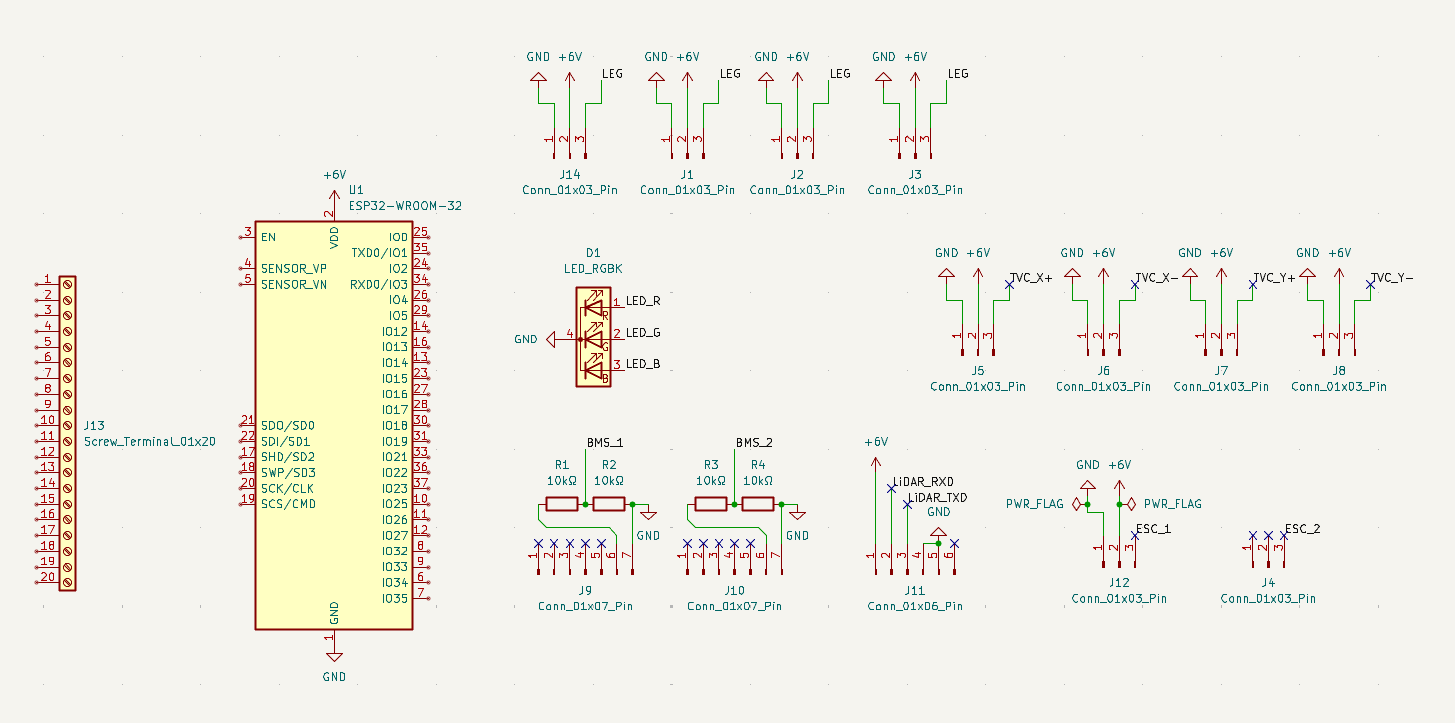
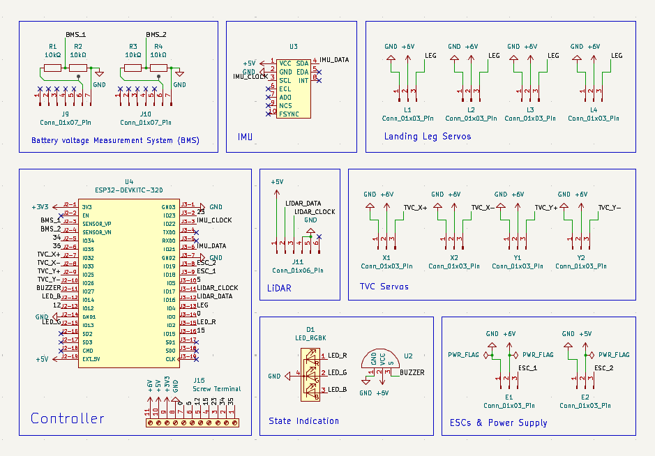
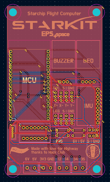
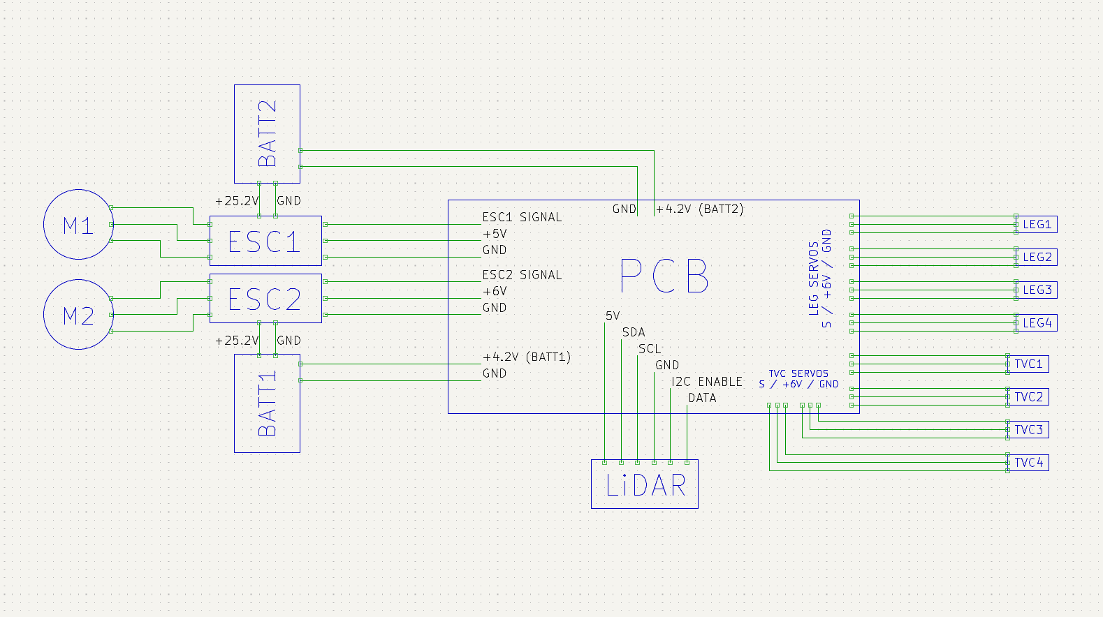
Finally, I've created a new KiCAD project and I've begun making the schematic for the PCB and some custom symbols.
Time spent: 7h 30min
June 8: Finishing the schematic
Today I’ve created custom symbols for the ESP32, the buzzer and the MPU9250. With this I’ve made all the connections and finished making the schematic. I've also realized that I can configure one ESC to use 5V instead of 6, eliminating the need to use a voltage regulator for the LiDAR. Next, I’ll create custom footprints and start making the PCB layout.
Time spent: 5h 30min
June 12: Starting the PCB layout
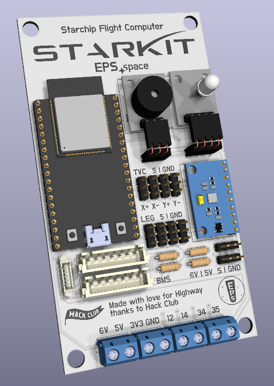
Today I've created or downloaded most footprints and 3D models and I've placed them on the PCB layout. This is my first PCB and I really like how it's looking so far. Next, I'll place the missing components and models and route the remaining traces.
Time spent: 6h
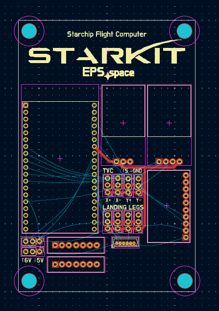
June 13: Finishing the PCB
Today I've finished making and downloading the remaining footprints and 3D models, arranging the components on the PCB, routing the remaining traces and making the silkscreen. With this the PCB is complete!
Next, I'll finish the BOM and revise all components. After that I will send my project to online forums to make sure I haven't done any mistakes and that I have the most chances of succeeding.
Time spent: 5h
June 14: Making a Unity simulation
My Internet decided not to work today so I started making a Unity simulation to better understand how the flight software would work. In the simulation, the rocket is capable of holding a predefined altitude and correcting its orientation with only the data that the real flight computer would have.
The following days I will work on the BOM and I’ll continue with the simulation after getting the project approved.
(Screenshot coming whenever I restore my Internet)
Time spent: 3h
June 15 to 19: Updating the BOM
Over the past few days I've revised every component of the BOM and added some that were missing. I've gone through every component, searched for cheaper and better alternatives, and I've updated their weight and price. I've ended up switching a few connectors, so I will have to update that in the PCB as well. My Internet is still dead on my main PC so I will update the components and reroute the traces as soon as I can.
Time spent: 10h 45min across all days
June 21: Updating the PCB
In a combination of luck, hours of troubleshooting and miraculous circumstances I've managed to restore Internet connection on my main PC at about 1kbps. I've sent the KiCad files to my email and managed to open them on another computer.
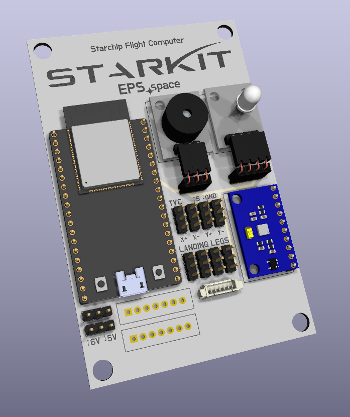
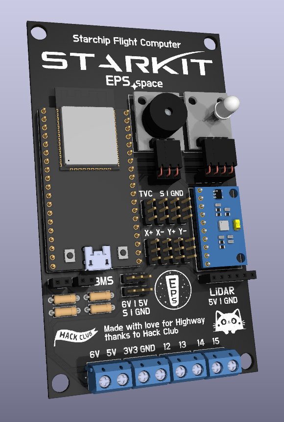
After that I've updated the connectors that I had changed and I've rerouted the traces. Not only does the new design look nicer but it also has enough space to fit a picture of a silly kitten (the name Starkit
comes from my obsession with cats anyways). I have also exported the PCB 3D model and attached it to its mount in the CAD model.
Time spent: 4h 30min
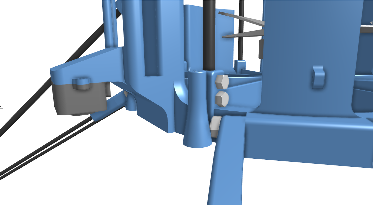
June 22: Tweaks to the CAD model and asking for design feedback
Today I've updated the CAD model slightly by adding bolts to lock carbon fiber rods to 3D prints, eliminating the need for glue. This should allow me to more easily replace rods or 3D printed parts when they break.
After that I've written about the design of the rocket and asked for feedback on RC Groups, where there are people much more experienced than me that actually know what they're doing. With this I hope to make sure that I didn't make any major design flaw and that I have the most chances of succeeding.
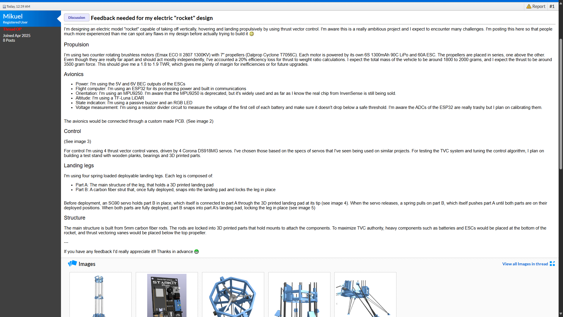
Time spent: 3h 30min
June 23: Preparations for submitting
People in RC Groups haven't spotted any major design flaws so far, so today I have started preparing my project for submission!
First, I have converted the BOM to CSV format and uploaded it to the project repo. Next, I have moved all of the PCB dependencies to a single folder and uploaded the KiCAD project to GitHub as well. Finally, I have updated the README following all of the submission requirements, including making a wiring diagram:
Finally, I have posted the project in #highway-pitstop and I'll see how it goes!
Time spent: 3h
After getting approved
July 3: Buying the parts!
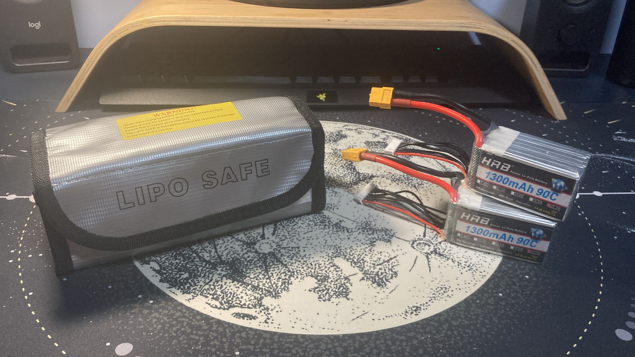
I've got approved and I've just received the grant! Today I've checked which parts I could buy and receive in time before my trip and I've ended up buying the batteries and the LiPo bags.
Time spent: 1h
July 4 to 6: The first parts have arrived
Over the past few days I've received the batteries and LiPo bags and I've uploaded their receipts to HCB!
July 8: Prototyping servo mounts
Today I printed the landing leg servo mounts to see how they would behave.
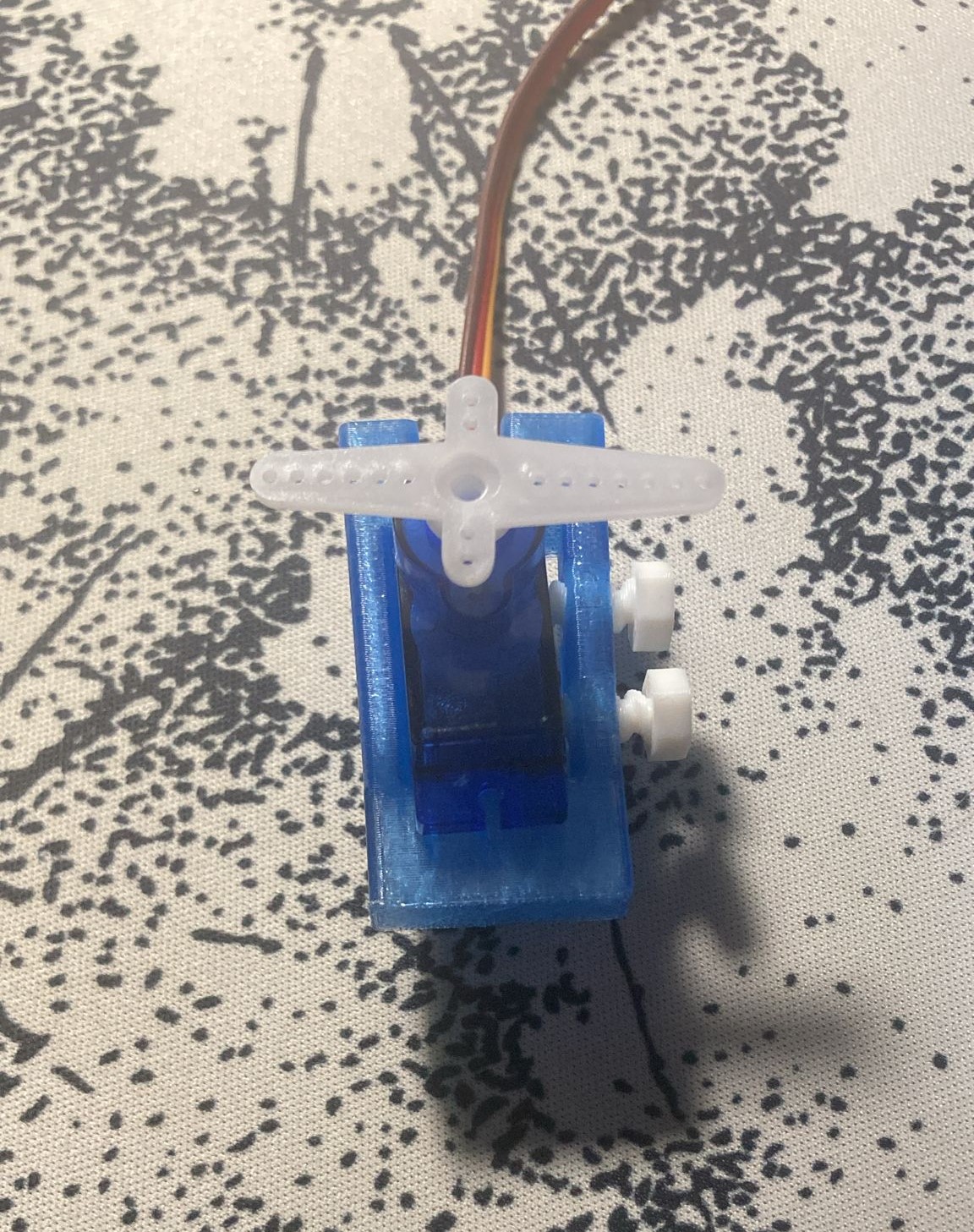
Turns out, not really great. I was hoping for the friction from the bolts to prevent the servo from slipping, but this is not the case. In this prototype, the print can bend slightly, which wouldn't happen in the real thing, potentially increasing the friction. However, I've decided to redesign the servo mounts to make sure the servo will stay securely in place.
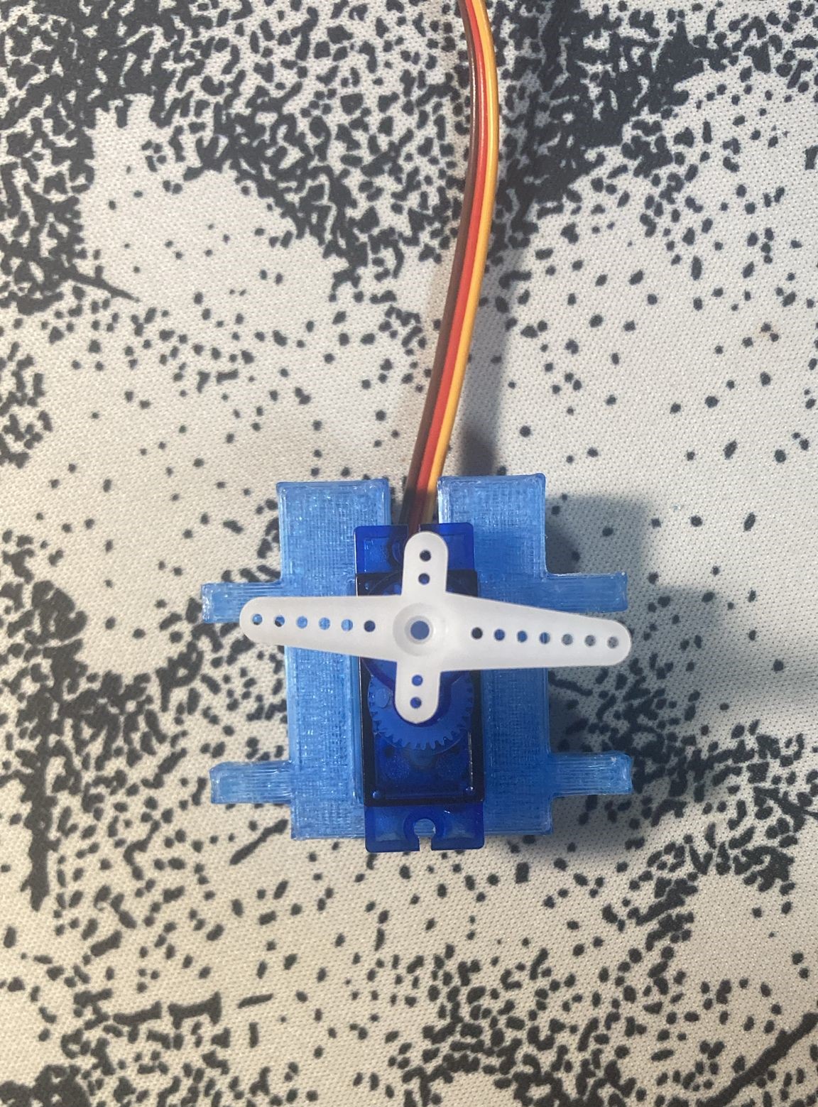
In the new design, the servo is pasted into a mount which can be bolted into the rocket's structure. This allows for easy replacement in case something breaks.
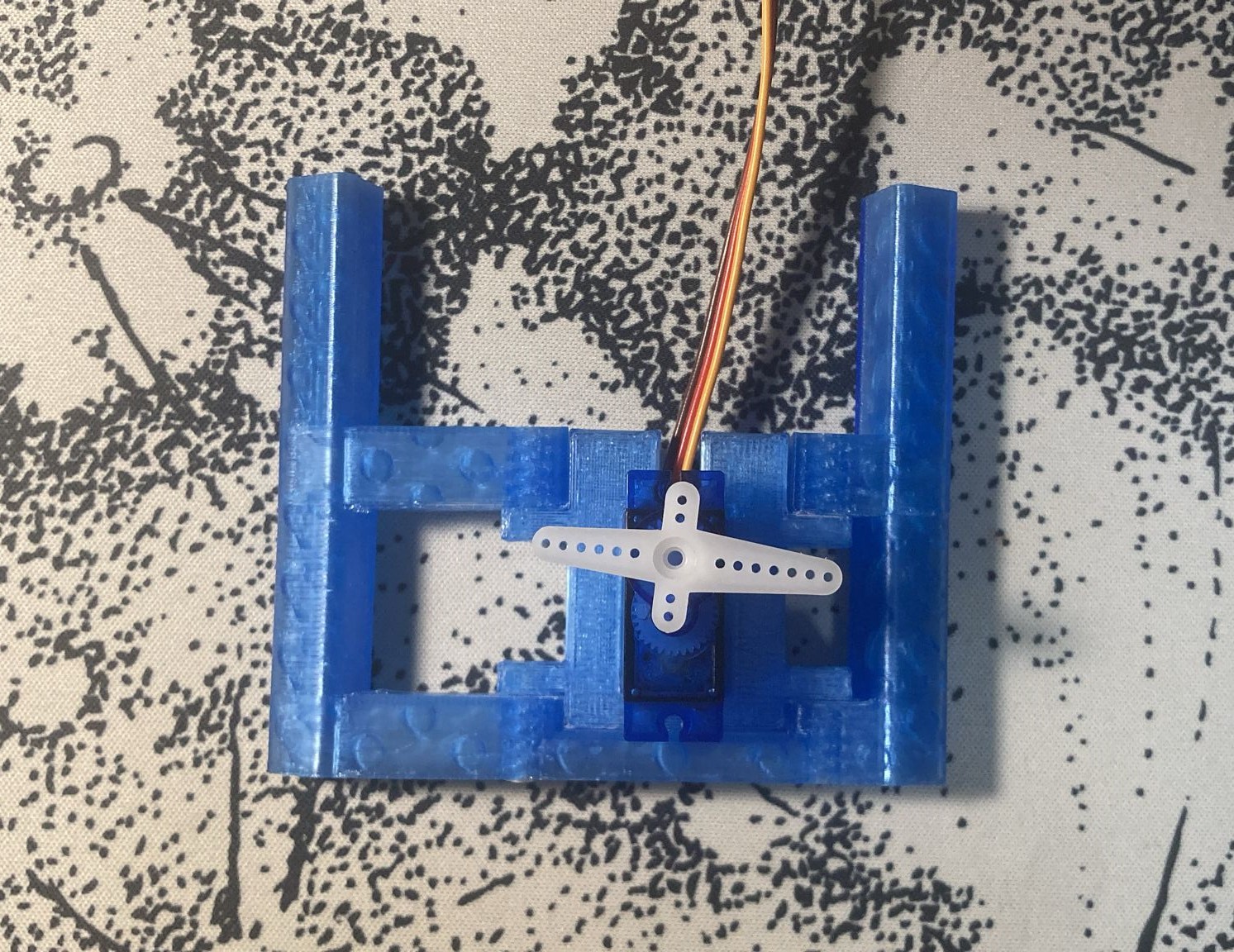
I printed a small section of the structure, which includes attachments for the rods which I plan on testing once I buy them. The bolts couldn't get in and I realized the rod attachments could flex, so I've made the necessary adjustments in the CAD model.
Time spent: 6h
July 15: Adding items to my cart
Today I've added the items on AliExpress to my cart so that I can buy them when the shipping date is when I'm home.
Time spent: 45min
July 21: Buying more parts
Today I've bought the carbon fiber rods, the IMU, the motors and the TVC servos.
Before buying them, I realized that the IMU had no reviews. Amazon, where I was planning to buy it, is plagued with fake MPU-9250s without magnetometers. For that reason I searched for other sellers and I found one on AliExpress with good reviews and a similar price that explicitly stated it used the original sensor with the magnetometer. I talked with my reviewer about the change, and after getting approved I bought all the parts!
Time spent: 1h 15min
July 23: Attempting to buy more parts
Today I planned on buying the remaining items on AliExpress. I had already added them to my cart, and there happened to be a huge sale running that allowed me to get the LiPo charger for half the price. Now I just had to pay, or so I thought.
When I tried to pay, AliExpress declined my card for security reasons
. However it still had placed the order but I had to pay it within a certain timespan if I didn't want to get it cancelled. So I went through every one of the items and paid for them, except for the ESCs, the charger, the LiDAR and the leg springs, which I still couldn't pay. I kept trying and I eventually could pay the springs. Except because AliExpress chose to cancel my order right afterwards and now a refund will take 3 to 15 business days.
At this point it was 12PM and I decided to continue trying the day after. This meant that the order for the LiDAR would be cancelled, but that's fine as I didn't get any discounts on it. If I don't manage to pay for the charger tomorrow though I will lose $12 as I used my discount for that.
Time spent: 1h 30min
July 24: Paying for the remaining parts
Today I attempted to pay for the remaining parts but it kept failing. As a last resort I called my father and we ended up opening a new PayPal account linked to the HCB card. This finally worked, and after paying for the ESCs and charger I ordered the remaining parts which I couldn't buy yesterday: the springs, the LiDAR and cables, which I couldn't add to my cart in the first place because of my order being too large.
I also noticed I had received the reimbursement from AliExpress, the one that allegedly would take 3 to 15 business days. Anyways the only things left to buy now are the propellers and the magnetic balancer. Except because I found out the store from which I was going to buy the propellers from doesn't ship anywhere at all, but that's a future me problem.
Time spent: 1h
July 25: Finding new propellers
Today I wanted to buy the propellers, so I started looking for other sellers that would ship to my location. However, there weren't many as the propeller I chose is discontinued, and the only ones that I could find were way more expensive. I chose this propeller because of the availability of test data with the motors I'm using, but I started to look for other options. After some time I found out that the manufacturer of the propellers had made an updated version. Although I don't have test data for it, it should behave roughly the same. I found the propeller on Banggood at a good price, and I bought it after talking with my reviewer about the change.
Time spent: 1h 15min
July 26: Buying the propeller balancer
Today I bought the propeller balancer and for once everything went according to plan. The only thing left to buy now is the PCB, which I'll do once I test the avionics.
July 28: More parts have arrived!
Today the carbon fiber rods and the IMU have arrived!
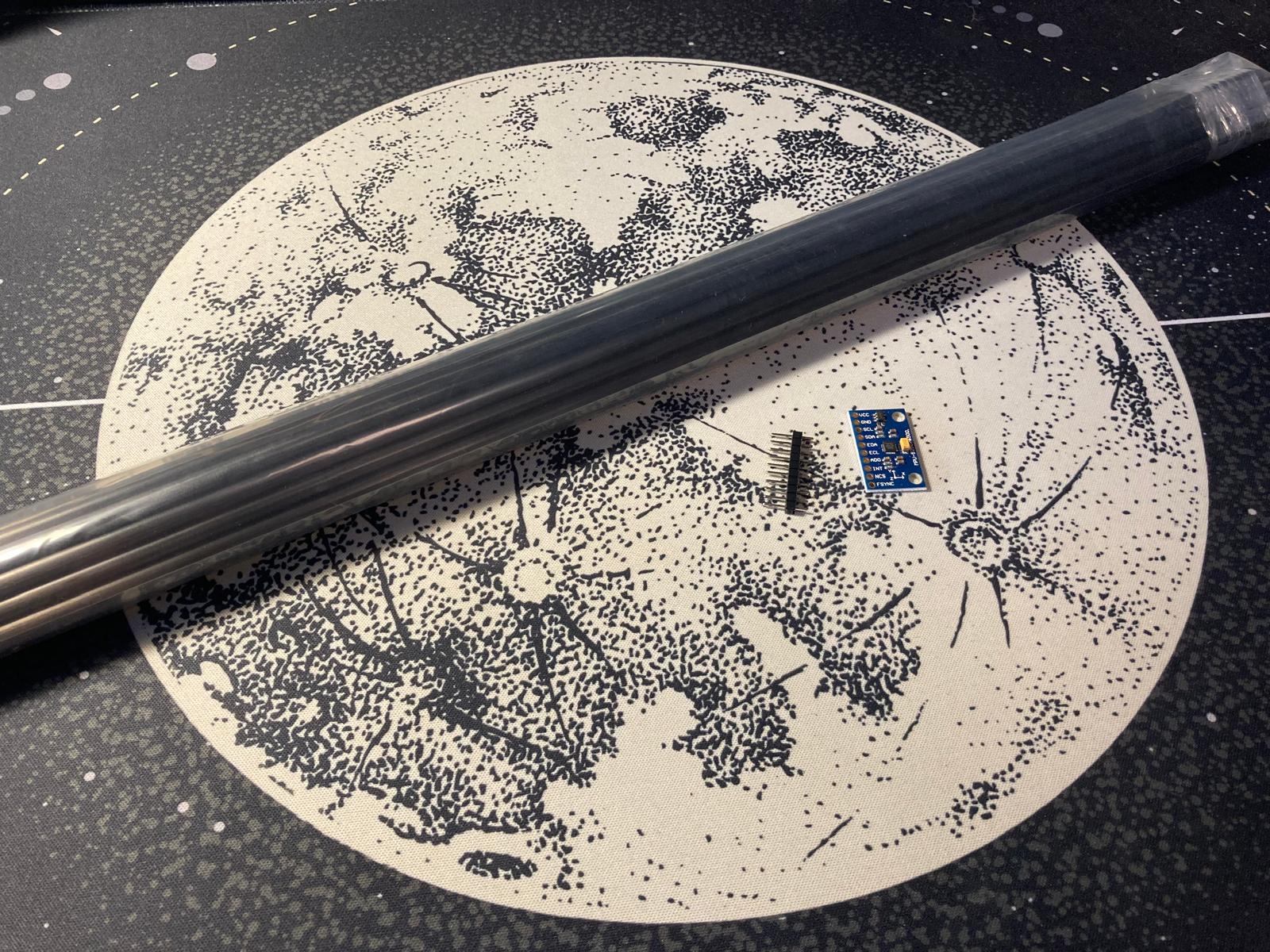
July 29 Log 1: The whole AliExpress warehouse has arrived at my room
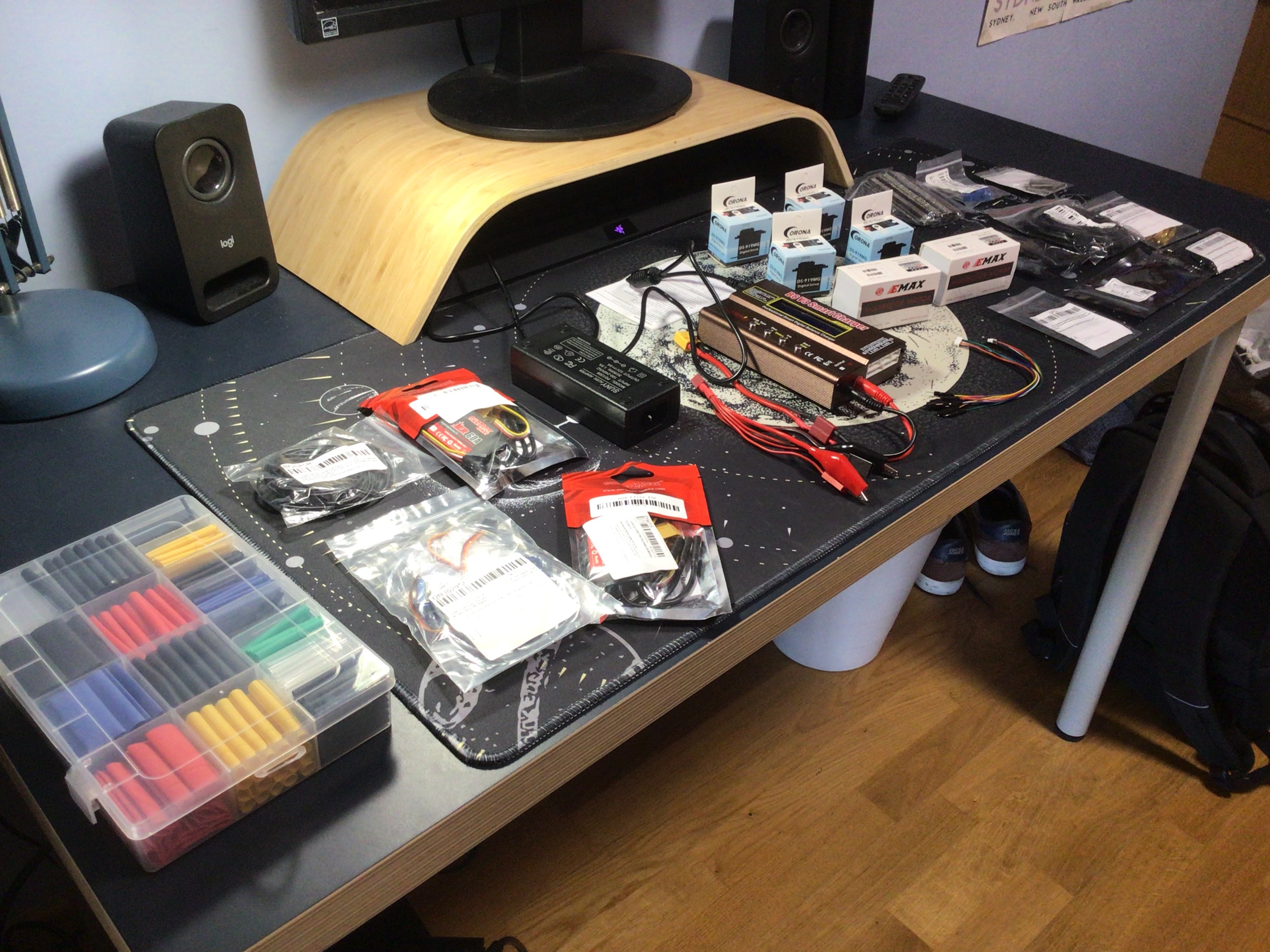
I'm not even going to try to list everything that has arrived today. It's just insane to think that I got all of this for free.
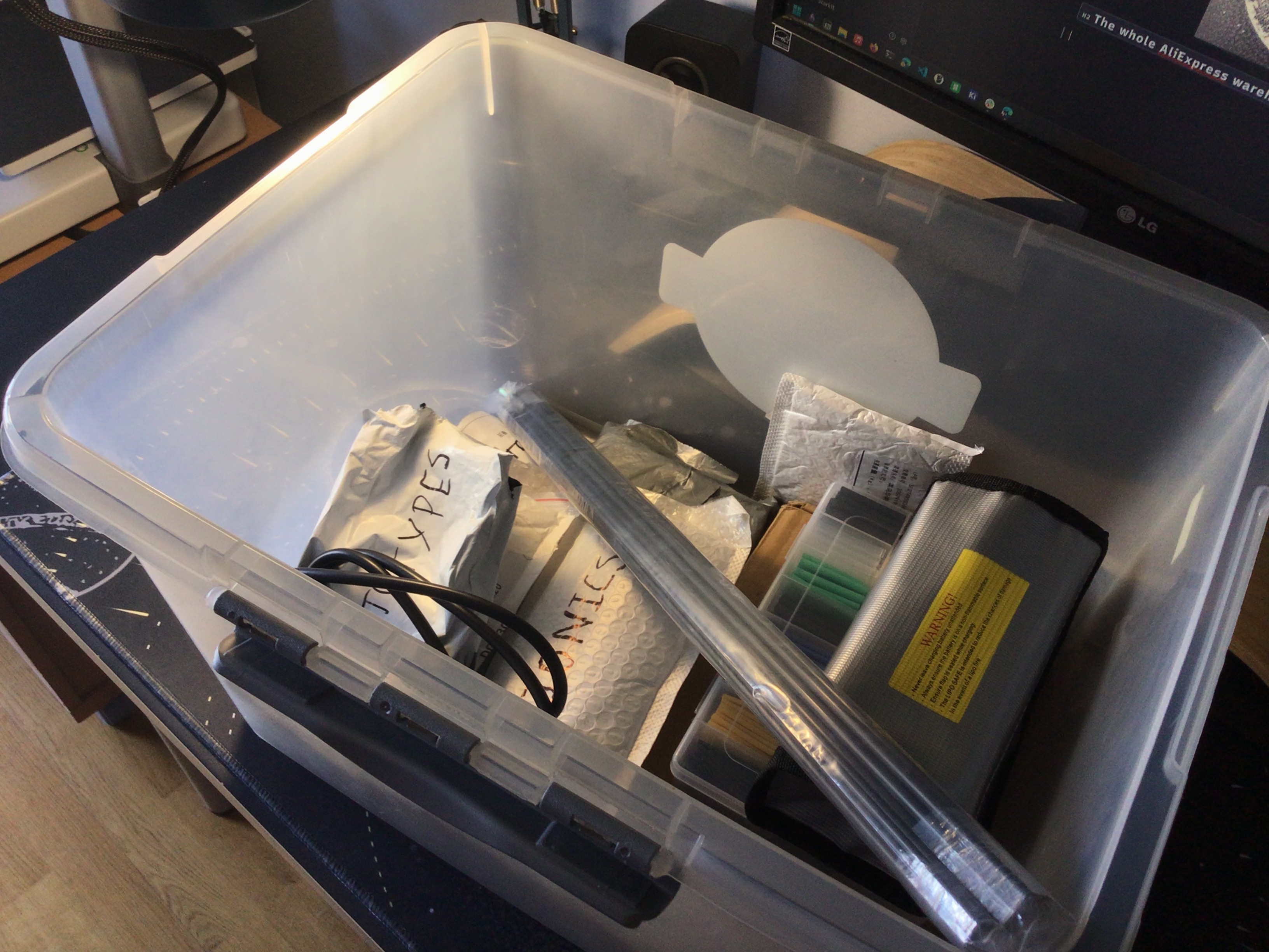
After checking that everything was in a good state (and realizing that the AC cable for the charger had the wrong plug - thankfully I had spares), I organized everything into bags with different categories and all of that went into a box for everything Starkit.
Time spent: 2h + 2h 30min organizing the rest of my electronics
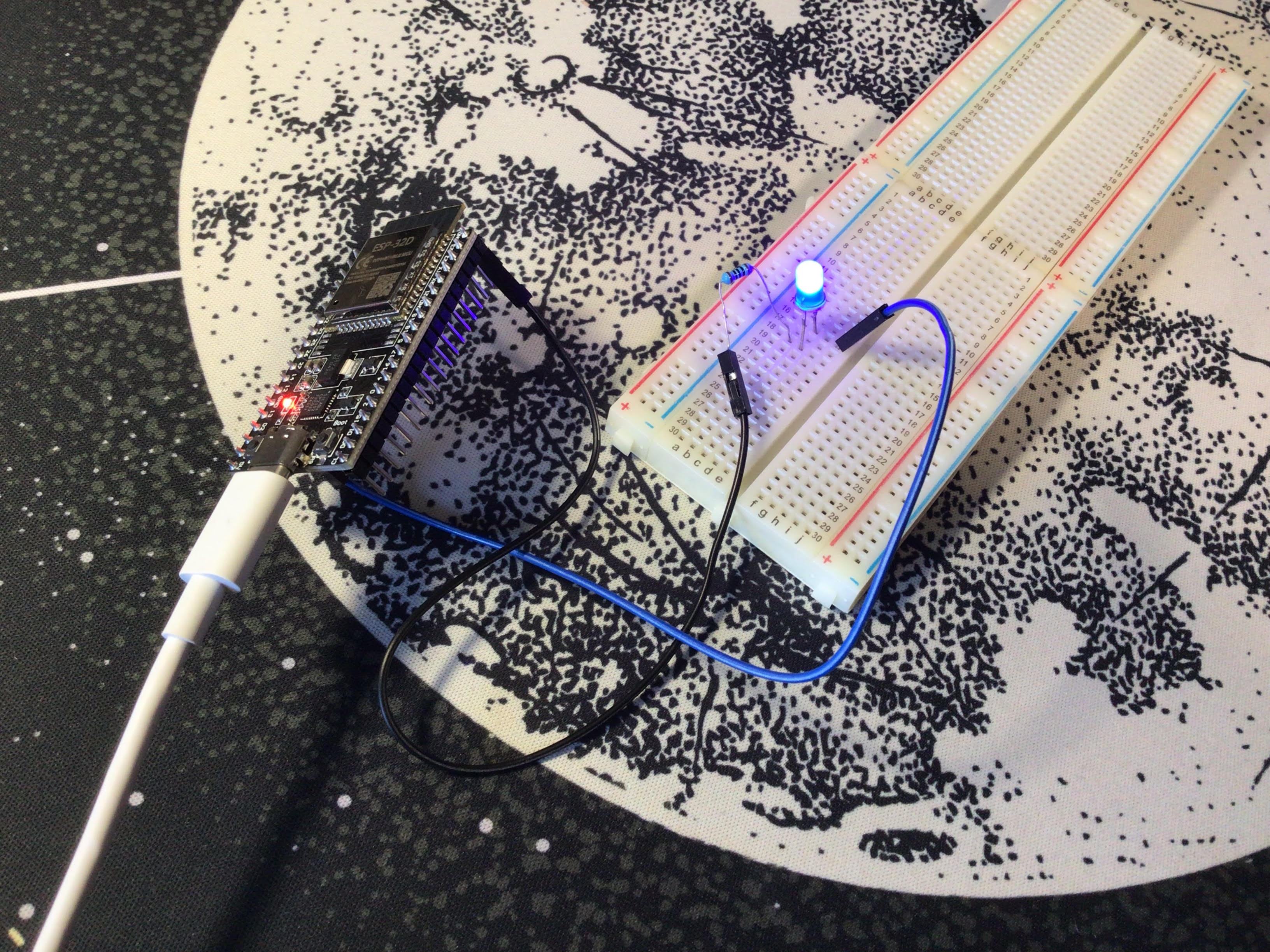
July 29 Log 2: Testing the ESP32
The only thing left to buy is the PCB, but before I do that I have to verify that everything works fine as it is connected in the schematic. However, I decided to test every system in the avionics separately before assembling the whole circuit.
I had only worked with Arduinos before, not ESP32s, so I started by testing uploading an sketch to the ESP32 first. I followed through a 20 minute video on how to setup PlatformIO for ESP32 development. I installed the necessary drivers and adjusted the PlatformIO project settings but nothing worked at all. I tested different cables and different sketches but still I couldn't get it to work. Then I followed through a 1 minute video on how to setup Arduino IDE for ESP32. It worked on the first try an I got an LED to blink:
Time spent: 1h 15min
July 30: Testing the LiDAR and the TVC servos
I started by testing the LiDAR with the ESP32. In the real thing, the LiDAR is powered by the BEC output of one of the ESCs. As the ESP32 is a 3V3 device, I had to use an Arduino UNO to provide the power. I made the following circuit:
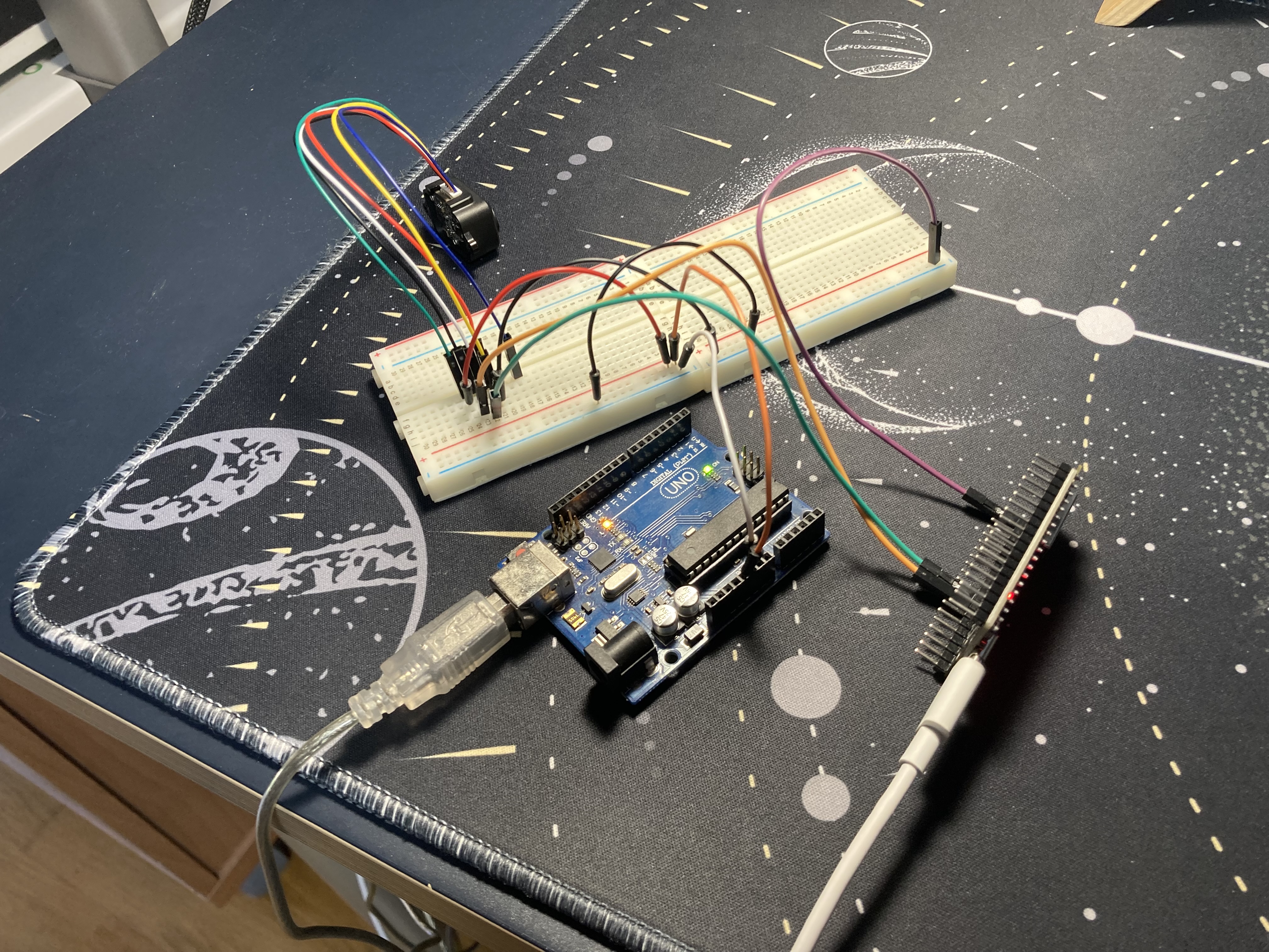
After finding the right library and tweaking it to work with an ESP32, I got it to work pretty well.
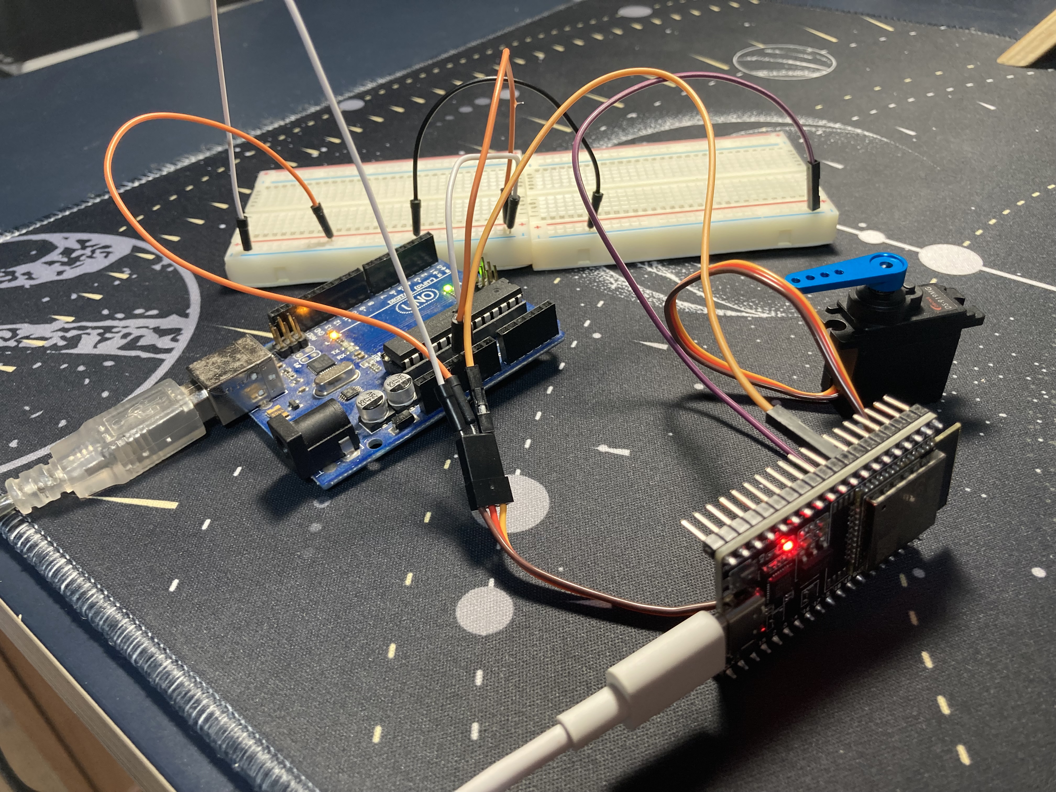
Next, I tested the TVC servos. I used the same system in which I get the power from an Arduino but all processing happens on the ESP32. I got it working in no time and I was honestly surprised with their speed. A huge upgrade over the SG90s I had always worked with.
Time spent: 2h 45min