
netherrack home server
mini home server for backups or photos!
Total Time Spent: 29 hours
Days 1 and 2 - Documentations and Planning - July 18 and 19
Time Spent: 3 hours
I read through the documentation of the Raspberry Pi CM5, the CM5IO board and the capabilities it had. I did a bit of research on where I could source my parts from and what features I should implement. I didn't plan on using any wireless capabilities, relying on ethernet instead. I also researched and tried to understand the functioning of differential routing and why it is necessary for USB, M.2_PCIe and Ethernet. I managed to create a rough design of how I wanted it to look like. A square board, mounted vertically (like in a PC) with easily accessible USB, Ethernet and M.2 ports. I wanted the front to be acrylic panel so that the design was easily visiblem, and the rest to be PLA. The HDMI was routed near the top so that it could be used for debugging rather than for display (I plan on SSHing into it).
Day 3 to 5 - PCB Schematic - July 20 to 22
Time Spent: 6 hours
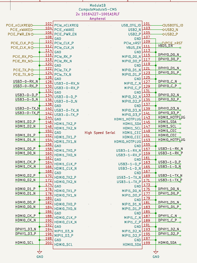
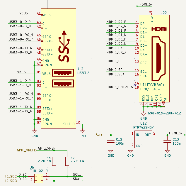
I started working on the schematic with heavy references from the CM5IO board (thank god for open source). The CM5IO board also included libraries for everything I needed (except the 10164227-1001A1RLF connector, more on it later). I made a schematic from scratch initially, but since it was almost similar to the CM5IO board, I decided to use the necessary components fromm there (capacitors, power, etc.). I also modified the ports I needed to include 2x USB, 1x Ethernet and 1x HDMI (along with the USB-C power port). I added a 4-pin fan header for when I might add a fan later, although I don't plan on using it since the CM5 is pretty well cooled with only a copper heatsink.
Day 6 to 9 - PCB Layout - July 23 to 26
Time Spent: 11 hours
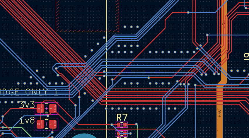
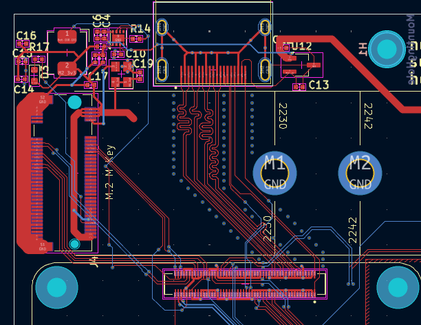
I spent the next couple of days working on the PCB Layout. I wanted to keep the square design so naturally I started with the edge cuts. I then started placing my components which was confusing because of the sheer quantity of traces that needed to be decoupled or routed. I tried to follow to documentation, so I imported the rules and nets from the CM5IO board. I made sure to keep the HDMI port close to the top edge so I could route it easily. The board's length was quite bottlenecked due to the length of the M.2 Socket, so it had to be a bit larger than I hoped for. I rerouted it atleast 10 times in the first 3 days, before I watched a guide and learnt more about differential routing for high speed traces. Turns out, I don't need to length match the traces for the M.2 port to a great extent, and I don't need to match intra-pair RJ-45 traces either. This greatly allowed me to speed up the routing process.
Day 10 - BOM Assembly - July 27
Time Spent: 2 hours
I spent this day selecting components across PCBPower (my fabricator of choice) and LCSC components. Most components like the capacitors were sourced locally to reduce shipping and freight charges. When I was exporting the PCB CPL files, I noticed that the CM5 was 1 thing, not 2 seperate board-to-board connectors. I had to look for the 10164227-1001A1RLF connector. I managed to export the gerbers with the CM5 and the CPL files with the connector. Tommorow, I plan on deisigning the case and front panel for the board.
Day 11 and 12 - Case design - July 28 and 29
Time Spent: 7 Hours
Over the course of two days, I spent a lot of time working on the case for this project. My idea was to have a Standing rack with a side acrylic panel to see through, and all the ports on the side. HDMI would be on top because of space, and also because I intend it to be only used during debugging. I also plan on using M2.5x25mm screws but those are a bit hard to find. I completed a render and design for the case, and am ready to export everything. I also received a component sourcing invoice from PCBPower for the prices on all the components I need, which isn't too expensive (30$). I just need to find a similar Magjack as the one in my board, but if I can't find it then I will have to replace the specific port with a different one.
I started designing the case in fusion 360, which despite barely running on my pc, I have become quite experienced in. I started by drawing a sketch based on the PCB and importing the STL (I later learned STEPs work too, albeit with a slightly different process). I then modelled the case around the PCB model, making extrusions and chiseling cutouts for the ports. I did not put a fan in this iteration of the case, as Passively cooling the module with a copper heatsink and some airflow holes should be fine. I also made sure to add a step file of the CM5 board but it looked piss yellow so i just left it out. I managed to extrude an acrylic panel on the top with the screw holes. I then made a render with all the components neatly together!