
RC Car with an Arm
An RC car with a 4 axis arm
15th of May
highway was just announced :D
Anyways I was coming up with a few project ideas when suddenly I thought: GUN\ But a gun is boring tbh. It just shoots and does weird stuff.\ So what could be better than a gun you may ask?\ A gun.... ON WHEELS.\ But what could be better than a gun on wheels?\ A REMOTE CONTROL GUN ON WHEELS.
You heard it here first folks. thats how we roll.
Anyways now its time for my suoer cool progress report\
insert super cool name for the project report\
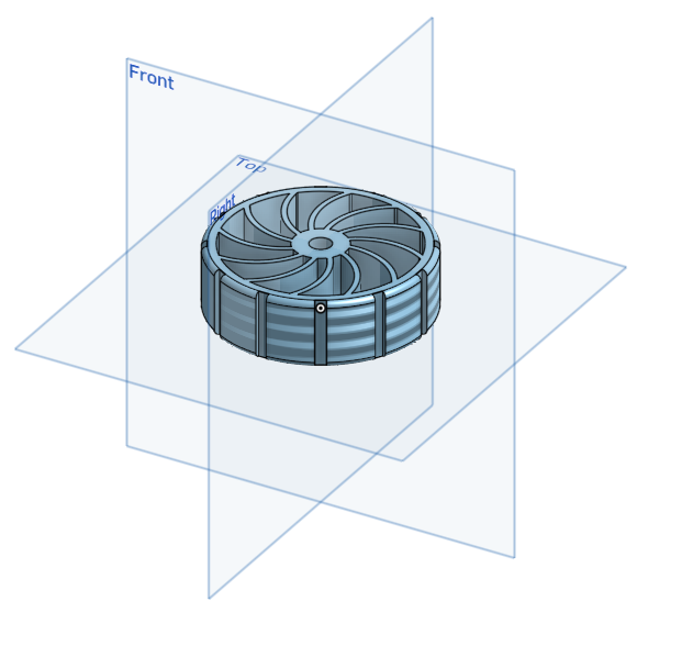
I did some cadding today for like an hour or 2 and I made a wheel :D\
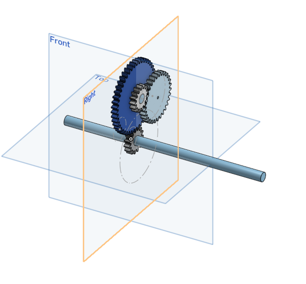
I also made some gears and mechanical stuff for the back tires.\
thats about it tbh.\
 \
\
Anyways time for a farewell my good friends, \ Until the next we meet.
Time spent: about an hour
16th of May
hello. I am writing this on the 17th cuz i forgot to do it yesterday.\ anyways I dibbled a bit in the cad but mainly started up with my pcb and electronics.
so I started doing pcb stuff. but I came across a problem.\ I dont want to buy and use a motor driver. but I need the dc motor to be able to move forwards and backwards.\ after a bit of thinking, i remembered an old school project where i did that but with a physical switch.\ now the question was, how do i make that into something i can turn on with gpio pins?
after a bunch of thinking and designs later, I reinvented the H bridge.\
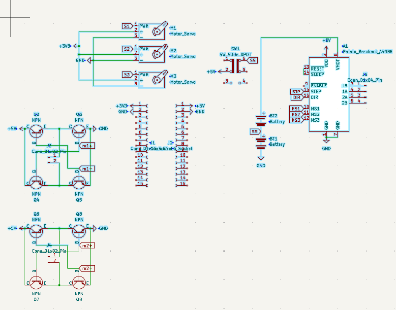
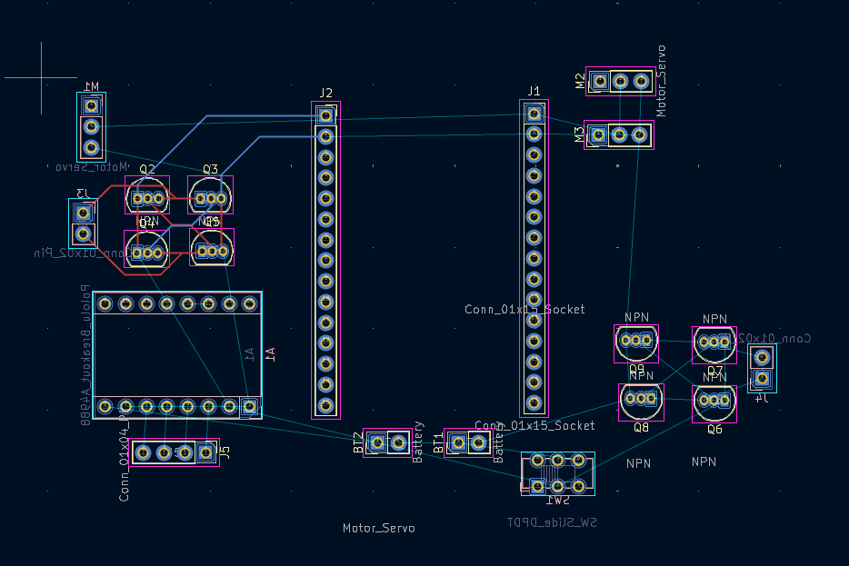
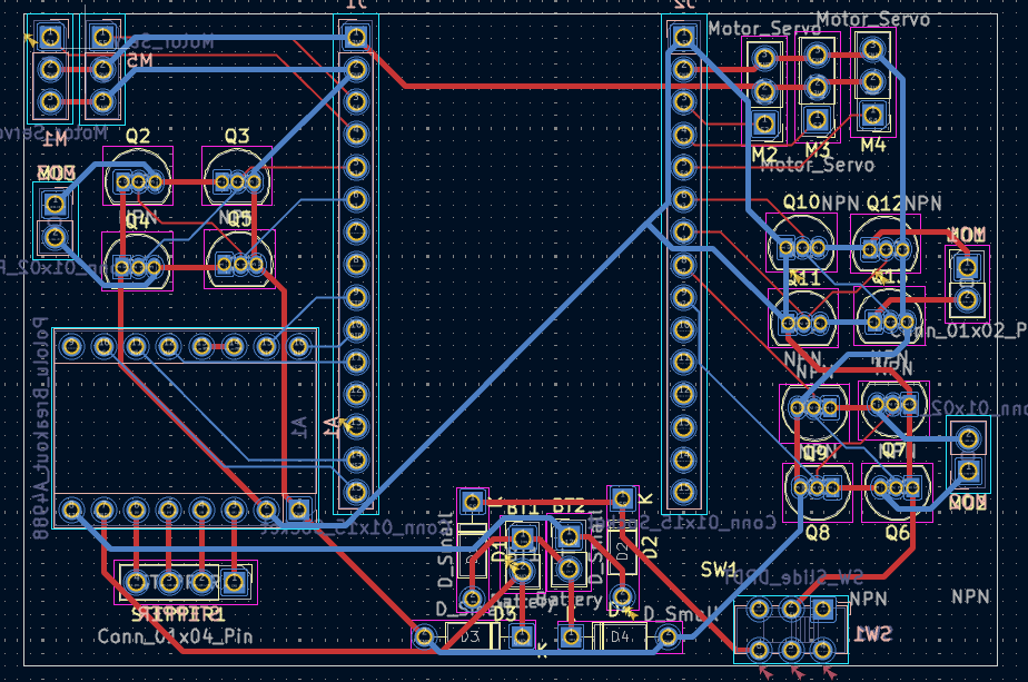
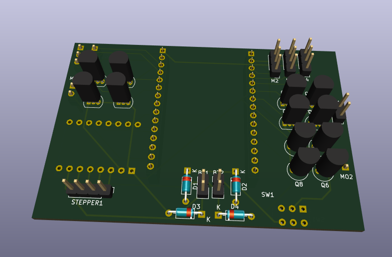
after that i started work on the schematic and pcb and ended off the day looking like this:\
 \
\
oh yeah i decided to use an esp32 as the mcu so i could use esp-now as the communication between it and the controller.
Time spend: 1-2 hours(I forgot but somewhere in that range)
17th of May
okay time for todays update. im gonna talk as if you have image references and then add the images in later cuz im not bothered rn tbh.\ if you can see images here then congrats, you came after i added images.
Okay so with my schematic i added a whole bunch of stuff like the stepper motor, more h-bridges, more servos, battery connectors, etc.\ also that weird stuff going on with my battery connectors is me trying to make both a 6V and 12V power supply come from 2 6V batteries.\ so the diodes limit the flow so it doesnt blow up on itself and the batteries are aranged so they are both in series and in parallel at the same time.
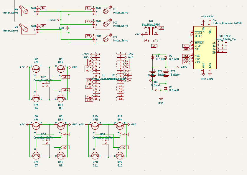
I also added more h-bridges and servo spots than im actually gonna use\ the thought process is that if in the future i wanted to change up the functionality, then i could use those extra ones if needed. plus I had space anyways.
 \
\
tmrw im gonna probably gonna go and start on the internals cadding. but i need to do meth and physics hw first :(\ anyways bye
Time spent today: 5 hours
18th of May
1am
so i was looking into the esp input voltage and turn out it can handle a 12V input.\ but that diode mess was not for nothing. I still need it for my motors.\
UPDATE: im just gonna use a buck converter. I dont wanna gamble on my idea just to save $2
found a nice battery so gonna save the link here: https://www.amazon.com.au/cart/smart-wagon?newItems=af51fb0b-661d-4de9-b8e5-c46f956c932f,1&ref_=sw_refresh
Hours spent: 1
21st of May
I'm finally back
anyways I am in pain\ onshape sucks\ and linux literally doesnt have any better options.\ so until i get a new laptop, its gonna be incredibly slow production.
anyways what i did today:\ lots of cadding and stuff.\ made some ideas for suspensions\ got a lesson from my dad on how suspensions are stupidly harder to use\ settled on just hard connections\ now designing that stuff\ learnt how horrid onshape is for doing anything big of with lots of parts.
hours spent: 3
23rd of May
okay so i got sick yesterday and wasnt able to make an entry so im gonna summarise both days work today.
So first some yap. In approximately 11 hours and 35 minutes, the kickoff call will start. thats fun and exciting.
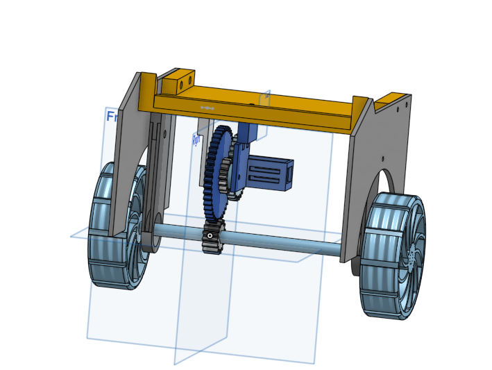
Okay so onwards to what I did.\ Yesterday I worked a lot on my back half of the car and did quite a lot of work and got most of the interals done for the back half of the car. And today I finished up those internals and got them at an acceptable standard for me.
 \
\
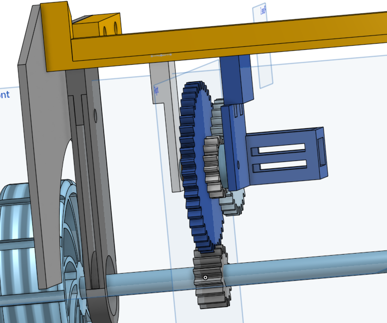
I also got started on the gun mechanism and roughly mapped out 2 of the axis for my gun to move around with.
 \
\
THE PROBLEM
So due to australian gun laws, it is illegal to possess, make, or hold schematics of any weapon. Toy or not.\ Due to this, my entire plan of making a gun on top of an rc car is shut down.\ So what can i do to solve this?\ Its an rc car with a 4 axis robotic arm on top.\ Instead of a ranged weapon, its a close combat fighter. /j
anyways thats my idea now so I need to go back and make changes to my pcb and bom. I need to add another stepper motor to my pcb(this is gonna take a big battery)\ My plan for the arm is to have 3 bending points and one spinning point. the bottom bending point uses a stepper motor for extra strength and the top 2 and hand will use servos the hand might use a 5v motor though. (havent decided yet)
hours spent: 8
24th of May
so today was the call for highway and it was peak.
today i started part research and a pcb overhaul to accomodate for the extra motors needed in the arm. now the problems with this: I found out that the transistors i am using can only handle up to 100 mA when i need about 1A to drive the motor. so thats a big problem. Next problem: Im using 12V motors and most mosfets i looked at cant properly fuction with 12V and a 3.3V trigger and the ones that do are all smd parts which are impossible for me to work with.
so my plan rn is to just leave this until i find a solution and start working on something else.
time spent: 3 hours
4th of June
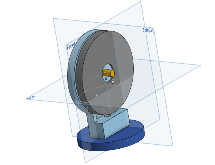
Im starting to work on this again and its pretty cool. I started on the arm since I am on a brain block on how to make the body.\ I made the hand part of the arm today.
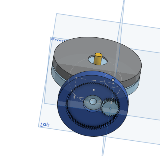
For the hand, I used a worm gear(i think thats the name) with 4 prongs.
It started with a spur gear with a massive centre bore, Then I made 2 cuts from the centre out and got left with ~200-230 degrees of gear.\ I made a sketch for the prong to attach to the end of the gear and extruded it out both sides to make a prong. I then put a zigzag on the end of the prong and added a chamfer.

I then spent an hour trying to learn how to make screws and made a centre screw for the hand.\ I then copied it 3 times around the screw to make it look like the picture above.
Next was the frame. This was the hardish part.\ I started by editing the prongs to add a centre hole for a bearing and put a rod through it\ Then I made corner frame parts by alligning the 4 prongs\ I also made some chamfers to make it look nice
Next was the motor holder, I extruded 4 corners and platformed around a rectangle that I made as a motor placeholder.\
Next i put a square to hold the 4 parts together with screws.
And that was my day.
Time Spent: 2 hours
5th of June
Today was highway call. today was cool because I finaly figured out a good way to make a turning system that I can implement into this.
I will add some more info later on it once I start thinking about it a bit more
Yeah i have no clue on how to do this.\ I wanna die\ why is this so difficult to figure out\ ooh wait\ new idea\ lemme make some sketches
Time spent: 30 mins
18th of June
okay I am gonna do a full redesign. Now it will use 4 motors(1 per wheel) so then turning will be a lot easier to figure out.
6th of June
New idea maybe works\ not known for sure\ but there is a chance