
Smart Desk Lamp
An ESP32-C3 based Desktop Light with capacitive touch and Home Assistant Integration
June 9th: Mockup
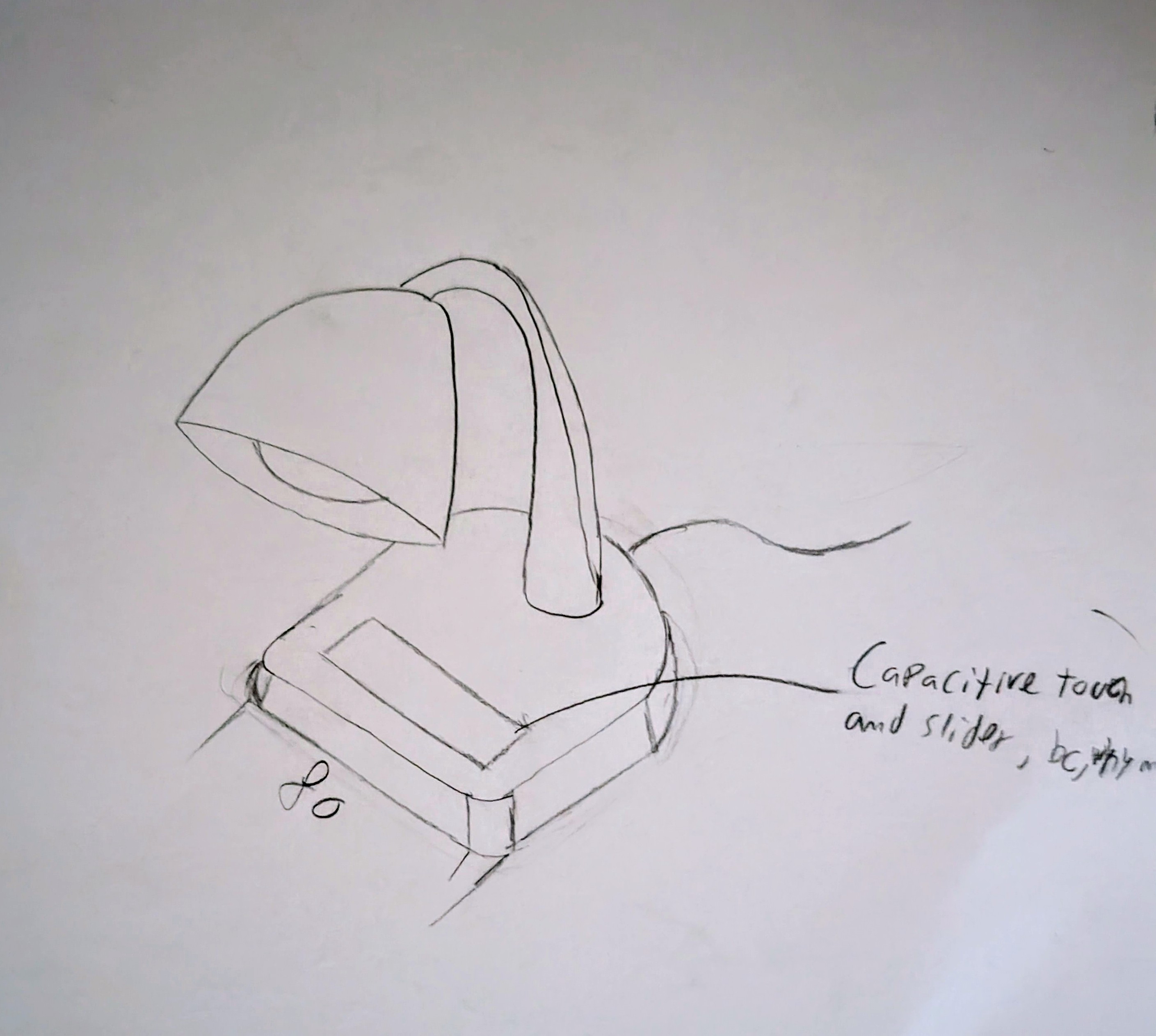
To start the project, I wanted to do a mockup of the design.
I drew the idea I had in mind, which was a simple desk LED light, I also wanted it to have capacitive touch buttons to control the brightness, bc, why not?
 Total time spent: 2h
June 10th: Mockup
Now I had the mockup, and had to start thinking about the components I would need. To start with, I wanted to use espHome, so I would be using an esp32, as in most of my projects. I also wanted a way yo control the brightness, so I would need a mosfet (or led driver) to control the LEDs. Probably a buck PSU for the esp32 will be needed too, and maybe another for the LEDs.
Components I decided to use: - ESP32-C3-MINI-1-H4 - XLG-20-M (ACDC led driver with PWM and 0-10V dimming) - IQS7222A001QNR (capacitive touch controller) - JST XH connector (for the LEDs) - RS-15-24 (24V PSU)
Total time spent: 4h
June 11th: Continue searching for components and starting the schematic
Yesterday I started looking for components, and had to quit early, so I continued today. I also thought of removing the XLG-20-M, and using 2 led drivers, warm and cold, to control the color temperature. I'd use this CWWW implementation: https://esphome.io/components/light/cwww.html Final omponents I decided to use: PCB1 (aluminum PCB for the LEDs): - AL5802-7 (LED driver for the LEDs) - GW JTLPS1.CM-JNKN-XX51-1-150-R33 (cold white LED) - GW JTLPS1.CM-HNKK-XX510-1-150-R33 (warm white LED) - JST XH connector (for the LEDs) PCB2 (main PCB): - ESP32-C3-WROOM-02-H4 - AP63203WU-7 (buck converter for the ESP32) - IQS7222A001QNR (capacitive touch controller) - JST XH connector (for the LEDs) - RS-15-24 (24V PSU) - 6100.3300 (AC C14 connector)
- 6.3mm faston terminal
- SN-02C (crimp jaw for the terminals)
I also found this documentation for capacitive touch buttons: https://ww1.microchip.com/downloads/en/Appnotes/Capacitive-Touch-Sensor-Design-Guide-DS00002934-B.pdf
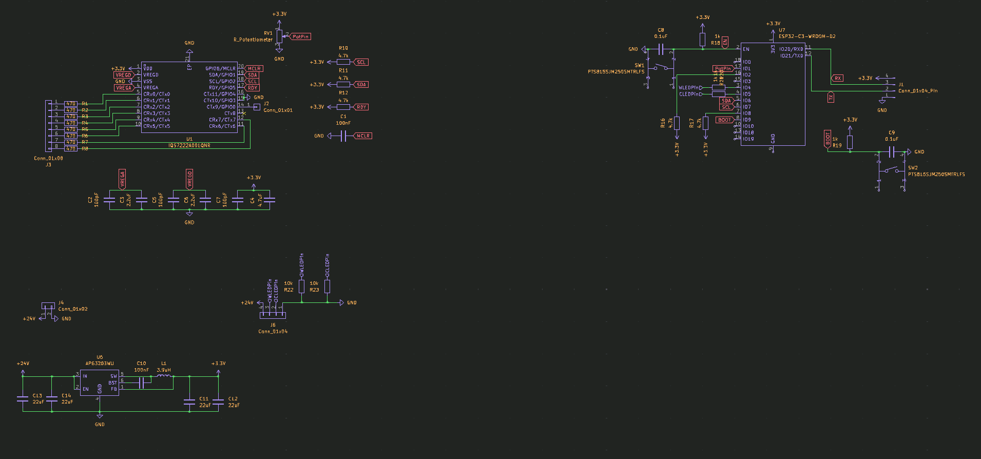
I started designing the schematic, started with the capacitive touch controller. For that I designed a simple footprint for the electrodes.
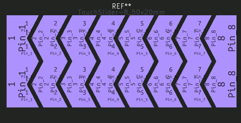
Final capacitive circuit:
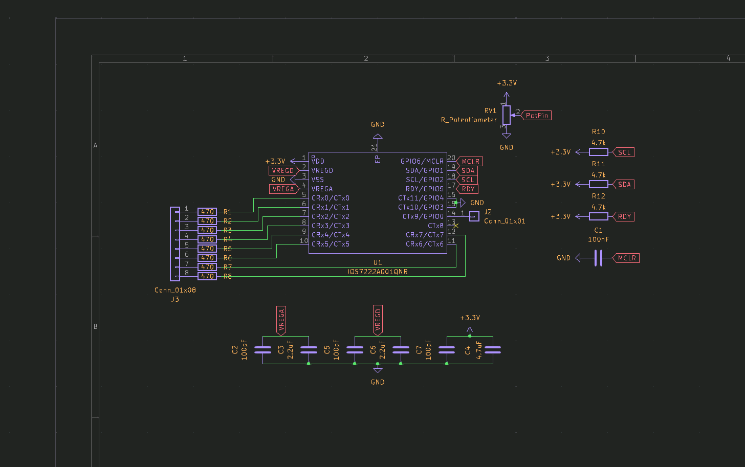
PS: It was my first time designing a capacitive touch circuit, so I hope it works.
Total time spent: 6h
June 12th: Continuing the schematic
Today I continued the schematic, more specifically the ESP32 part. I first designed the esp32 circuit as if it was an esp32-S2, but then I realized it was an ESP32-C3, so I had to change strapping pins i used.
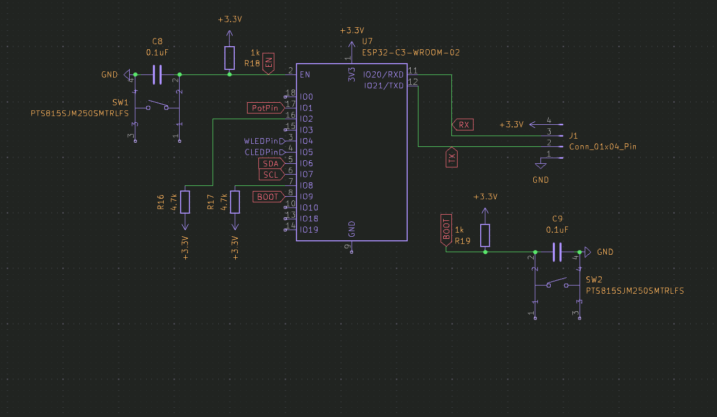
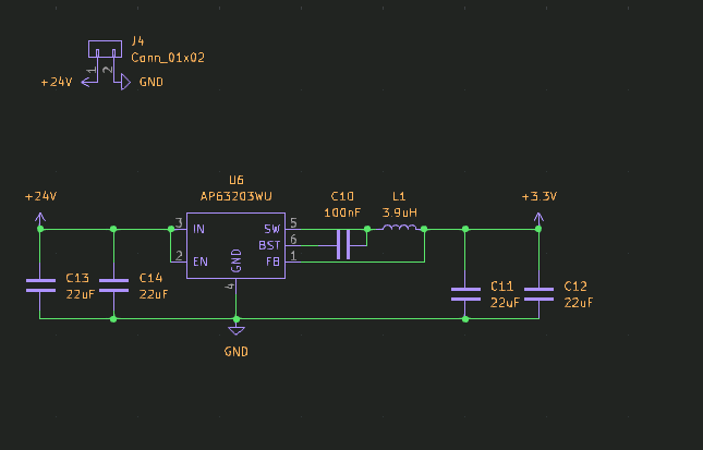
I also added the buck converter, and the power supply connector.
Total time spent: 3h
June 13th: Finishing the schematic
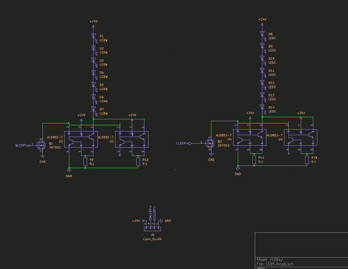
Today I finished the schematic, I added the LED driver and the LEDs. I also added the connectors for the LEDs.
Total time spent: 1.5h
June 14th: PCB design
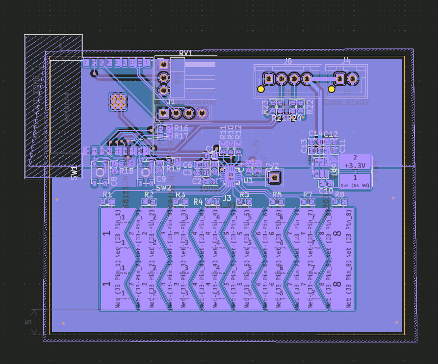
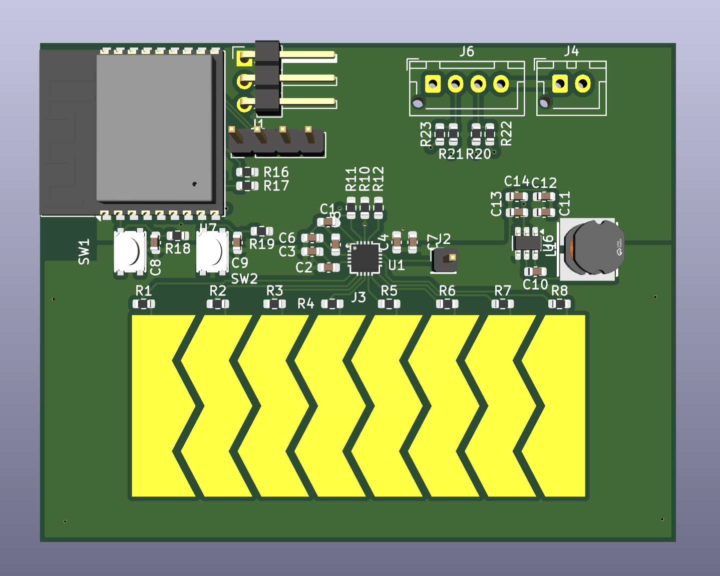
Today I started the PCB design, I first designed the PCB for the capacitive touch controller (Main PCB), as it didn't seem too hard. I used 2 layers with FR4, as it was cheap and easy to work with.
After wiring everything, I finished the pcb. I'm not sure if the electrodes are too close, but I hope it works.
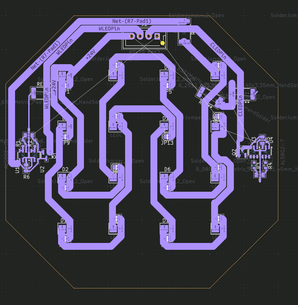
Then I started the PCB for the LEDs. I wanted it to be an Aluminum PCB, as it is the optimal choice for medium to high-power leds, so I think it would be a perfect fit for the LED PCB. Sadly, Aluminum PCBs are one-sided, which was complicated quite a bit the design. I tried for hours to find a way to make it work, but I couldn't find a way to route the PCB without using vias, which is not possible with Aluminum PCBs. So I gave up for the day, and decided to try again tomorrow. This is what I have so far:
Total time spent: 5h
June 15th: Finish PCB design
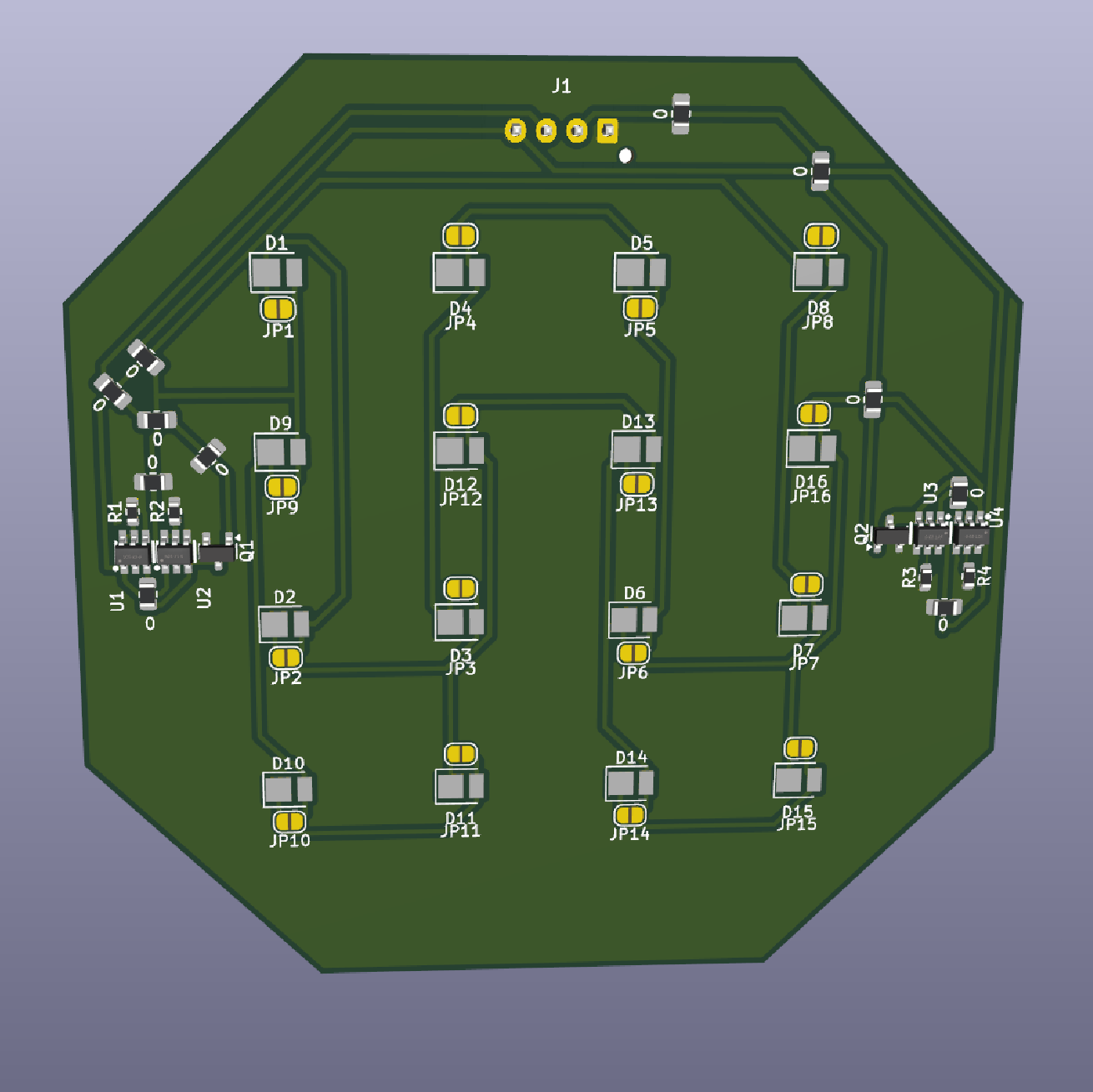
Today I finished the PCB design, I found the perfect a working arrangement!
It took me a while, but thanks to a new set of eyes, I finally managed to route the PCB without using vias.
I decided on using 0 ohm resistors as jumpers to create a virtual 2nd layer. IIRC, I saw this being used in a video from GreatScott, so I thought it was a good idea to try it out.
After quite a bit of work, I finally finished the PCB design!
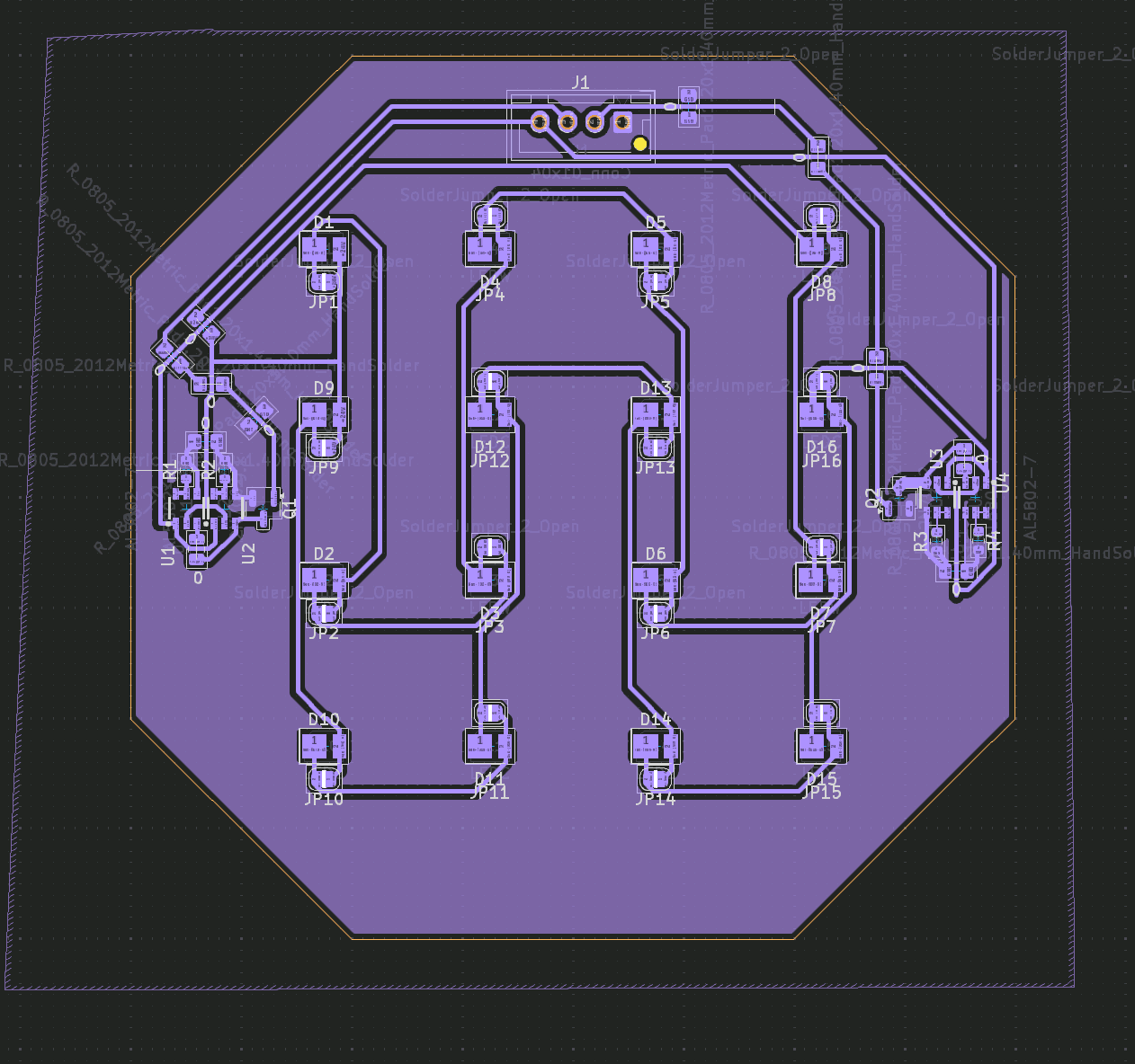
PS: DRC gives quite a few errors bc of the jumpers, but I don't care, as they should work and I don't know how to tell kicad it's a 0-ohm jumper without modifying the schematic.
Total time spent: 6h
June 16th: Start the 3d model
Today I started the 3d model, I wanted to make it simple and base it on the mockup I made at the beginning of the project.
To start with, I searched for a rigid-flexible tube I could use for the top part, as I wanted it to be adjustable. I really didn't know what to search for, so I just searched for Flexible desk lamp tube
on aliexpress, and started hopping from one product to another until I found this one: https://es.aliexpress.com/item/1005007938186623.html The 30cm silver, Outer M10-Outer M10, seems to work for me, so I added it to the BOM.
Now that I've got all the non-printed items, I started designing the 3d model. To start with, I designed the LED part, which is the part that will hold the LEDs and the aluminum PCB. I started with a simple cone, but switched to an octagonal prism with taper angle of 15º, as it was easier to design and looked better.
What I have so far:
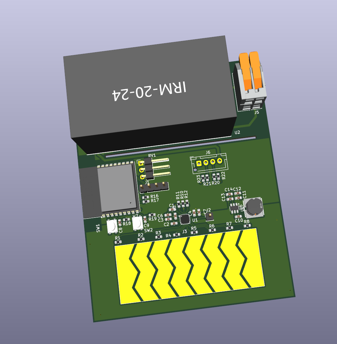
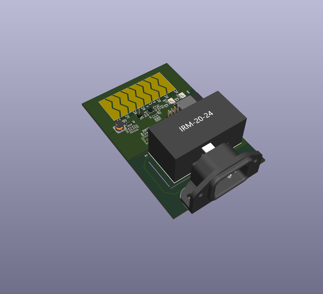
While designing the 3d model, I realized the PSU was quite big, so I searched for a smaller one. I added it to the pcb.
Total time spent: 5h
June 17th: Finish the 3d model and BOM
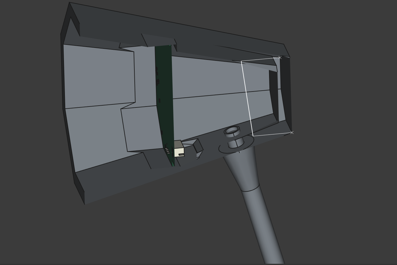
I had the 3d model almost ready, so I just had to do the base, which was qutie simple. But to make it easier, and stronger, I replaced the original C13 connector with a new THT one, this way I don't need spade connectors to connect it to the PCB.
I also added a holder for the LED PCB. I'll use 3d printed clips to hold it in place, probably also a bit of hot glue.
Final result:
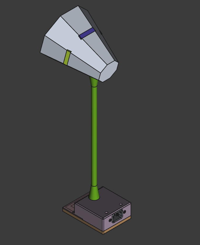
Total time spent: 6h
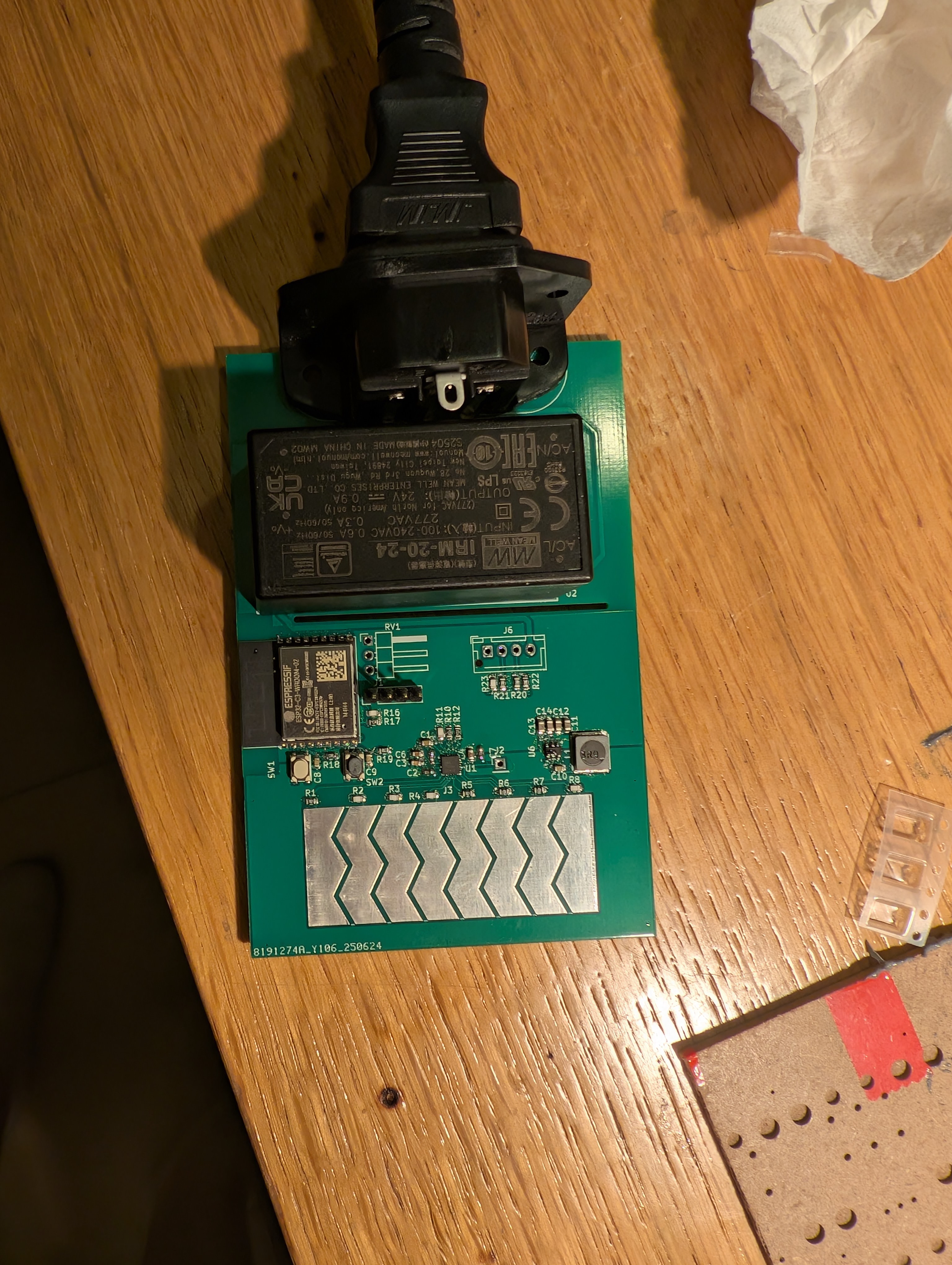
July 30th: Soldering the PCB
Yesterday I recieved the PCBs, so today I started soldering them. Sadly the solder paste I had was expired and a bit dry, so just added some flux to it and hoped for the best. Soldering worked well enough, I haven't yet tested the board. hope it works.
PS: I plugged the power cord, and it didn't blow up!!
Total time spent: 4.5h
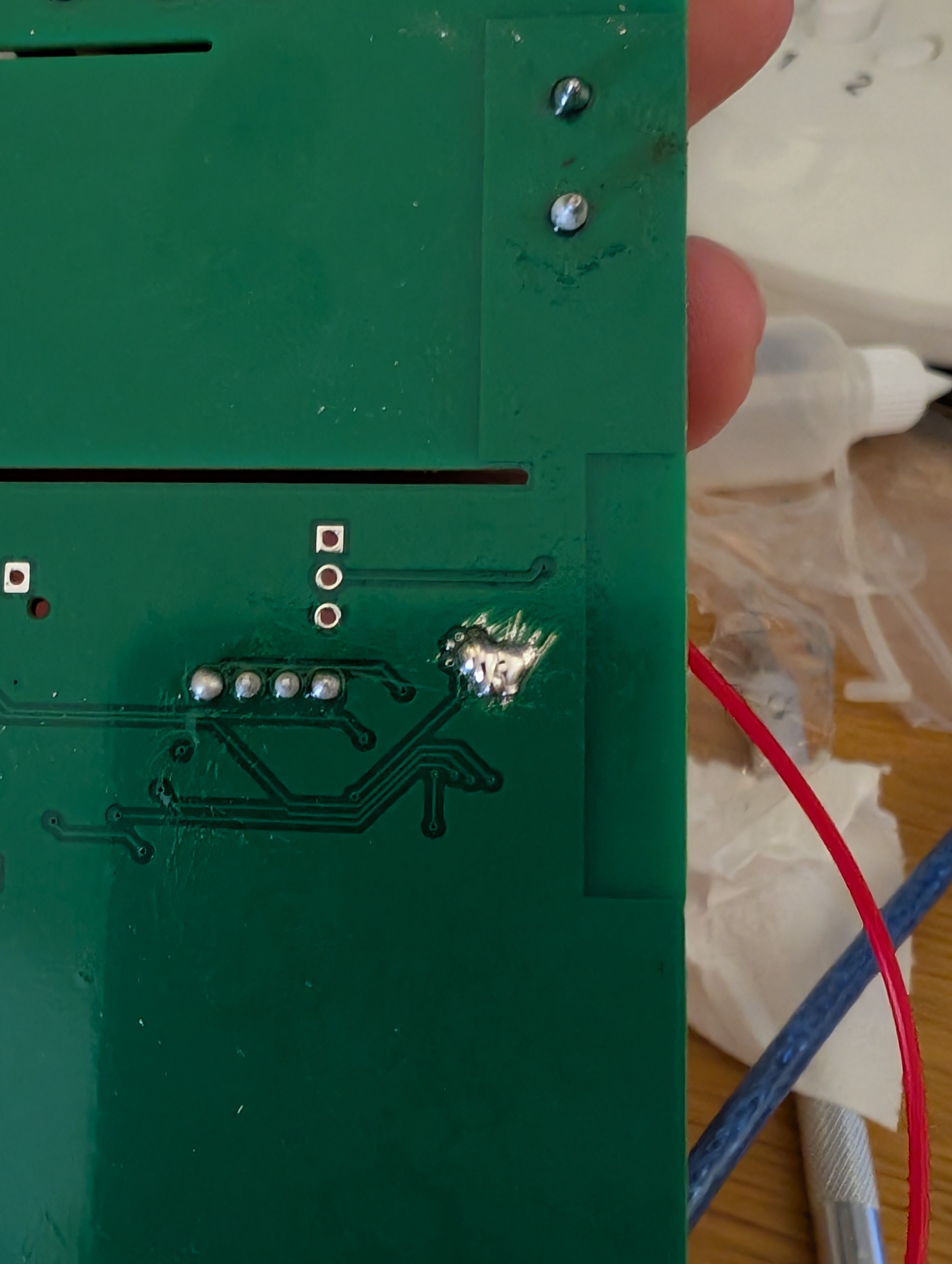
July 31st: Testing the PCB
Today I started programming the ESP32, I used PlatformIO. First, I created the project, and configured the platformio.ini file to use the ESP32-C3 board. It didn't work, and I didn't know why, but luckily I found, after quite a lot of messing around that the PCB had a design error, GND wasn't connected!!. Luckily I was able to fix it relatively easily. I just scratched the back of the PCB and bridged a GND via to the GND fill. Then, the board uploaded, but the code didn't run, and I found out it was because I had set the wrong board. I used an adafruit one, and i should have used a generic one. After changing the board, it worked!
Now I tried to connect the capacitive touch controller, but it didn't work. It wasn't being detected by the ESP32, so I checked the wiring. I even tried soldering to the QFN pins, but it still didn't work. I ended up giving up, as I didn't find any useful information, as it seems like no one has used this controller with an ESP32 before. I think I'll focus on the LEDs first, and then try to get the capacitive touch working (if I can find a way to do it).
Total time spent: 6h
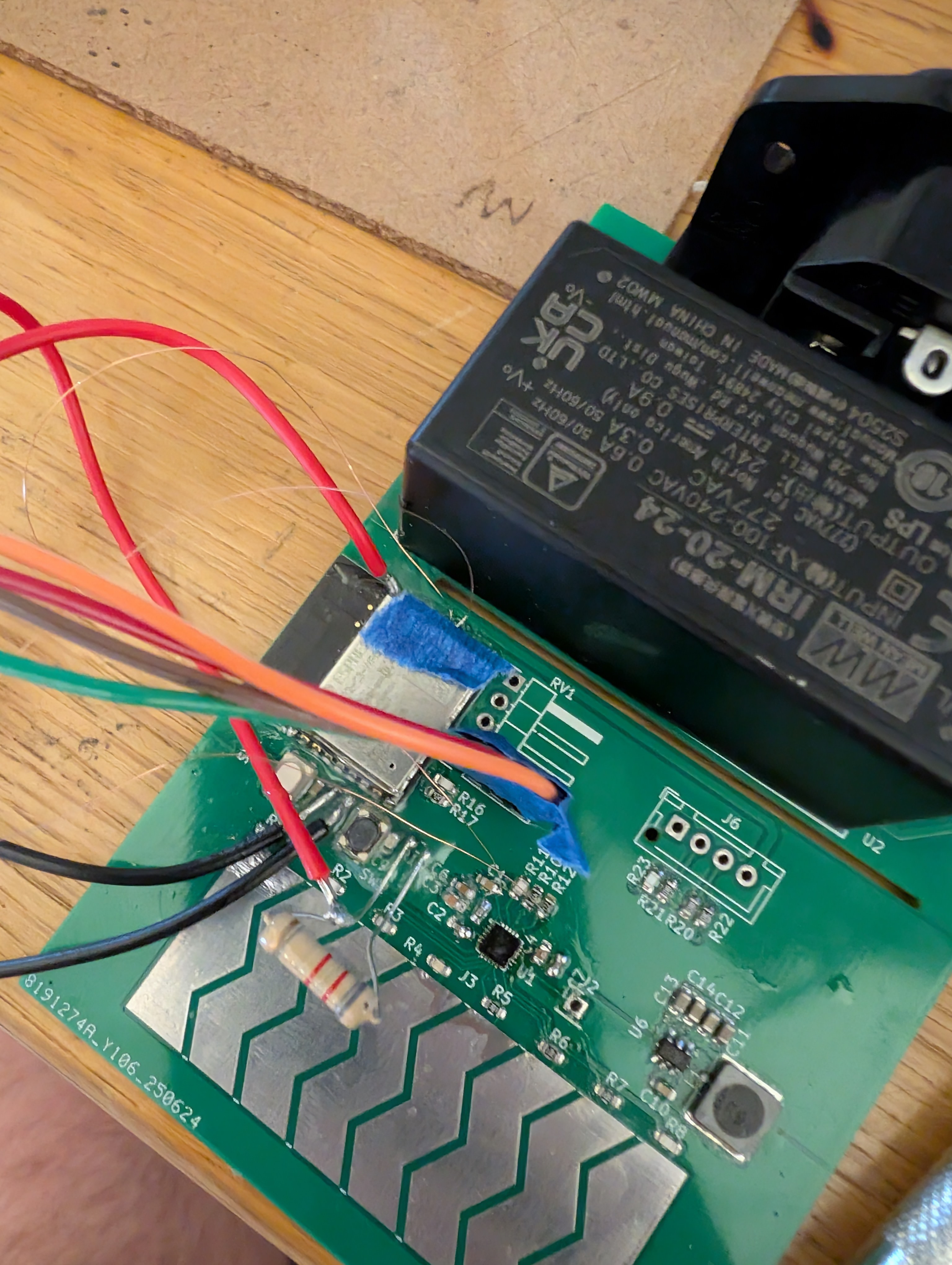
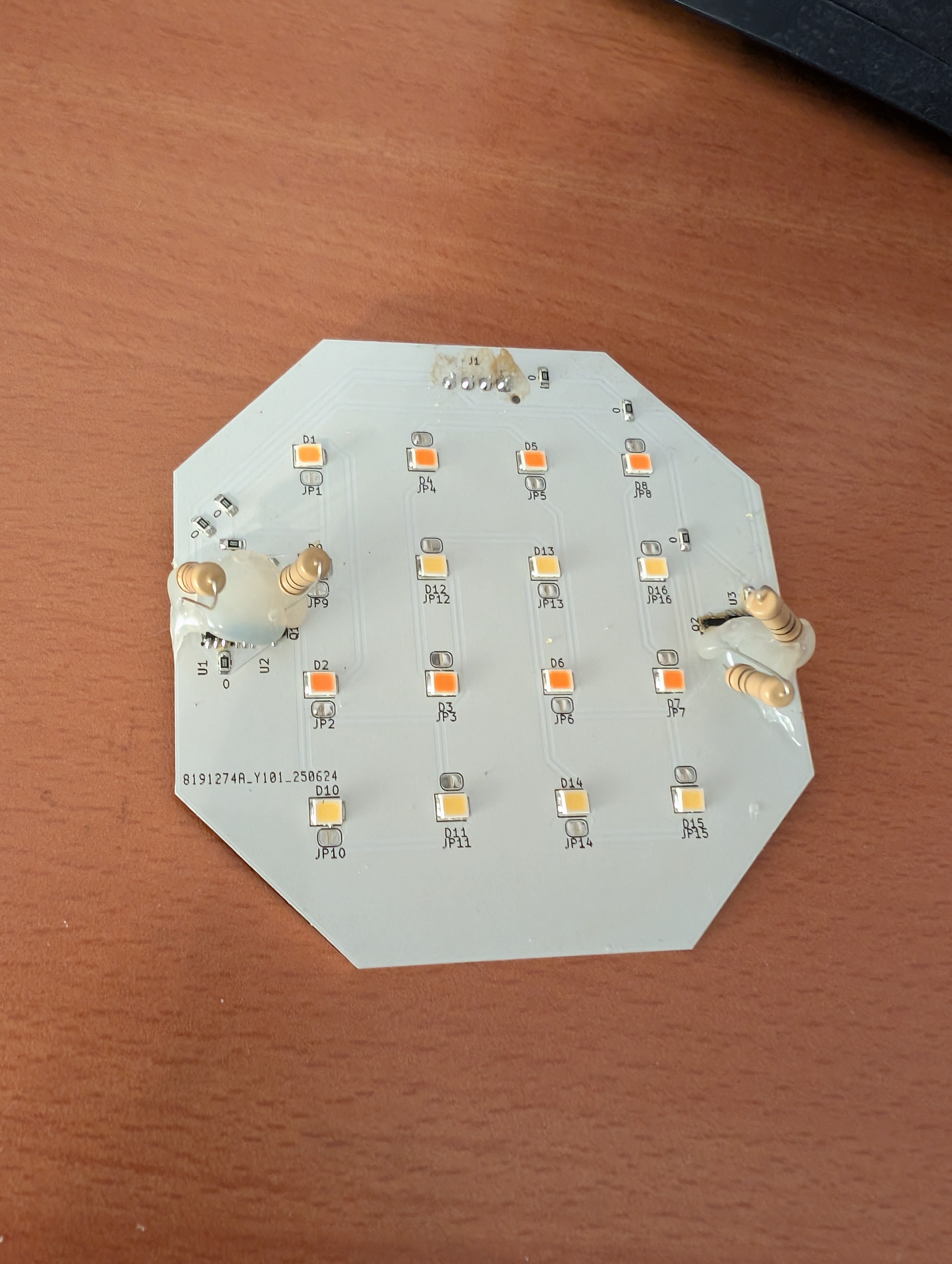
August 3rd: PCB worked!... for a moment
Today I soldered the LED PCB. I placed all the LEDs, led drivers, but I found out I hadn't ordered the led driver resistors, so I had to use some 10Ω tht resistors I had lying around. I soldered them, which was hard, and I broke one pad, but I managed to solder them. I also added hot glue to the pcb so the resistors wouldn't fall off and break more pads. Then I tested the LEDs using some voltage, and they worked! Now I just had to connect the LED PCB to the main PCB, and code ESPHome to control the LEDs. Luckily that was easy. I was able to do it quite quickly, and I was able to control the LEDs using ESPHome. I also added it to my Home Assistant, so I could control it from there. I even got dimming and color temperature working!
Sadly, after a few minutes, the LEDs went full brightness, and the ESP32 stopped responding. I tried resetting it, but it didn't work. Then I used my finger to feel the temperature of the ICs, and the 3.3V buck was burning hot. I had to remove the power, and let it cool down. After a while, I tried again, but with no luck. The ESP32 was fried, and the buck converter was also fried. I think the problem was that the buck wasn't being cooled properly. Luckily the led drivers were fine, and so were the LEDs, so I could just use the light at full brightness.
Total time spent: 5h
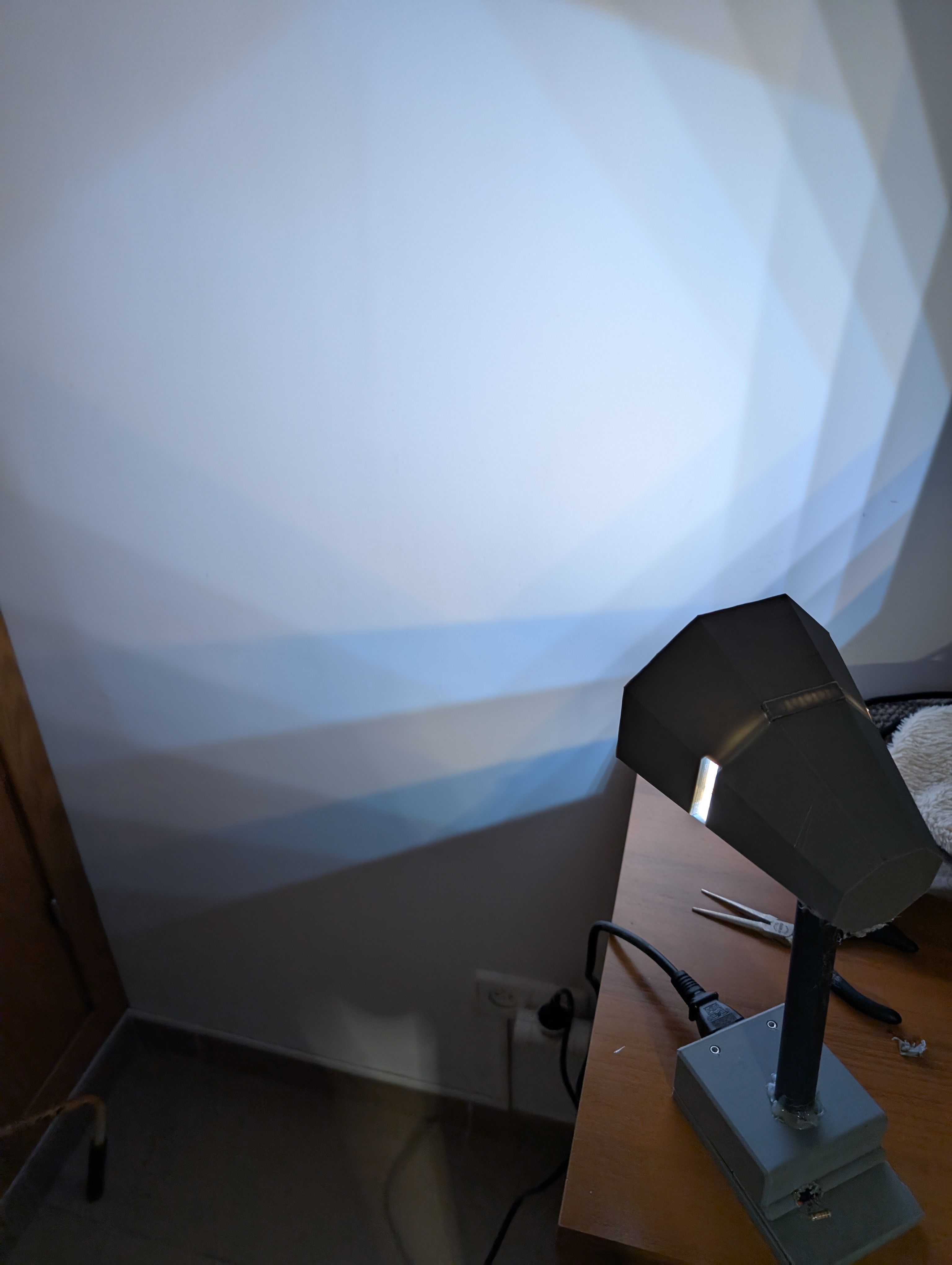
August 4th: Assesmbly of the case
Today, after the disaster yesterday, I decided to assemble the case. I had already printed the parts, so I just had to put them together. Sadly, Aliexpress canceled my order for the flexible tube, so I had to use a regular pvc tube, which I glued with hot glue to the base. I was also unable to use all PCB clips for the LED PCB, as the resistors I used were interfering with the clips, so I just used the top clip which was barely enough to hold the PCB in place. I also added some hot glue, so it wouldn't fall off. Also, by accident, it creates a cool octagonal pattern on the wall, which I really like.
Total time spent: 4h