
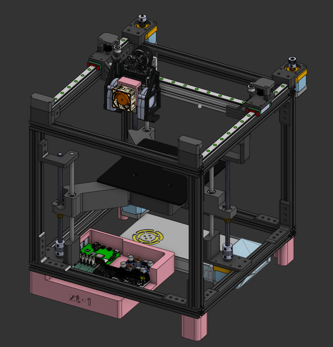
XT-1
Modular CoreXY 3D Printer with a focus on repairability.
Total time: 104 hours
FOR REVIEWERS
If you haven't already, read this document. It outlines the differences between the CAD model and the theoretical real-life build. As you can guess, the CAD model is based on correct schematics (and placeholder CAD models from the internet don't always confine themselves to those measurements). I display all the crucial differences in this document, so I highly suggest you read it first.
Checklist
Pre-Design
Research
Part Picking
Design
T-Plug
- [x] Female Connector
- [x] Male Connector
Toolhead (note: excl. part cooling fans as they're modules)
- [x] Hotend
- [x] Extruder
- [x] Electronics
Gantry
Bed
Base
- [x] Base Extrusions
Modules
- [x] 5015 Part Cooling Fan
Motherboard
- [x] Schematic
- [x] PCB
Extra Features I Want
Belt Tensioner
Table Of Contents (by Date)
- 2025-07-15
- 2025-07-16
- 2025-07-17
- 2025-07-18
- 2025-07-19
- 2025-07-20
- 2025-07-21
- 2025-07-22
- 2025-07-23
- 2025-07-24/25
- 2025-07-26
- 2025-07-27
- 2025-07-28/29
2025-07-15 - Research
I've been researching today about 3D printer parts and brainstorming all the logistics behind this modular system.
Estimated time: 4 hours
Designing Factors
- I want my printer to be easily user-repairable without any issues (taking inspiration from Framework devices)
- Single/two common screw heads used throughout the build (I'm thinking of Torx T10 or T5) **(NOTE FROM THE FUTURE: Turns out it's hard to source Torx screws! I'm going with Philips/Hex heads)
- Attempting to do a heated bed
- Controlled via a socketed Pi CM3/CM4 (Klipper)
- SUPER EASY TO DISASSEMBLE!
- A triple module bay on the toolhead which can be hotswapped while the printer is on (for e.g. filament sensor, RGB, resonance tester, camera, laser cutter :3), using pogo pins and a dovetail system
Part Ideas
Base
- As suggested by Evan Le, I'm going with 2020 T-shape Aluminium Extrusions
- MGN12H or MGN9H rails
- CoreXY gantry
Electronics Ideas
Internals
- Socketed Pi CM3/CM4 on a custom daughterboard
- Socketed RP2040-based (custom?) motherboard
- TMC2209 Steppers
- Mean Well LRS-350-24 PSU
Toolhead
- CR-Touch
- Lancer Melt Zone Long Hotend
- Nema 17 Steppers
- 3 Dovetail Bays for fans & expansions
2025-07-16 - More research & PCB design
Estimated time: 3 hours
On Pi Compute Modules
For designing a motherboard with the Pi 4, I'll need to solder Hirose DF40C-100DS-0.4v connectors, which are SMD.
Designing the PCB (and failing)
I got about this much done in terms of an Ethernet connection (MagJack) before calling quits. I'm now deciding to run a regular Raspberry Pi 4 and use a stock motherboard such as the BTT SKR MINI.
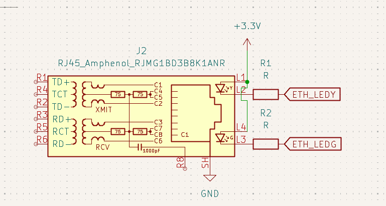
Figure 1 - After hours of reading datasheets, all I could make was this.
2025-07-17 - Starting PCB design
Estimated time: 5 hours
The Dovetail Plug system
(also known as the tail plug system 😬😬😬, i'll be shortening it to t-plug from here on out)
Here is the system for swappable toolhead attachments. I've decided on these main points:
- The CR-Touch will NOT use the attachment system as it requires multiple grounds and for the Z stepper to be on the same MCU (not happening)
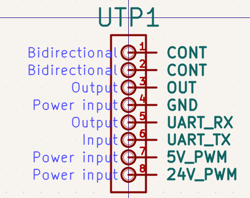
- The 5V and 24V PWM inputs will be turned on as soon as both CONT pins are connected (in the event of a connection)
- One UART bus will be connected for the center module (the Pi Pico only has two UART buses and one needs to be used to connect to the Linux Pi)
I took the time to figure out KiCad and make the necessary symbols and footprints for the t-plug.
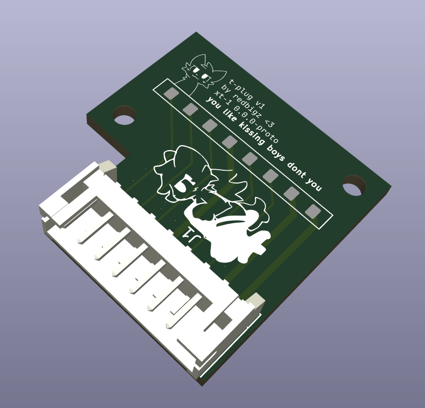
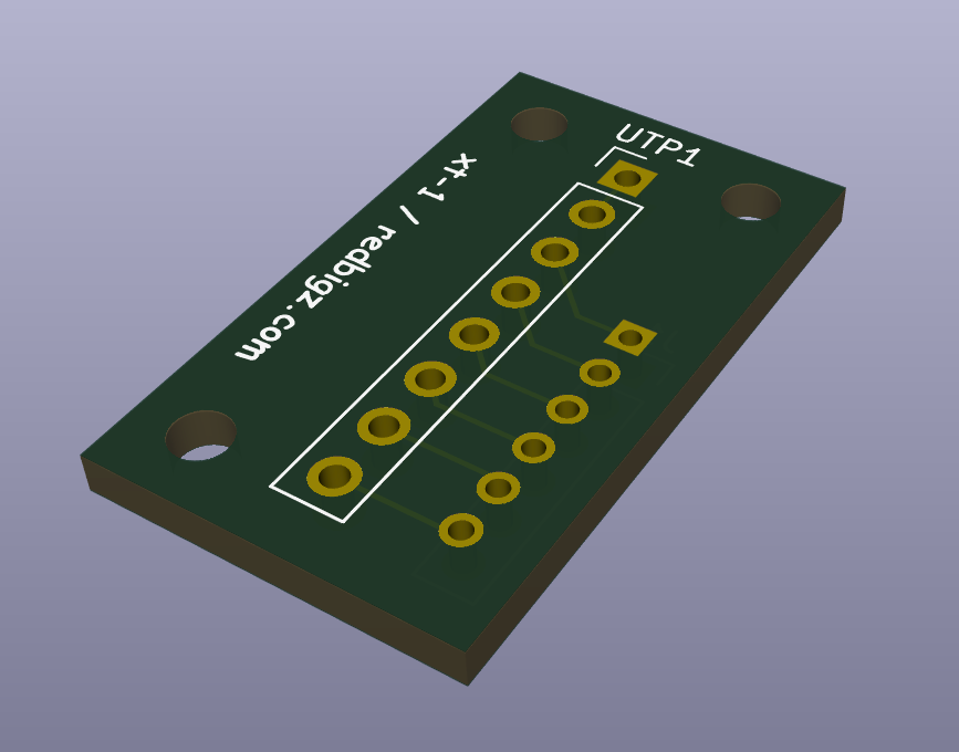
Here is the female PCB, using a JST-PH to communicate with the extruder board:
look at my princess isnt she bootiful
2025-07-18 - CAD Designing and fixes
Estimated time: 6 hours
Plug Design
i've got the thing in OnShape now, and designed a dovetail system for keeping the pogo pins in place.
Base Design
Fixes
Shorting avoidance on the T-plug
I moved ground away from the powered pads to avoid pogo pins shorting due to proximity when sliding. I also changed the pad size of the female receptacle to avoid such proximity (as the pins are 0.9mm and the gap was 0.5mm):

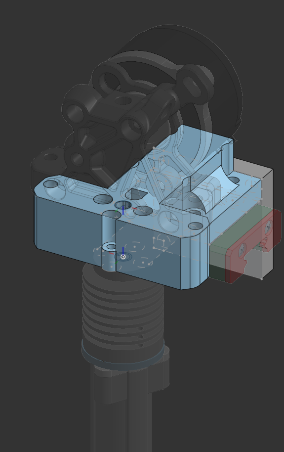
2025-07-19 - Toolhead
Estimated time: 8 hours
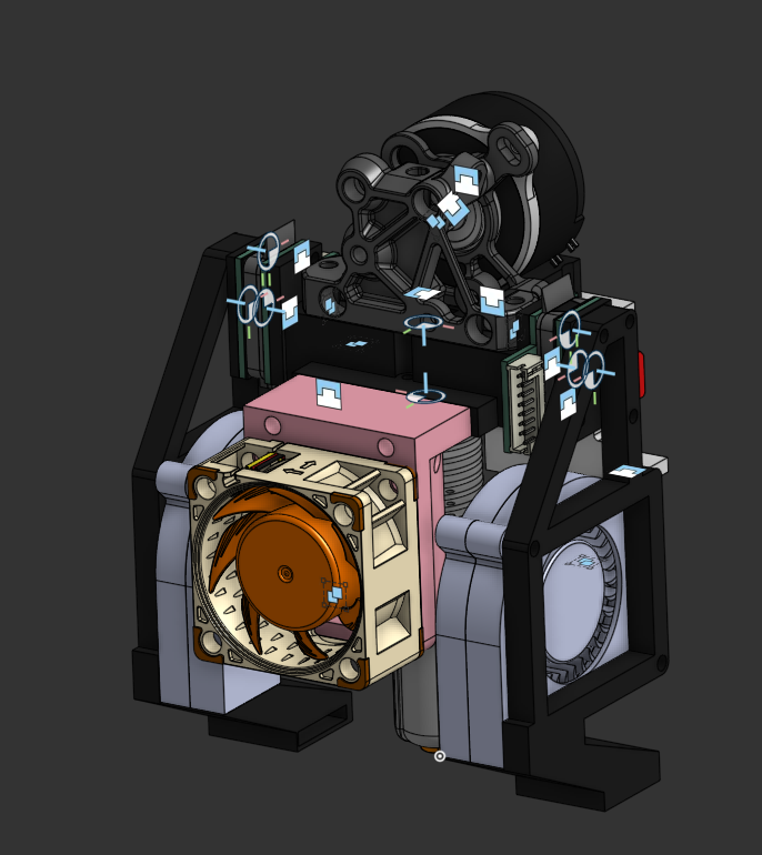
I'm pretty tired so I'll cut to the chase here. I made about 70% of the toolhead, and the only things left are the electronics and fans.
Using a ProtoXtruder for the extruder, with a Nema 14 36mm Round Pancake motor (10T gear)
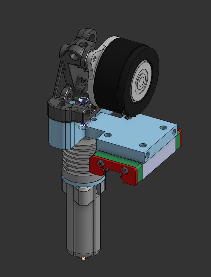
UPDATE: Fixed some heights to make it stronger:
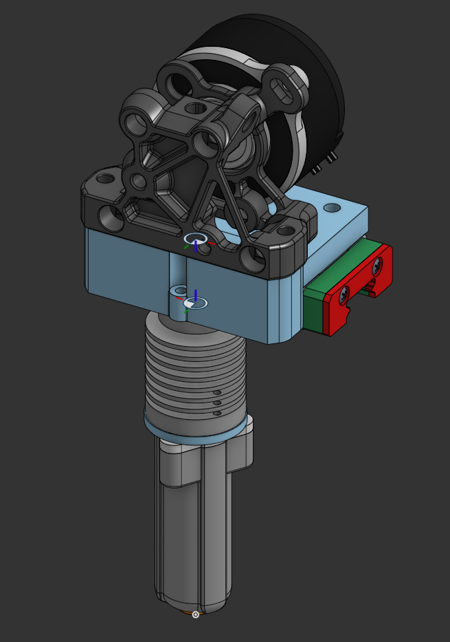
2025-07-20 - More Toolhead
Estimated time: 7 hours
Finished* Toolhead
I've added:
- a 4010 fan (Noctua)
- a belt holder (which doubles as a CR-Touch mount)
- two t-plug bays (I know I said three but there isn't much of a use with three considering the CR-Touch isn't a module)
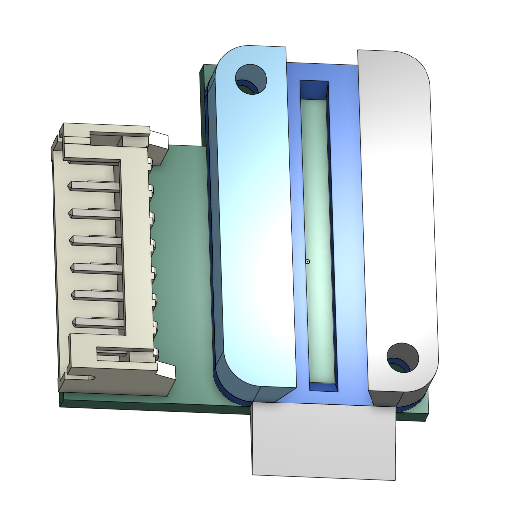
Speaking of which, here is the male t-plug connector:
There's just enough clearance for the connection to the female bay (1.5mm) :3
2025-07-21 - Fan Ducts! (was pretty unproductive)
Estimated time: 5 hours
Today was pretty unproductive. I only managed to get two 5015 fan modules done. Due to the sliding mechanism, the fan module won't slide in unless the fans are screwed in after the frame is slid in.
You gotta admit it looks cool though:
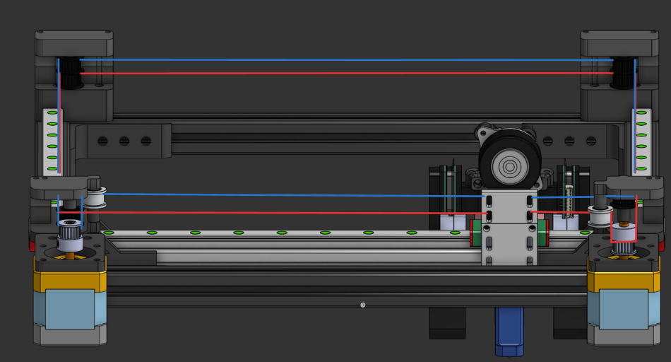
2025-07-22 - Gantry
Estimated time: 6 hours
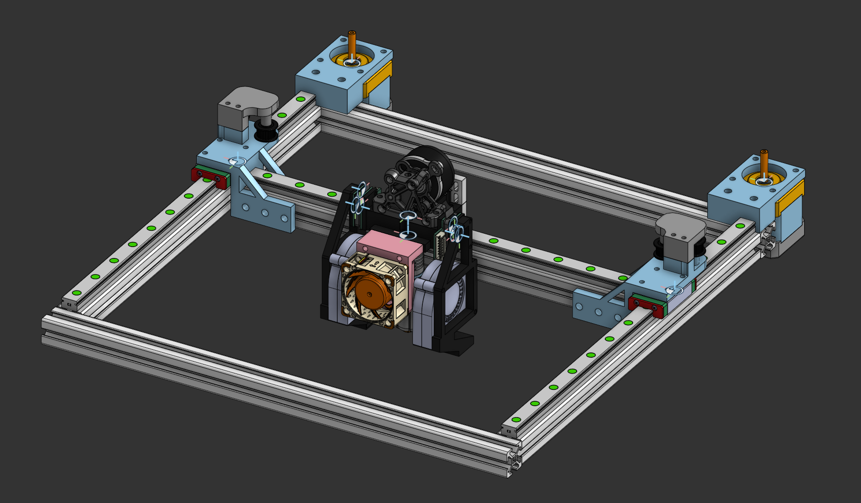
I got a really productive session in CAD today. I've got the toolhead set up on a 360x360 gantry, along with the motor mounts and X axis idlers.
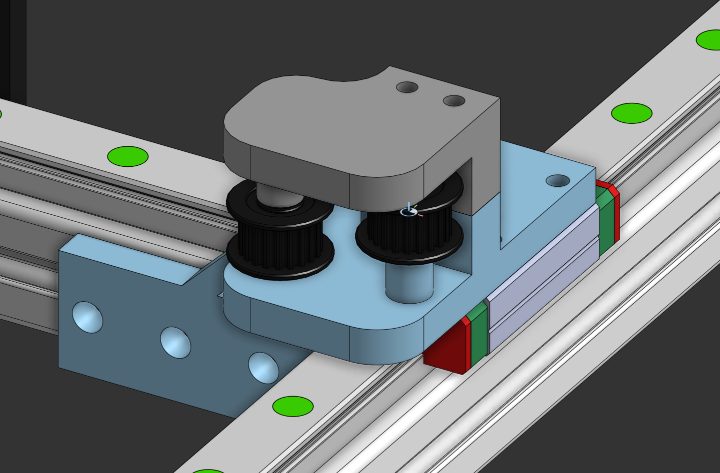
Here's the dual-idler design I came up with (took some inspiration from other CoreXY printers):
I'm basing my belt setup based on this image found in the Anicept Vex CoreXY guide in Highway:
2025-07-23 - Gantry & (Supplementary) Motherboard
Estimated time: 8 hours
I'm pretty tired (again), so I'll just recount what I did.
I finished my gantry in its entirety:
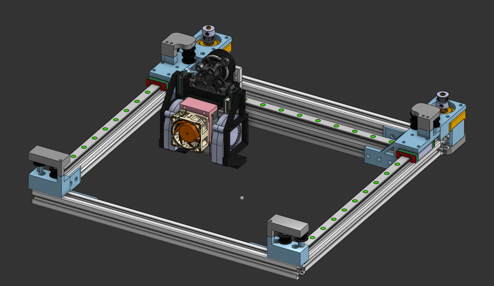
I made custom mounts for all the idlers, and worked out a belt path that barely works. I'll tweak it while building the thing, since I'm starting to run out of time before Highway ends. I've worked out a gantry area of about 190x180 for the toolhead.
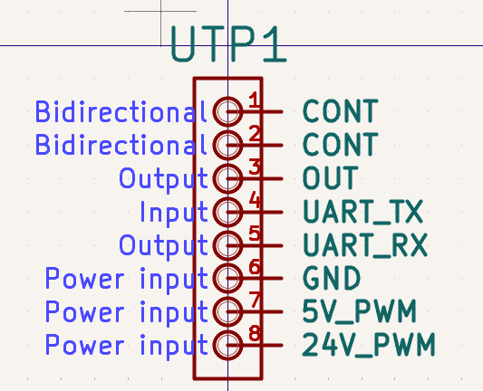
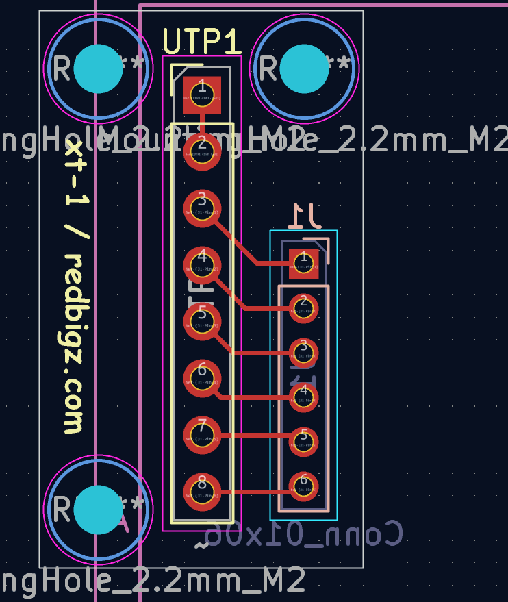
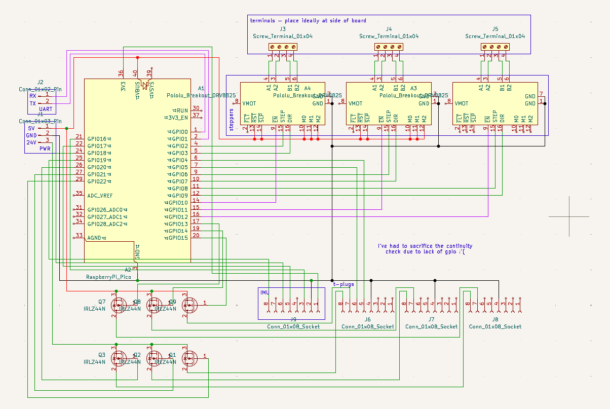
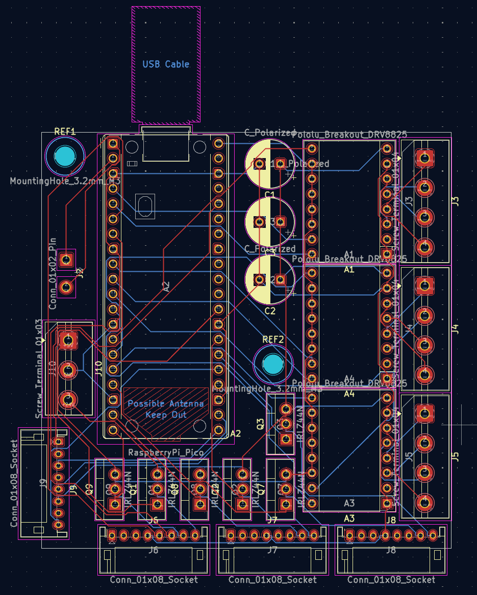
Also, I've started work on a supplementary motherboard (yep, this lil guy has two moms!). It holds three limited ports for the t-plug system (lacking CONT due to a gpio shortage), with one having access to the secondary UART bus. Here's the finished schematic:
2025-07-24/25 - Bed & Supplementary Motherboard
Estimated time: 20 hours
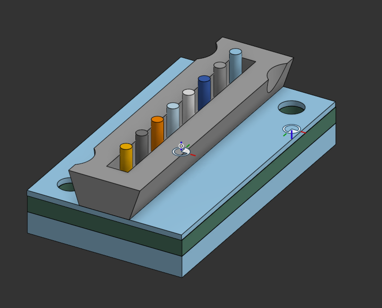
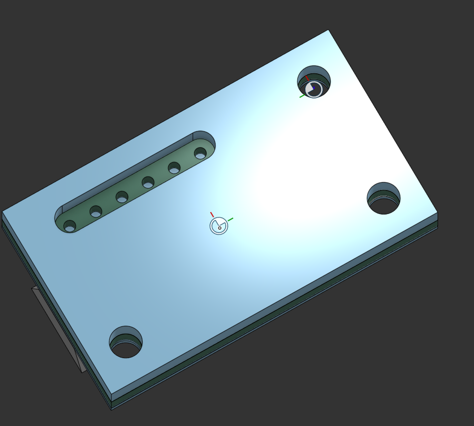
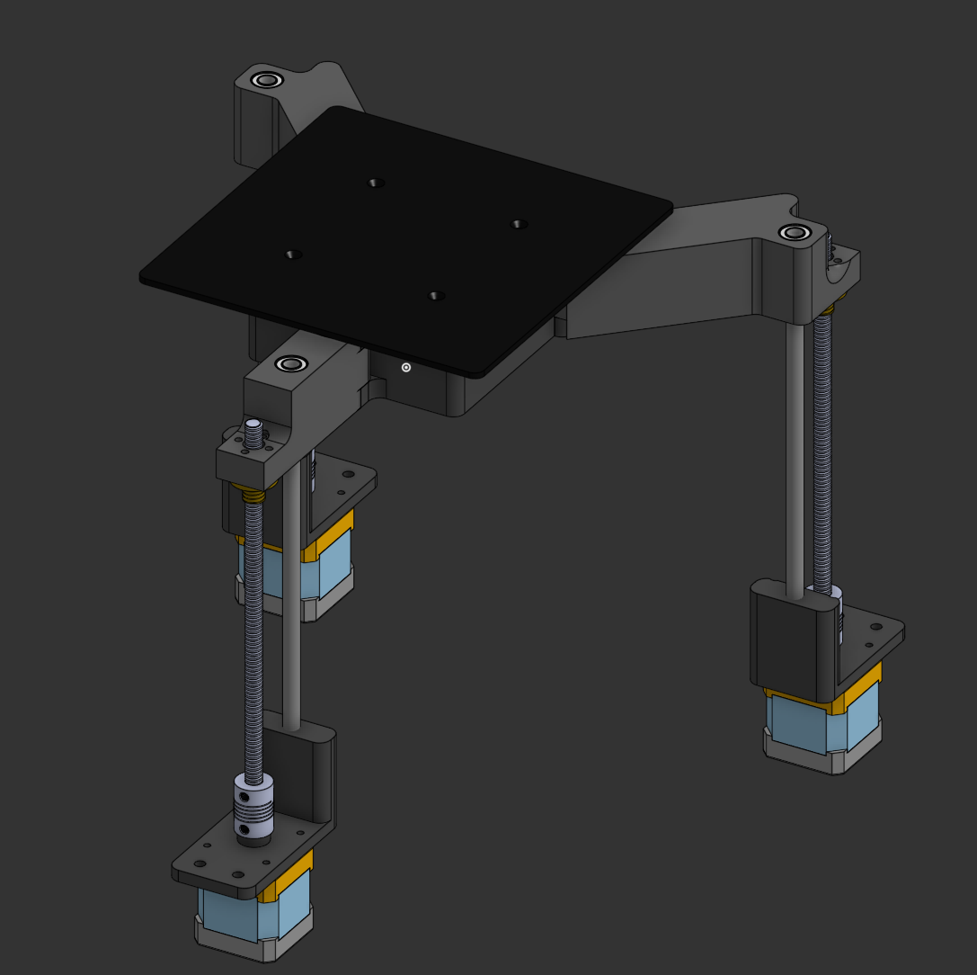
Bed
I've considered using linear rods with LM8UU bearings (the small ones), along with lead screws. I've decided to not use kinematic mounting as it'll add time to a project where not a lot of time is left to submit. I'm using a hotplate from the Lerdge iX cantilever printer as it fits my print size.
Here's the bed:
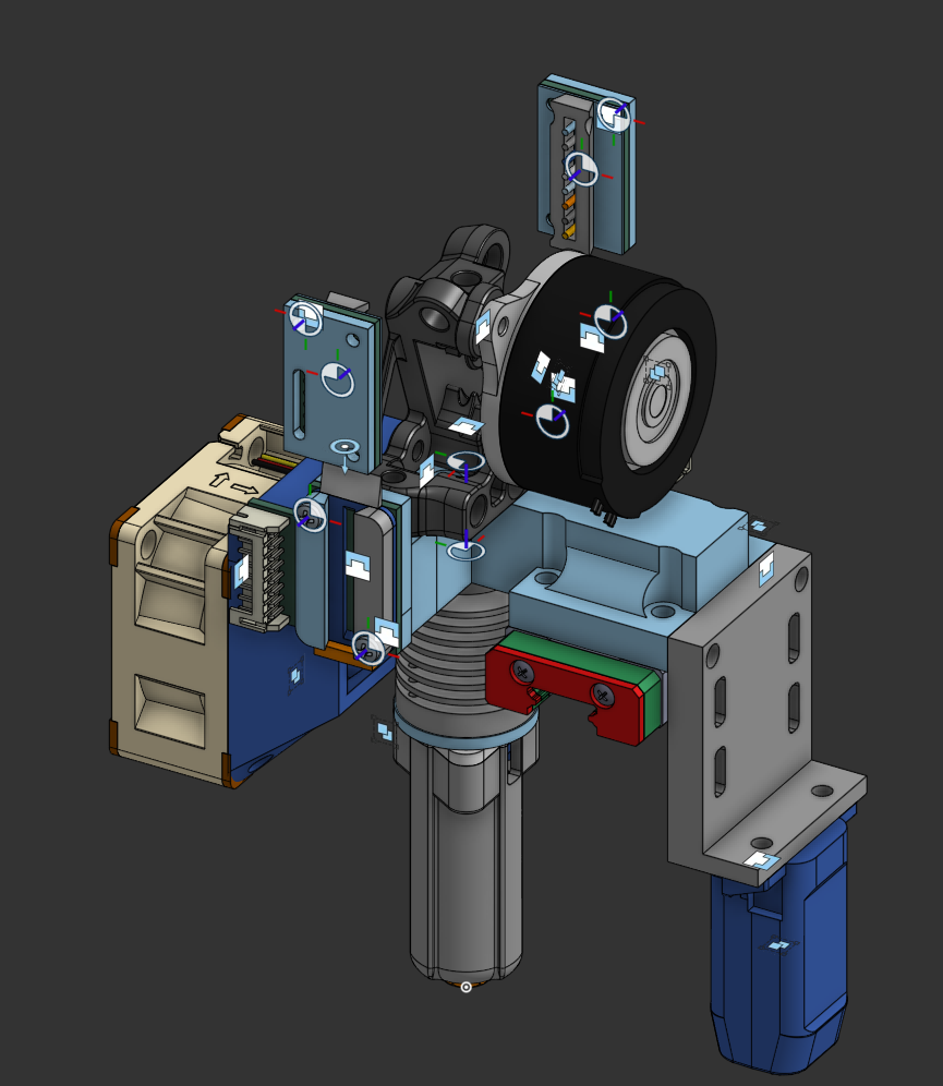
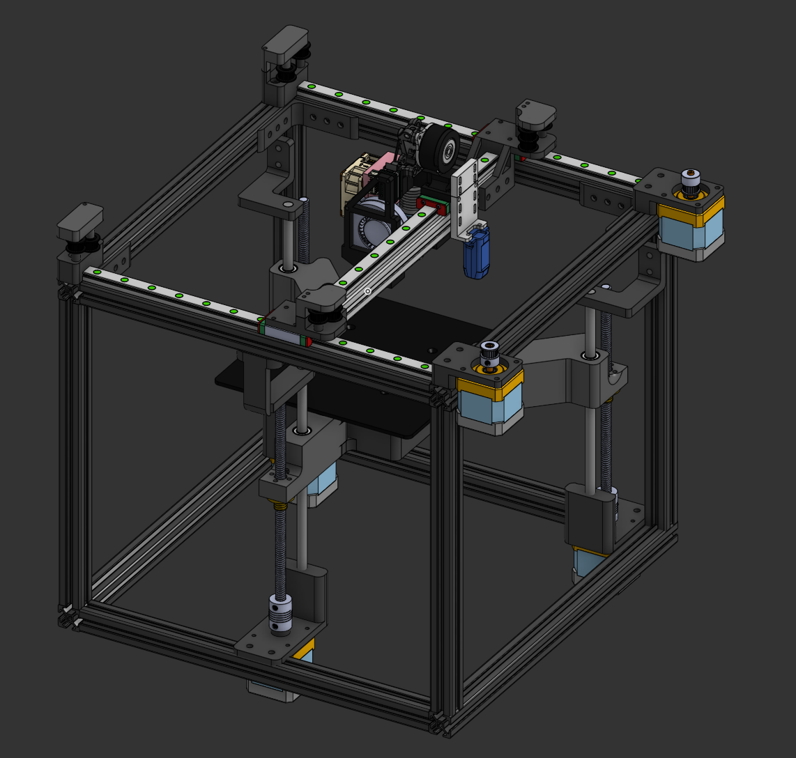
I've also taken the time to assemble the bed and gantry into a full assembly:
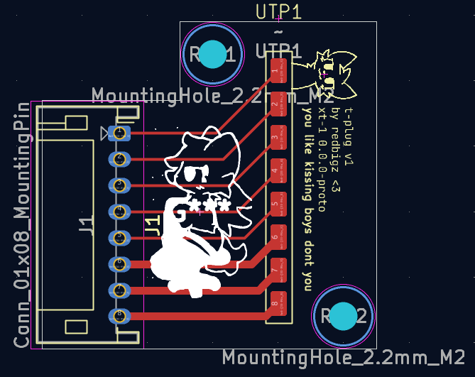
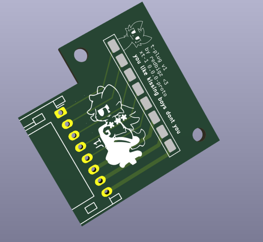
I've also turned the motherboard schematic into a PCB (with a little help from freerouting :3):
2025-07-26 - Electronics and fixes
Estimated time: 12 hours
Fixes
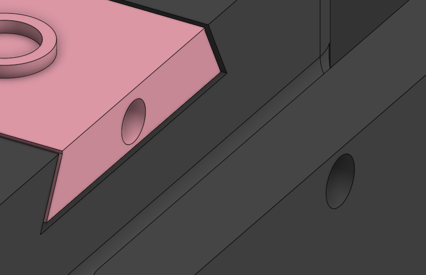
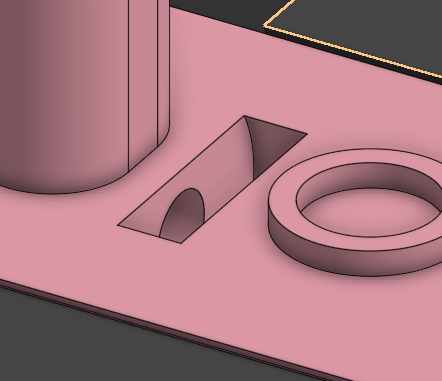
T-Plug Receptacles
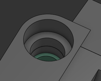
I fixed a collision issue with screws on the t-plug receptacles colliding with the male plug. I fixed this by adding an indent for pan screws.
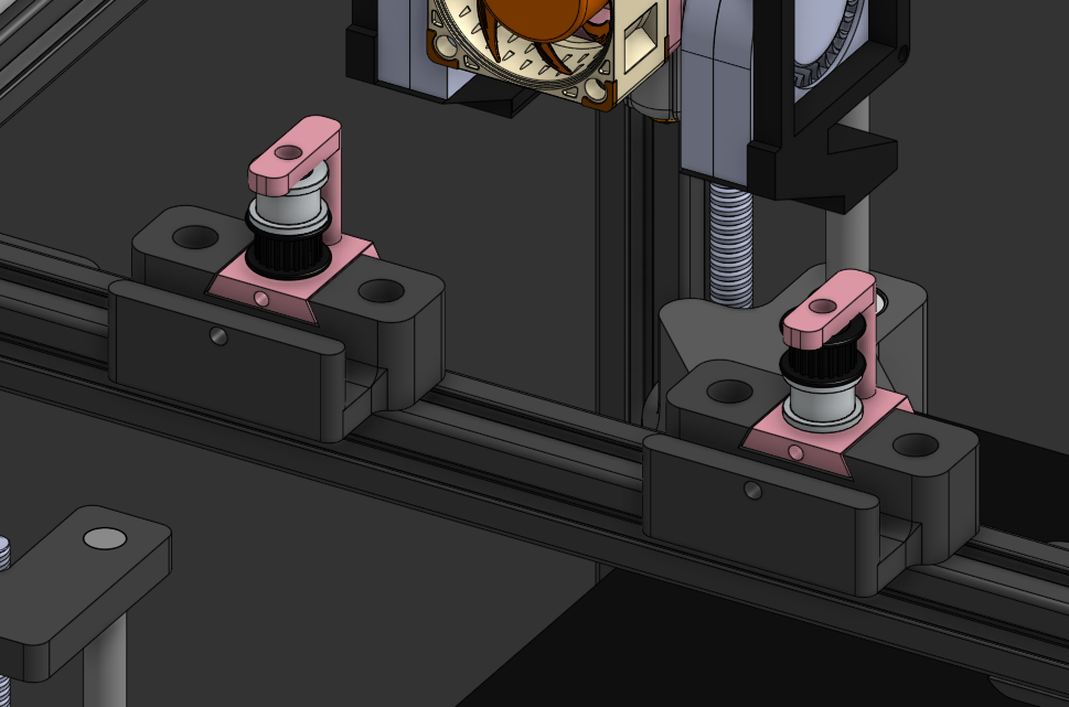
Gantry
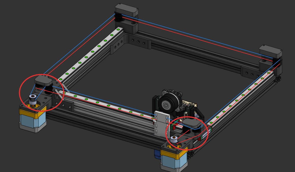
When working on my to-fix list, I noticed that:
- my gantry was fairly uneven
- nothing was perpendicular, so when the carriage moves the belt tension will change (leading to snapping or stretching).
You can see these issues prevalent here:
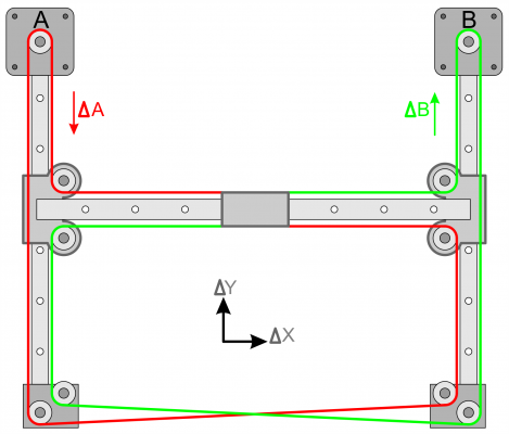
As you can see in this diagram by Mark Rehorst, the critical CoreXY components need to be perpendicular:

Original Caption: UMMD's coreXY mechanism. All the pulleys are stacked, and belt segments A-H are parallel to the guide rails.
I mitigated this by redesigning the gantry correctly:
Additions
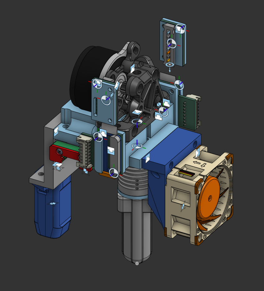
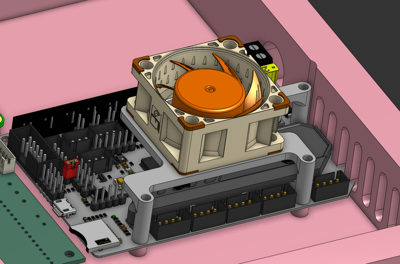
Electronics
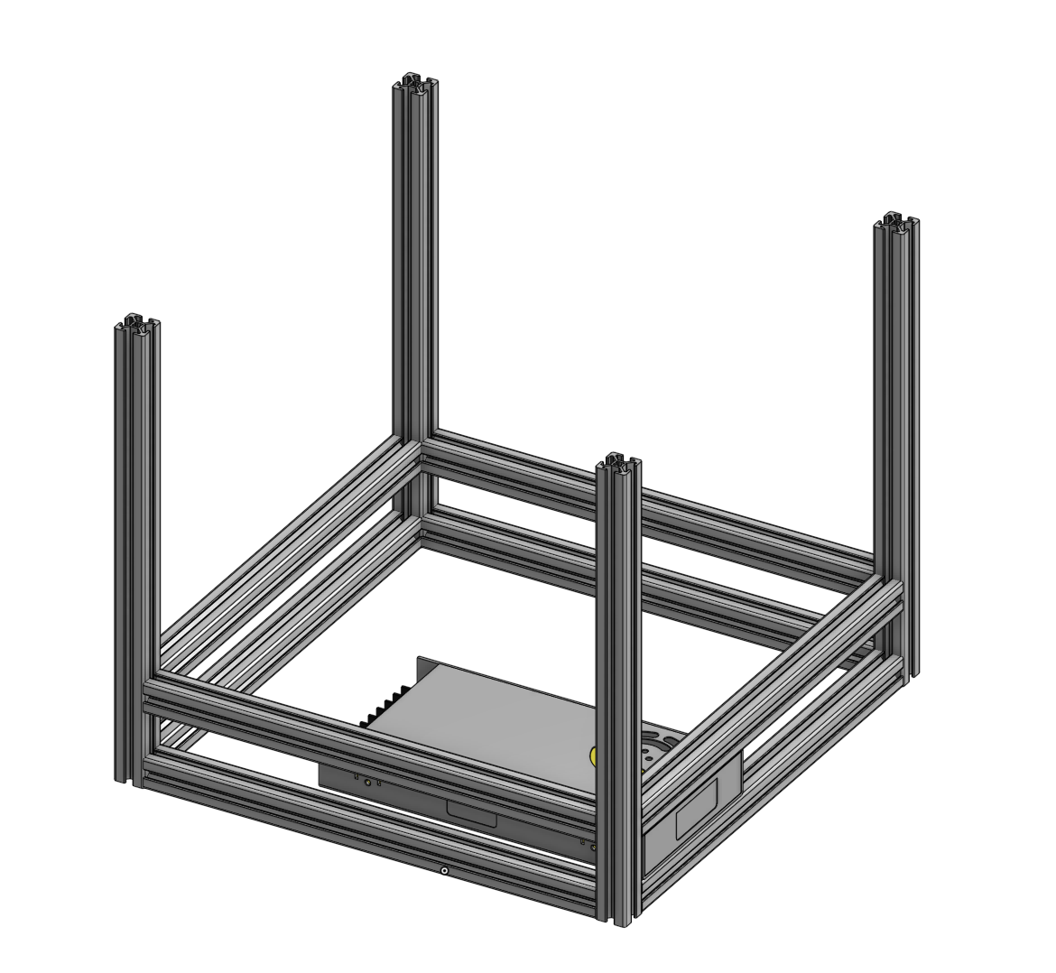
On one of my feet, I've added a compartment holding my Raspberry Pi, SKR, and Supplementary Motherboard:
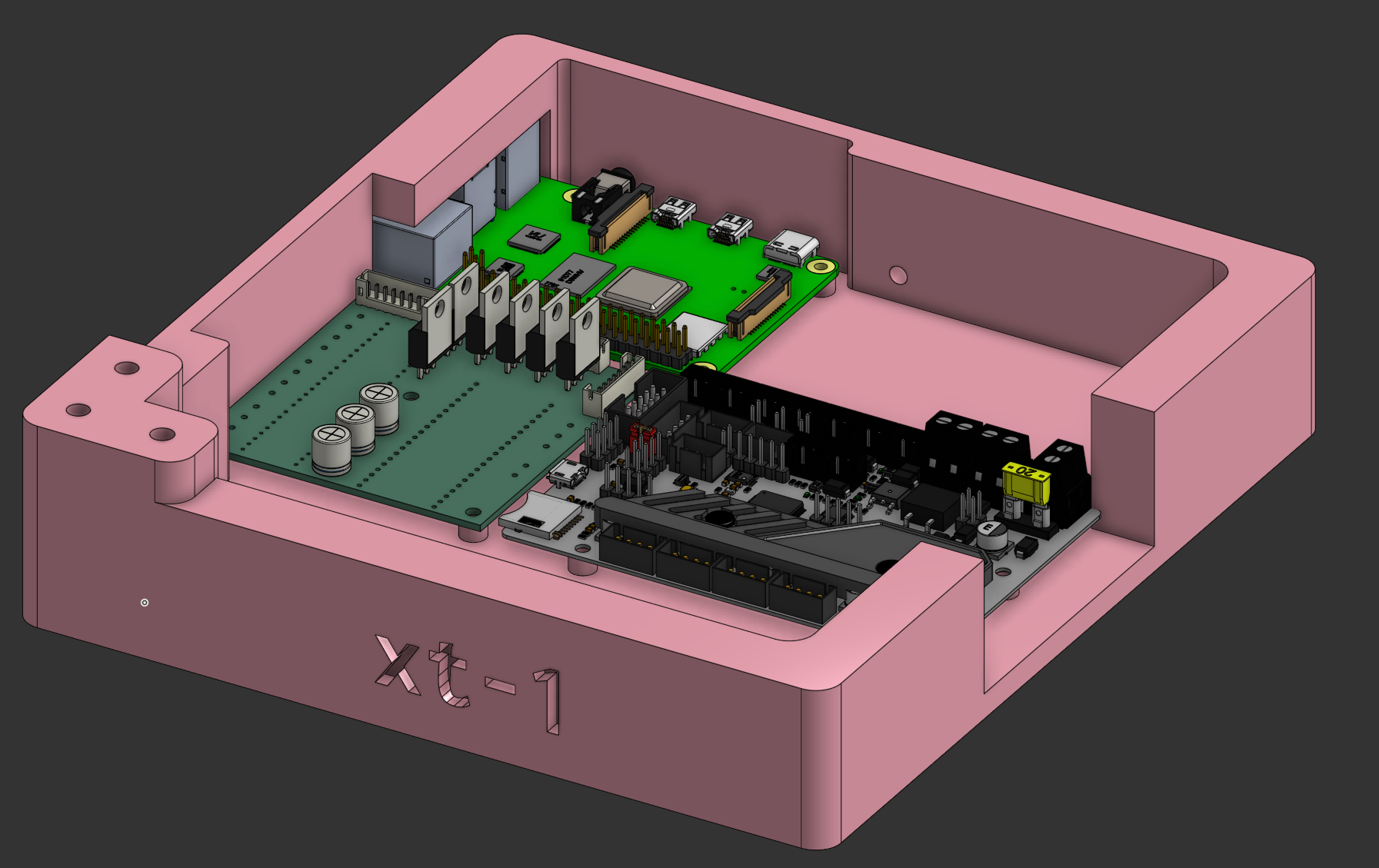
I've also added a singular screw mount for holding the PSU. It's not intended to be secured, but just to position the PSU (at least for now).
You can also see in the first photo that I'm using a PSU enclosure. You can find the model and its author here (thanks pmichaud!).
Full Screenshot
Here's the final build (at least until I make the belt tensioner):
2025-07-27 Minor Fixes & Additions
Estimated time: 9 hours
Belt Tensioner
I've finally implemented a belt tensioner system (although somewhat jank).
It uses a dovetail system with a bolt and nut holding it in place.
Due to a possible collision in the tensioner with the belt, I've opted to add smooth idlers to the opposite belt being tensioned (as seen in the first photo). However, this causes the other belt to be tensioned as well - offset by the diameter of the inner part of the pulley. Having two tensioners allows the user to counteract this effect.
Electronics Lid & Mobo Fan Mod
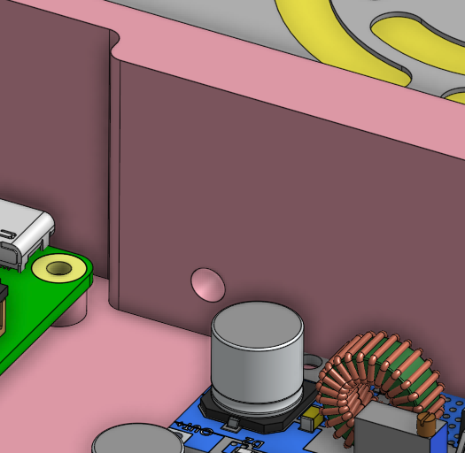
Hi! For this segment I'm utilising this fan mod designed for a VORON V0.1 printer. Thanks 3DMegoldasok!
I've firstly added a lid for the electronics box, secured with three M3 screws. There are two cutouts, one for a fan and one for the main stepper motor.
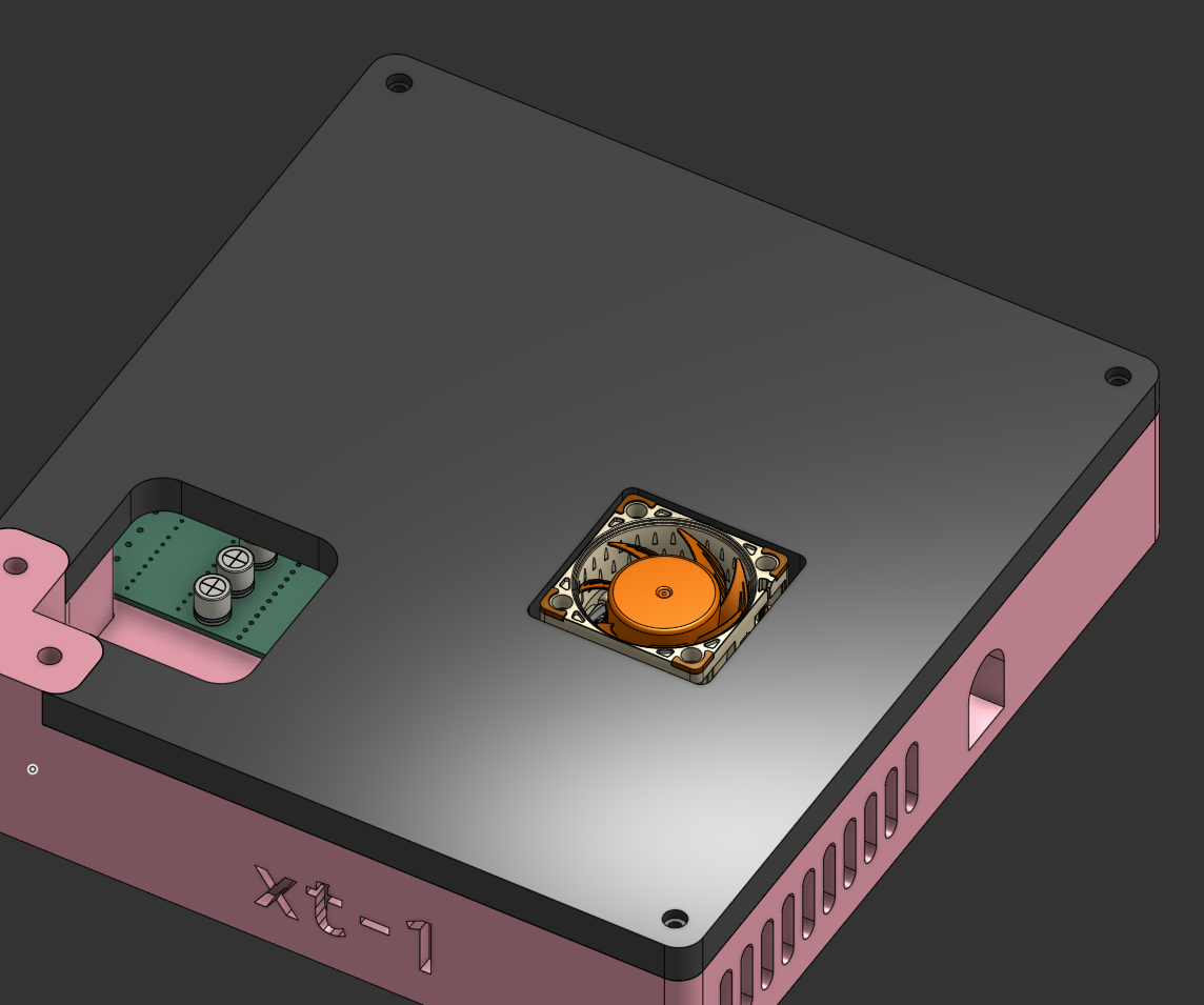
I've placed the fan mod described above down on the main board:
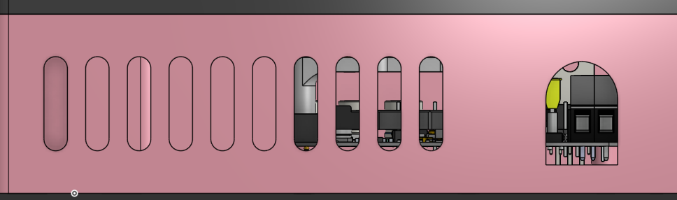
Additionally, I've added exhaust holes for the hot air to escape:
Minor Fixes
These aren't on screenshots in the journal, but here are some minor fixes I implemented for consistency:
- Mounting screw shafts for objects on top of the gantry extrusions have been reduced to 10mm, allowing for M5x15 screws to be used throughout the gantry. This has also happened on the toolhead, but just to make the screw size a bit more understandable (not at exactly 10mm though).
- Gantry object screw shafts have been inspected and fixed (I had found holes in some areas of pulley holders)
A lot of the time from this journal section was devoted to working on the BOM. I should be done with it tomorrow.
2025-07-28/29 - Journaling
Estimated time: 11 hours
I've worked on the BOM for the two days this entry is allocated too. I also fixed a few things, which I'll list now: - I've made some screws more universal throughout the build (you'll see holes and raised bits on some of the stepper/gantry mounts to save screw usage) - I've fixed some mounting issues with the bed in CAD (wasn't being displayed right)