
Total Hours: 61
Day 1 - Intial Planning (Jun 11)
This day is more of an summary of my previous thoughts and plans for this printer. I have been somewhat planning this printer rebuild since I bought it a few months ago, so I have some components for it already, but haven't started a full CAD model yet.
The primary goal for this printer is fast PLA and ABS printing, and a platform I can expirement with true non-planar printing.
Gantry
Although I initially wanted to just use a Voron Trident gantry, I found the Monolith gantry. Its much more rigid and has a shorter effective belt length for better input shaper graphs. However, I don't have the capability of printing high temp enginnering materials, so I can't just use printed motor mounts without them melting over time. So, I am planning on redesigning it for CNCing some parts. I plan on using my school's CNC to do this, so it doesn't count towards the project budget.
Parts I have - Rails - Belts - Some Motors
Parts I need - Bearings - Pulleys
Z Axis
I want to do a triple Z that can tilt to bed for future non planar printing. The example I found that looks rigid and precise is the Annex engineering K3's Z axis. But its a belt driven Z, so its somewhat expensive. I already have leadscrews from the stock printer, so I decided on adapting K3 Z for leadscrews.
Parts I have - Rails - Leadscrews - Motors
Parts I need - Bearings (For Maxwell coupling) - Rods
Toolhead
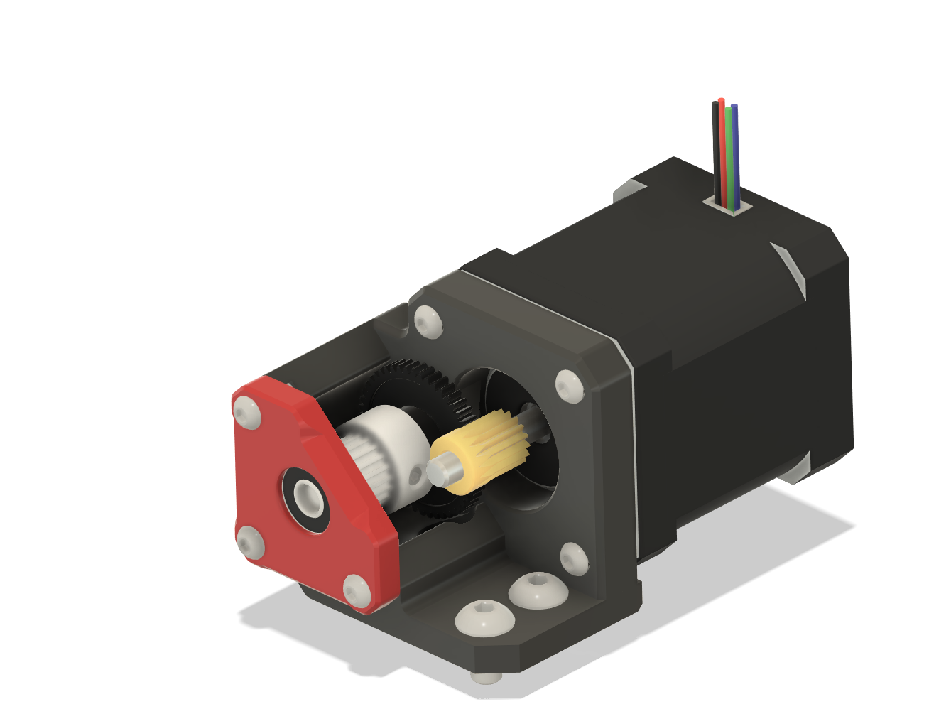
Currently I have a Peopoly Lancer Long hotend and the parts for a bmg extruder, but no good part cooling solution. On my ender 3 I am using the same parts with 2x 5015 fans for my cooling, but its too little cooling for fast print speeds. So I want to use higher cfm cooling, either 3628 axial fans or an external 7075 CPAP Fan. Using a CPAP will be an intresting design challenge because I will have to optimize my ducts a lot more that I would for 5015s or 3628s.
Recently I found the Monolith Gantry's creator tested a fully slm toolhead. It gave very good input shaper results since it was almost entirely one piece and supported the hotend near the bottom. If I can somewhat replicate that design, and manage to keep it low cost, it would give very good performance (> 50k accel without any artefacts).
Parts I have - Hotend - Extruder
Parts I need - Part cooling fans
Other
I have my frame mostly planned out, using a lot of the original ender 5 frame, but extending it in the x-axis for more travel and adding a top hat. For the electronics, I managed to get a cheap Fystec Spider and already have a raspberry PI, but I need to design the full electronics enclosure.
Parts I have - Frame - Mainboard - Rasberry PI - PSU
Parts I need - Wiring - Panels - Probably a lot of stuff I forgot
Hours Spent: 3
Day 2 - CAD started (Jun 18)
Created a new frame using some of the extrusions from the base Ender 5. Primary goals of this frame is to maximize travel from using 400mm rails and still have space for large toolheads. I then added the 9mm 2wd configuration of the Monolith gantry as a placeholder. Soon I'm going to modify it to add a strucural front brace and make it attach to the extra 2020 extrusions on the side and back rather than only the gantry extrusions.
I started planning the Z axis by placing the bed for keeping the most usable bed space. I only have some extra extrusion left over, so I'm figuring out the extrusions for the bed framing.
Hours Spent: 3 Total: 6
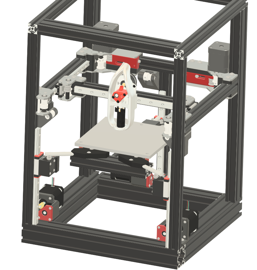
Day 3 & 4 Starting From Scratch (Jul 26)
I decided to restart this printer design to be a 160 mm3 printer. The 3 main reasons why I decided on this change was the cost, weight, and usability. With the Ender 5 frame, the panels were 555x700mm and would have cost $30 each and were taking up a lot of the budget. And this massive frame and large panels would have made it weigh too much to carry myself. This new printer has a footprint of 330x330mm and will weigh significantly less. Also I knew that 95% of parts fit withing a 160mm3 build volume.
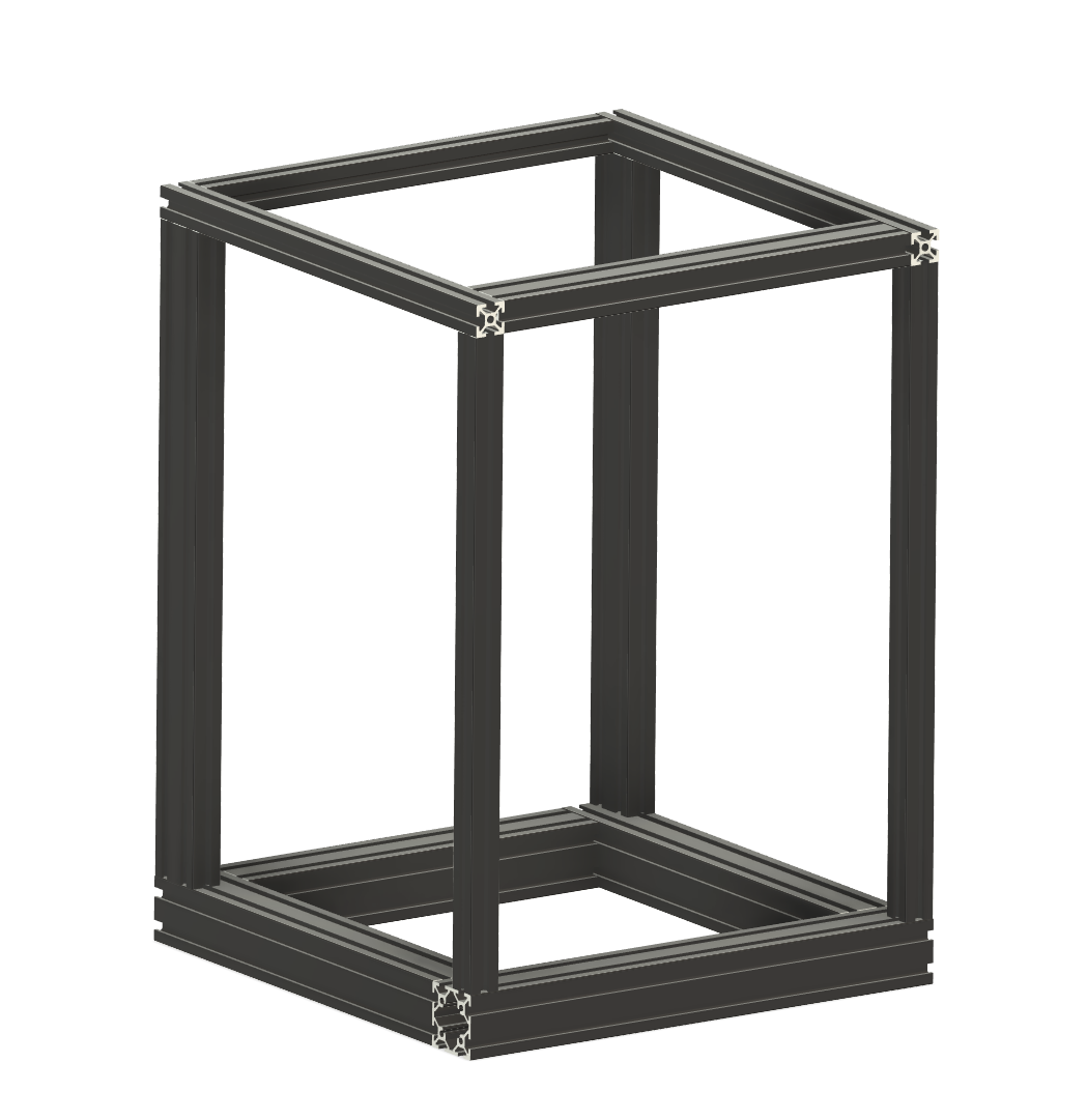
Frame
The Frame was designed to use a majority of parts from an ender 3 pro, some extrusions from the ender 5 and some extras I had on hand. The main difficulty and what I spent the most time on today was making the gantry large enough for the whole 160mm travel for the bed and have some overtravel for docking and undocking probes. Another constraint for the frame design was the panels. For cheap panels I needed to keep them all the same dimensions.
After playing with frame sizes for a while I landed on this design, which gave me 170mm X travel and 163mm Y travel, with 330x460mm Panels.
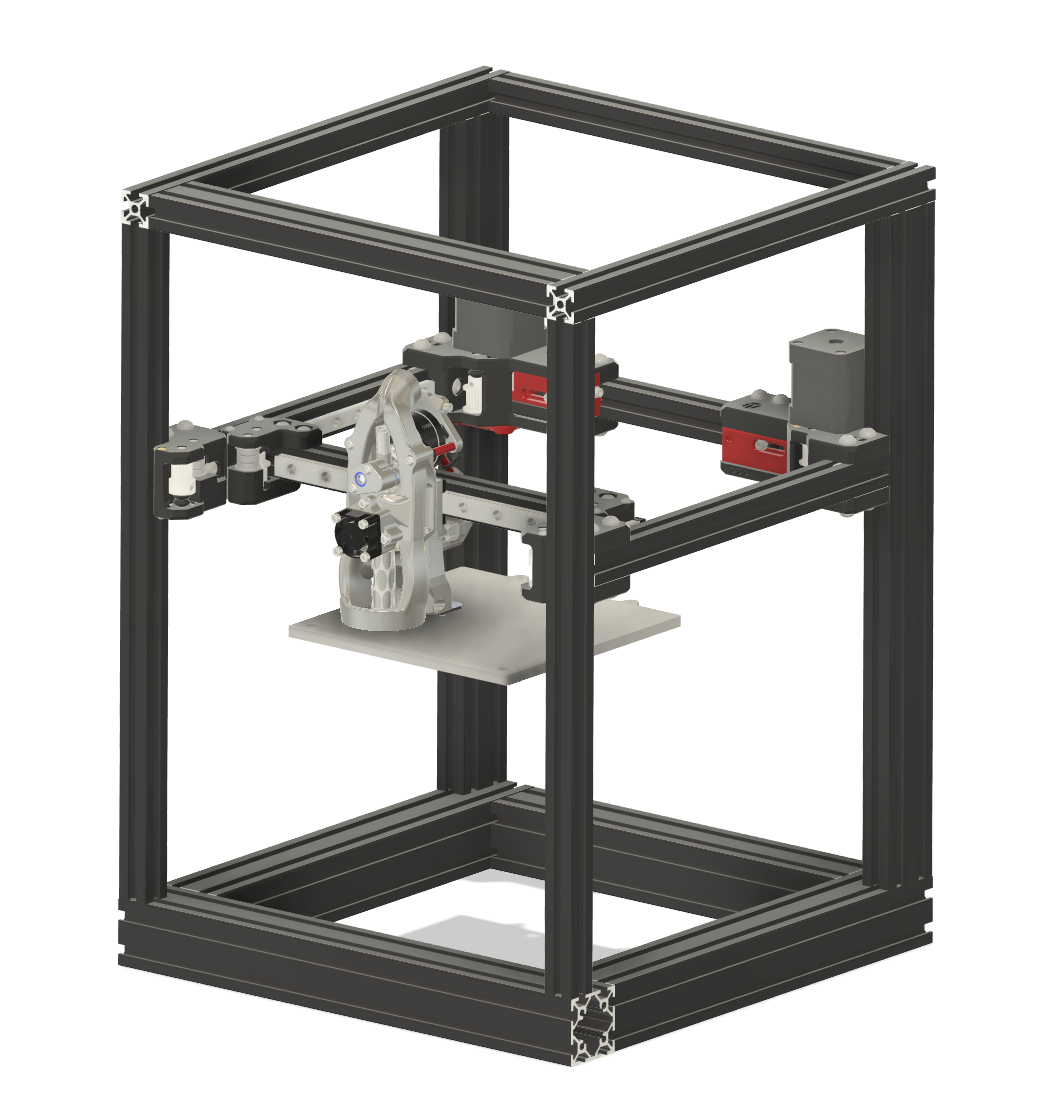
Gantry
I decided to stick with a monolith gantry-based design, to be able the get high preformance. The belt lengths on this printer are 1080mm compared to the 2.4m belts on the E5.
So I get to resuse my motors, belts and some hardware, but I will need to redesign the motor mounts to use lasercut aluminum.
All of the parts will be modified, but currently as a placeholder I put the stock monolith gantry, and UAPv6 Toolhead.
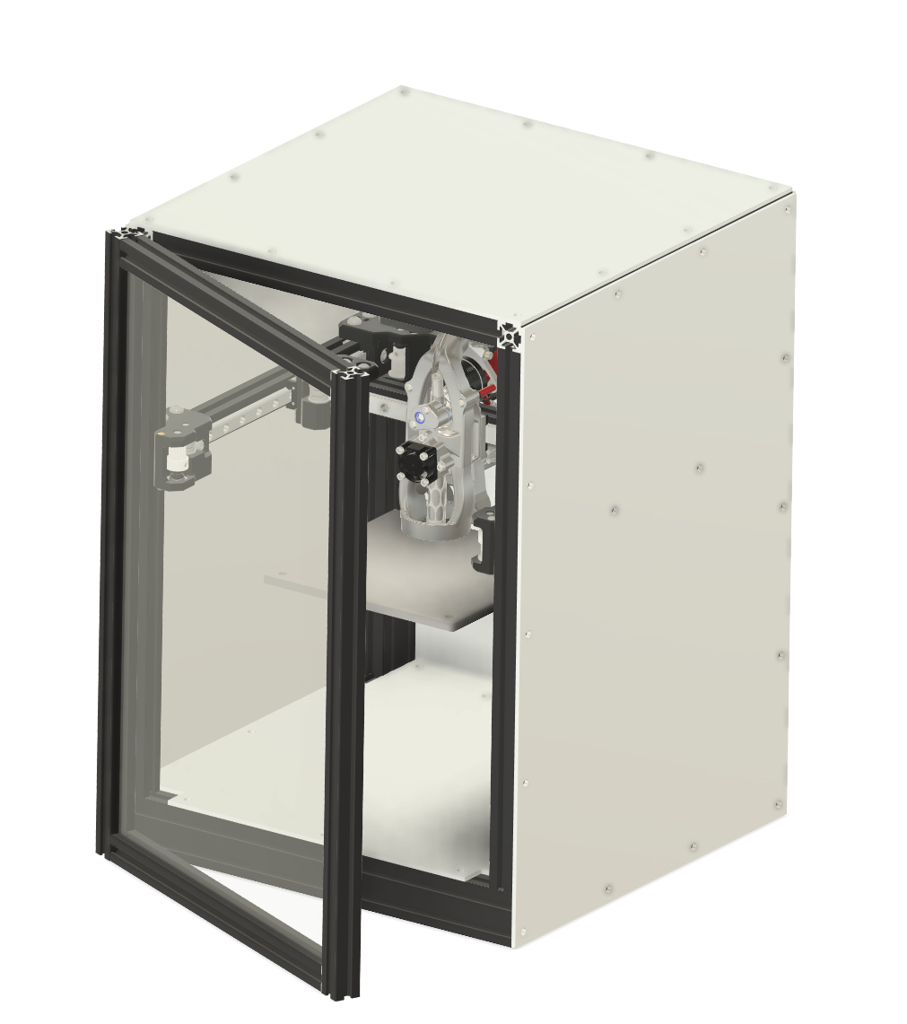
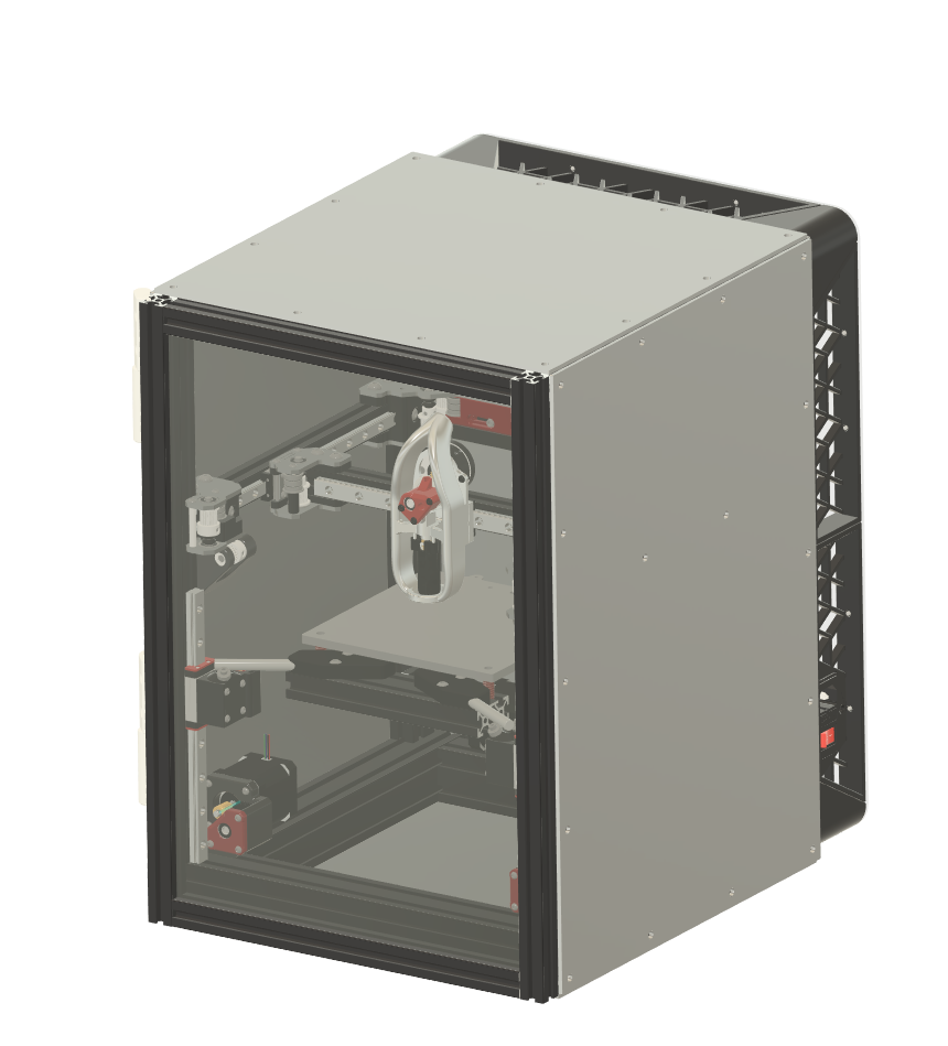
Panels & Door
Part of designing the frame was ensuring I had enough extrusion left over for a door, so I can get better chamber temps(I'm hoping for 70C).
I will have to drill and cut panels my self after ordering the 330x460mm panels from misumi, because its the cheapest way to get structural panels.
Parts Sourcing
I made a spreadsheet to keep track of all of the part costs. I started by making it for the Ender 5, but saw that the total parts cost would excede $350 because the panels would cost $150. So when designing and planning the 160mm printer, I made sure to reduce costs wherever possible. The main cost saving I manage was: Panels - Using Meviy and discounts; 5 panels at $15 per panel Part Cooling - Found much cheaper alternatives at $40 for fan and $5 for ducting compared to the $90 previously Linear rails - Most linear rails cost around $20-25 per rail even with short 200mm rails that I needed. But I found BST motion that gave me the price of $63 for all 6 rails
https://docs.google.com/spreadsheets/d/190TWAfKuzCkUHcKWP5val5u4-TL7WqxvR4hfKsAo7_s/edit?usp=sharing
Hours Spent: 15 Total: 21
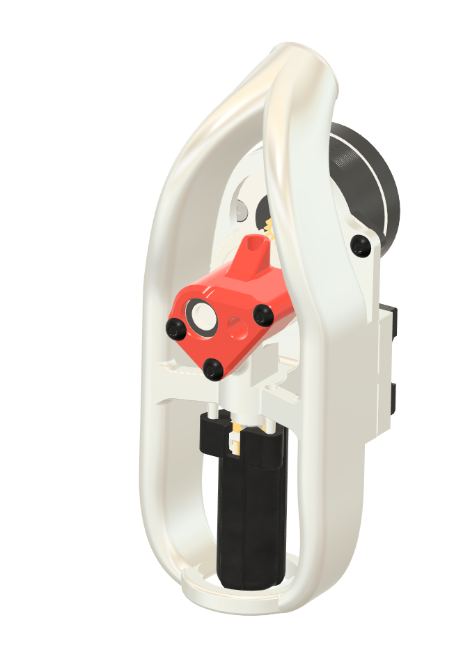
Day 5&6 - Toolhead & More parts sourcing (Jul 27)
I decided to go with an SLM toolhead for the best rigidity possible, and to have good clamping force on the belts. I designed a 3 part toolhead with the Monolith Belt Clamp and the larger body toolhead that has ducts and extruder combined, with an abs-cf extruder housing.
I found an alternative supplier for the panels to reduce cost even further, since I forgot to acount for shipping and taxes previously. I also updated all of the parts to include shipping and taxes to find a more accurate total cost, since I was close to $350. Currently the total cost is $357, so I might have to swap to an primarly fdm toolhead instead of slm.
Hours Spent: 12 Total: 33
Day 7 - Z Axis (Jul 28)
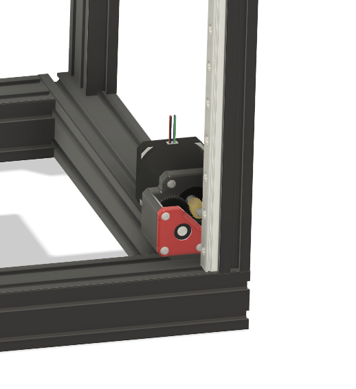
Because the bed is relatively light, I decided to use bmg gears for my reductions rather than a belt loop reduction to save space and cost. Because the bottom of my frame is made out of 4040 extrusions, I mounted my z motors onto of the bottom extrusions instead of under to get a good belt path.
Couple of other things I finished: - More cost reductions ~ -$15 - Created a cutlist for extrusions to verify that I have enough extrusion - Looked at existing wiring guides to start wiring diagram
Hours Spent: 6 Total: 39
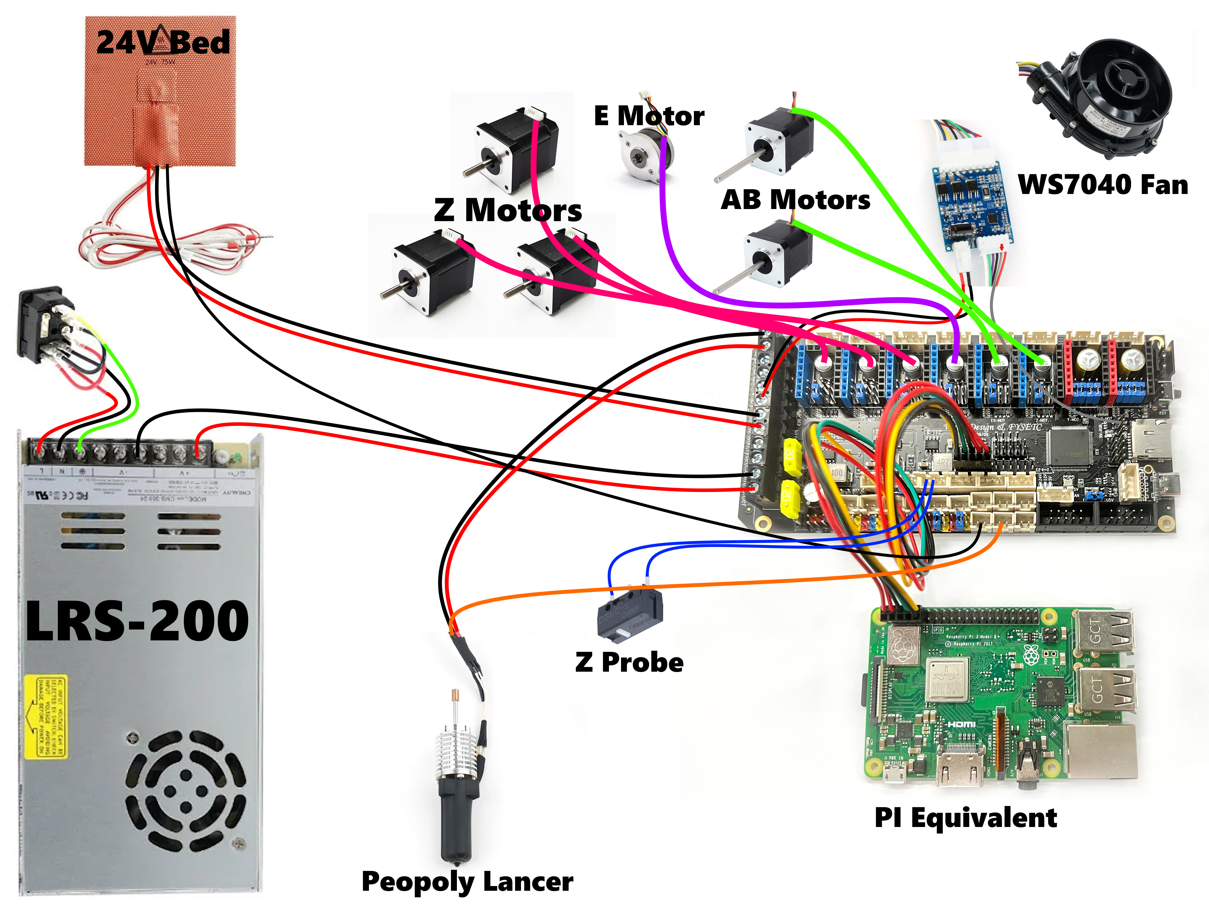
Day 8 - Electronics & more Z work (Jul 29)
Today, I made the wiring diagram for the printer and started electronics layout.
I also made the Z idlers, and worked on the bed side maxwell rod mounts.
Hours Spent: 4 Total: 43
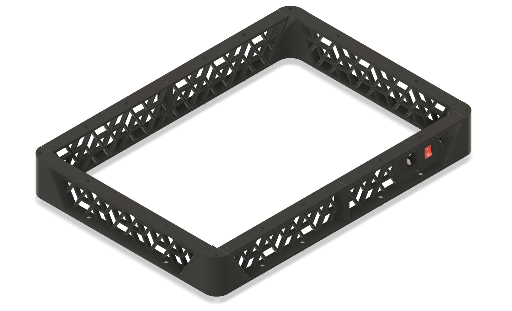
# Day 9 - Electronics Area (Jul 30) Today I designed the skirts for the electronics bay. A while ago I saw a video on 3d printed kumiko (japanese wood art) panels and thought it would look really good as skirts for a printer. I messed around with online kumiko generators to figure out what patters would look good as skirts, but I settled on a simple design which has a lot of open space for airflow.
Hours Spent: 6 Total: 49
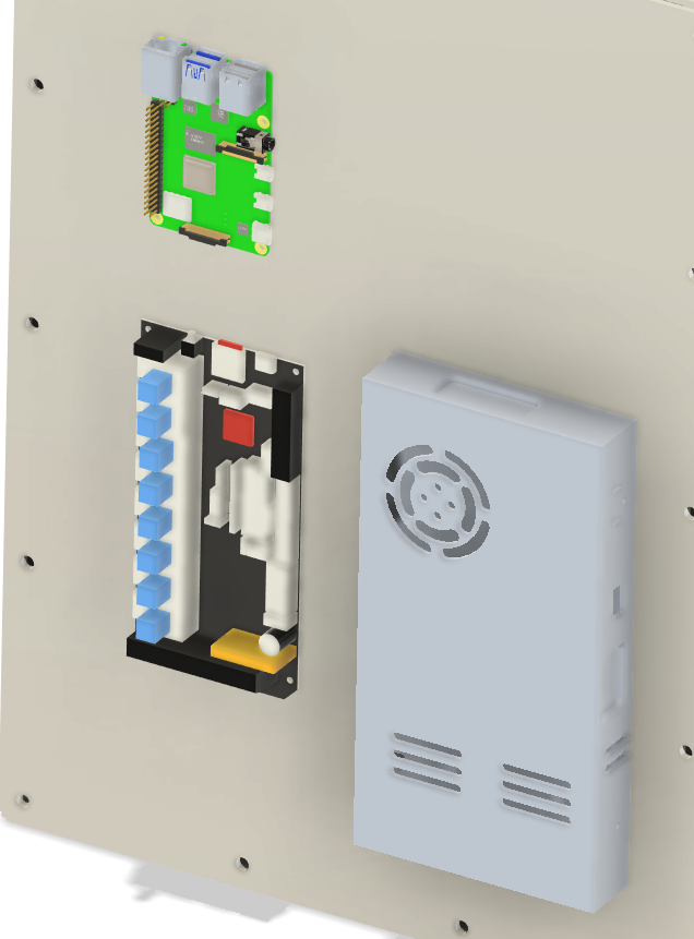
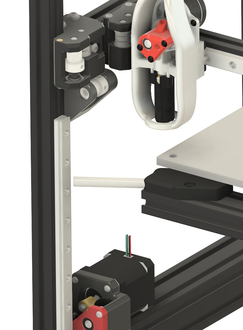
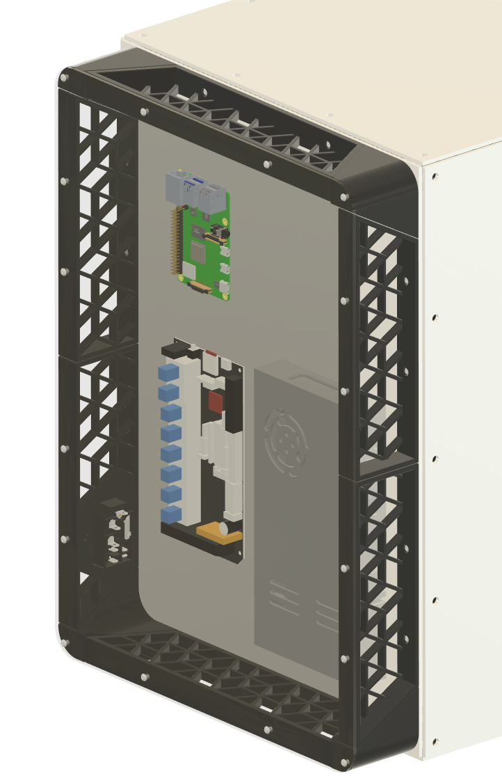
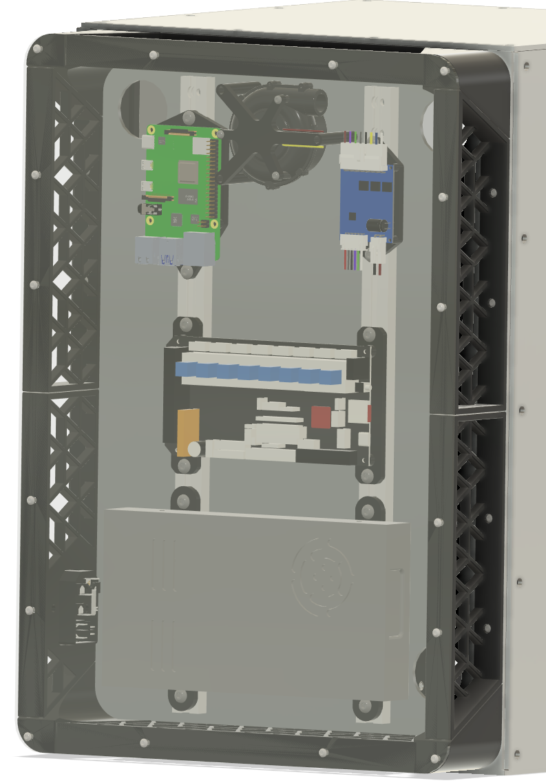
Day 10 - Electronics, Z, Gantry (Jul 31)
For the electronics I decided on using 2010 extrusion and designed the mounting brackets for all of the my electronics.
For the gantry I redesigned all of the gantry components to use a combination of fdm parts and 1/8" aluminum to use the extra from the panels. I also shifted the rear motor mounts 10mm backwards to allow for some overtravel in the Y axis.
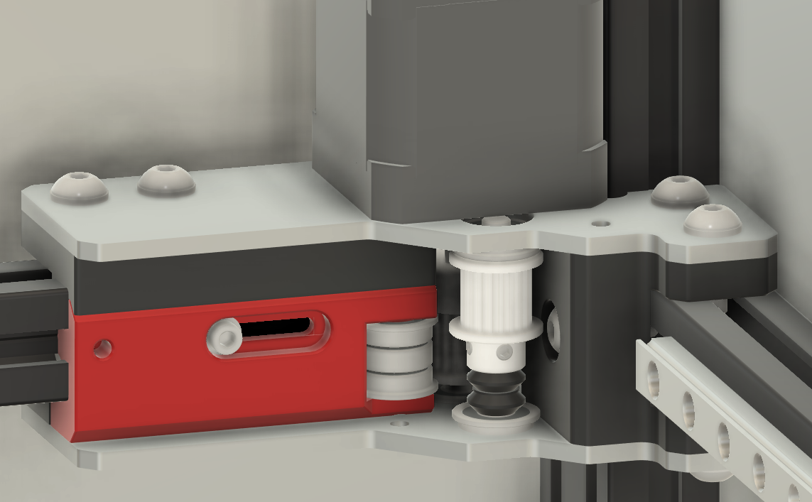
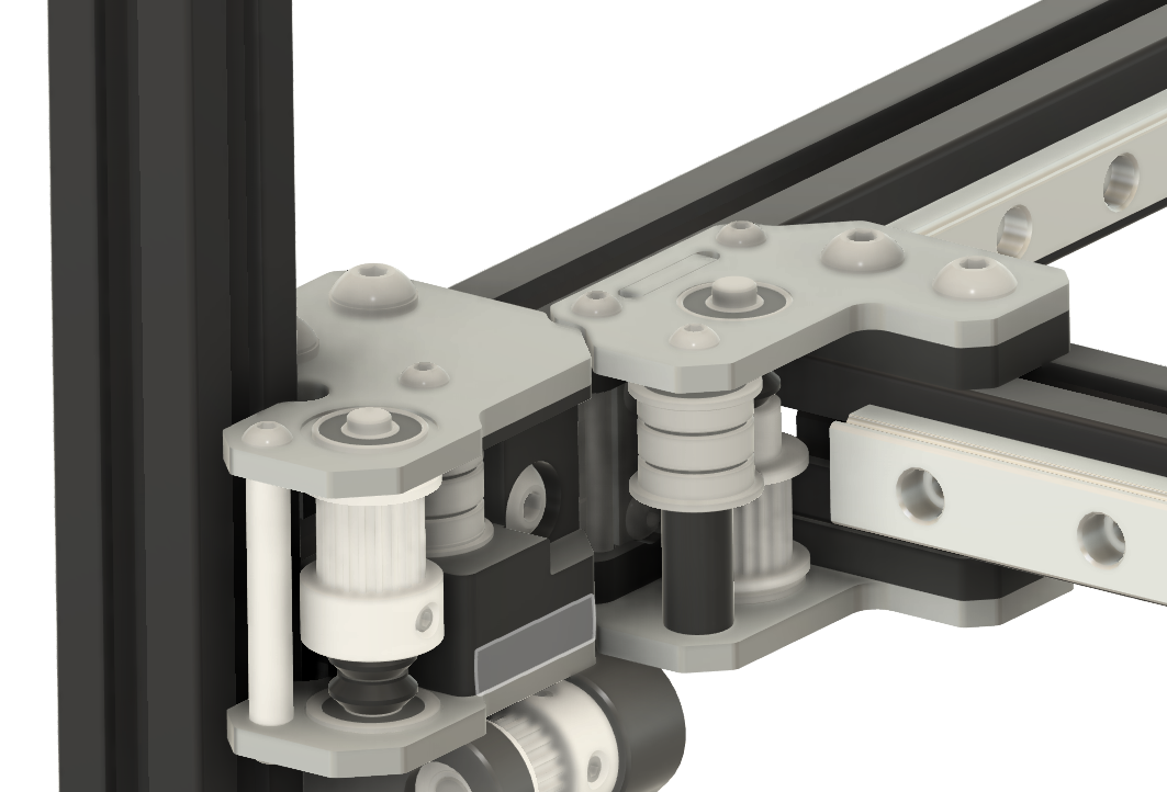
Finally I finished up the Z axis by creating the Z joints with the maxwell mounting.
And with a couple of other small parts that completes the printer.
Hours Spent: 12 Total: 61