
digital typewriter
A hybrid e-ink and OLED digital typewriter powered by ESP32
July 9th: Brainstorming and Components
Decided on project objectives and begun search to find components necessary to create the typewriter
Features - File storage system - Basic formatting (bold, italics, bullets, headers)
*more features could be added later, I would just like to get all the hardware figured out before i start getting overzealous with programming
- ESP-32 S3 becuase I just want to learn more about the platform and move over from arduino
- Decided on a hybrid e-ink and OLED display (similar to Ashtf's pocket mage PDA) to conserve battery life and have a smooth typing experience
- Using the same wide OLED from his new video!
- Found a cheap e-ink display commonly used for IOT labels
- Kailh low profile switches because a) they offer a good typing experience while still being small b) i have some
Total time spent: 2h
July 10th: More Componenets
More stuff? I dislike using modules, but I'll swallow my pride/succumb to laziness considering the budget and timeframe of this project (also modules mean I can do some prototyping on a breadboard)
- An SD card reader module
- With two SPI componenets, I will need to figure out a system to alternate between updating the screen and saving things into memory; luckily e-ink displays are bistable
- Battery management with a bq25185 module
- USB-C connectivity with power path management, suitable for a single 3.7V lipo
- I will need to step down the voltage with an LDO (XC6210B332MR?) for the ESP32
- 3.7V single cell lipo
- Current have a placeholder 1400mAh slim cell right for blocking
- Not entirely sure what I'm going to use yet, probably going for something slim that can fit within the side of the screen with as much capacity as possible
Currently I'm leaning towards buying and prototyping with these modules, then combining everything with a proper PCB.
Total time spent: 2.5h
July 15th: Ordering Parts and Designing the Keyboard
Ordered the e-ink display and sd card early for testing. The project is likely going to go over $150 anyways so making these purchases without the grant money should be fine.
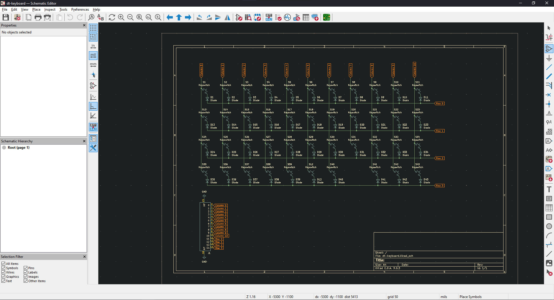
To keep the work going, I started work on the keyboard portion of the device. I decided to use mx spacing (19.05mm x 19.05mm) and created a keyboard layout similar to the JD40.
Heres the schematic I created in KiCad
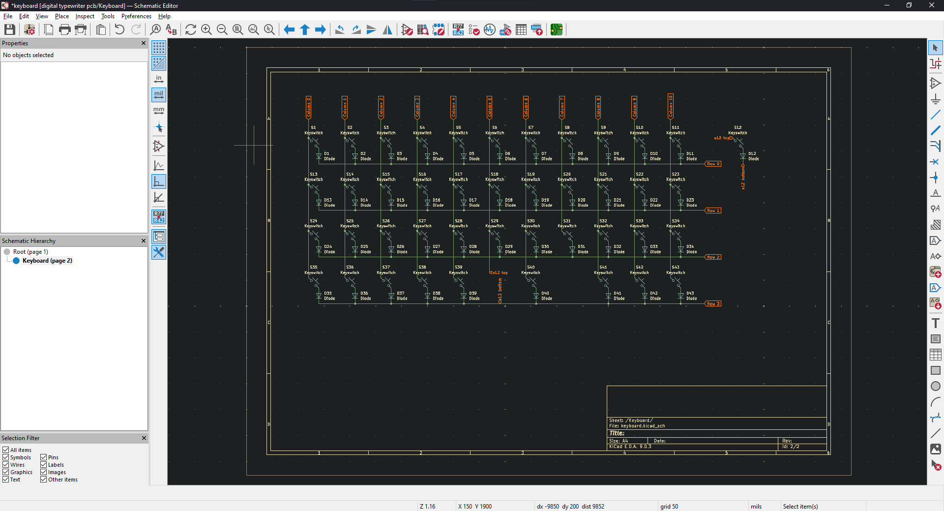
After doing some research, I belive that FFC cables will be the best to use in connecting the keyboard with the rest of the computer. As a design consideration, a slot will need to be cut into the mainboard to ensure that connections dont get reversed.
Total time spent: 4h
July 17th: FFC Connector and Laying Out the Keyboard
After sourcing a JST connector from JLC, I created and recreated the symbol and footprint of the FFC connector...
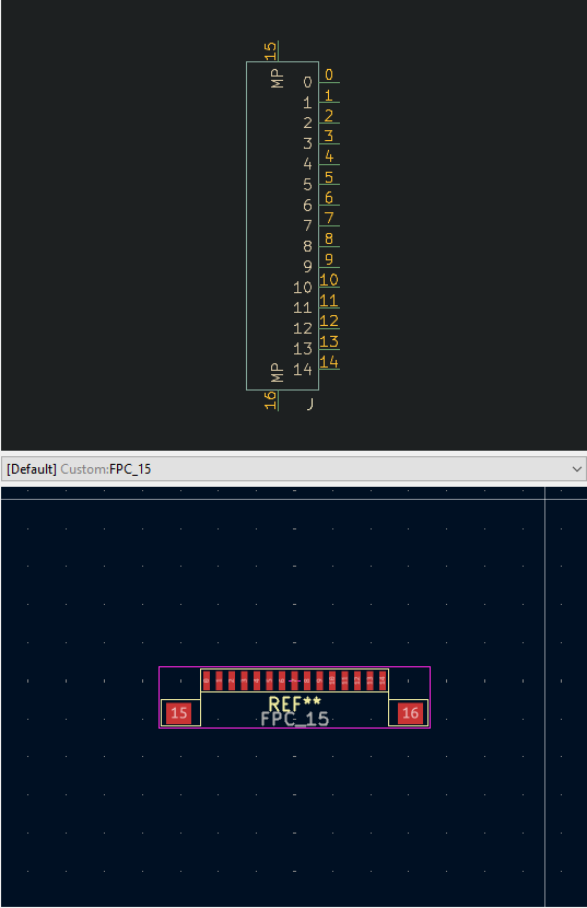
...then updated the schematic with the new connector.
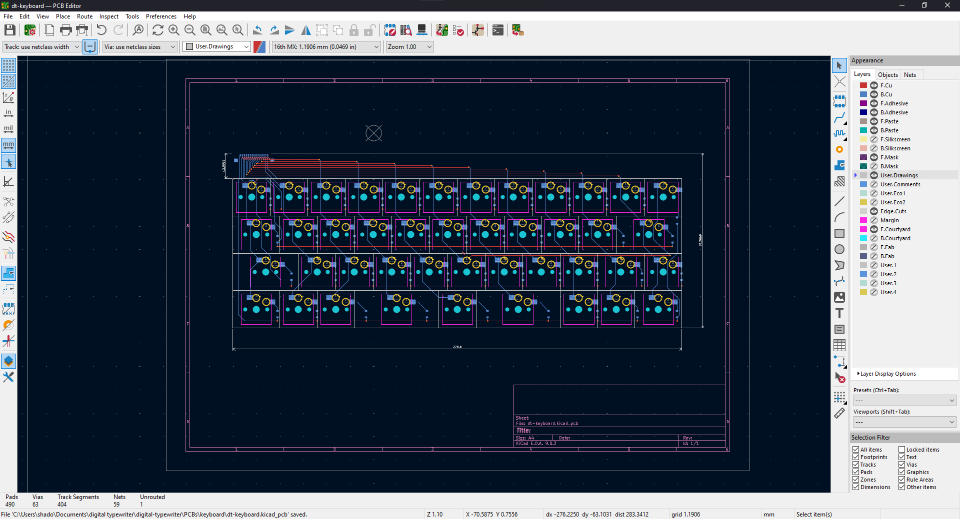
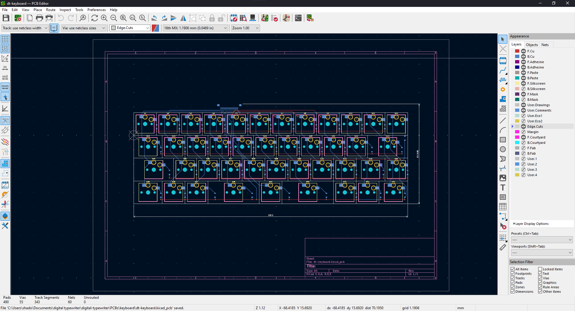
 Then I went through the tedious process of laying out componenets and routing traces. Because I'm using choc switches with MX spacing, I had to create new footprints based off of Scottokeeb's hotswap choc footprint.
I may try to make the keyboard even smaller by moving the FCC connector, but for now I am quite satisfied with my design.
Then I went through the tedious process of laying out componenets and routing traces. Because I'm using choc switches with MX spacing, I had to create new footprints based off of Scottokeeb's hotswap choc footprint.
I may try to make the keyboard even smaller by moving the FCC connector, but for now I am quite satisfied with my design.
Total time spent: 5h
July 18th: Fixes and OLED
I realized I actually misoriented the connector so I decided to just redo the entire system again, making everything more compact in the process.
Another conclusion that I came to is that the motherboard should be split into component modules—the lack of ability to prototype within this project and timeframe means that parts will definetly not work on the first try. By making parts swappable, I can mitigate the damage of each iteration.
I also decied to use a differnet OLED module that is now 64*256px. While that means I'll need another SPI peripheral instead of I2C, this module should be easier to implement and display more data.
Total time spent: 1h
July 19th: Power Management
I created the usb-c port program the ESP32-s3-wroom module with.
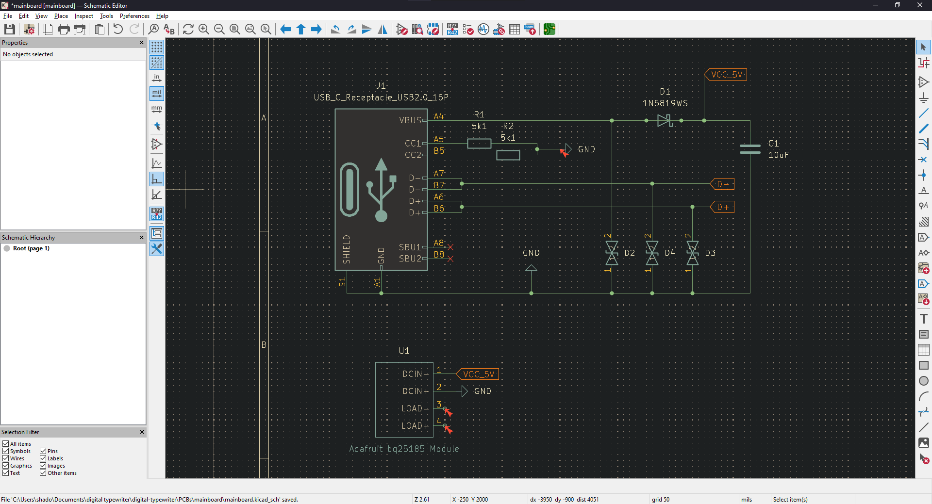 Because the battery module I plan to use outputs 4.5-3v, I settled on the TPS79533DCQR to regulate 3.3v to the ESP32-s3-wroom-u. It has a ~105mV dropout voltage and low noise—perfect for the ESP32.
Total time spent: 3h
July 20th: ESP32
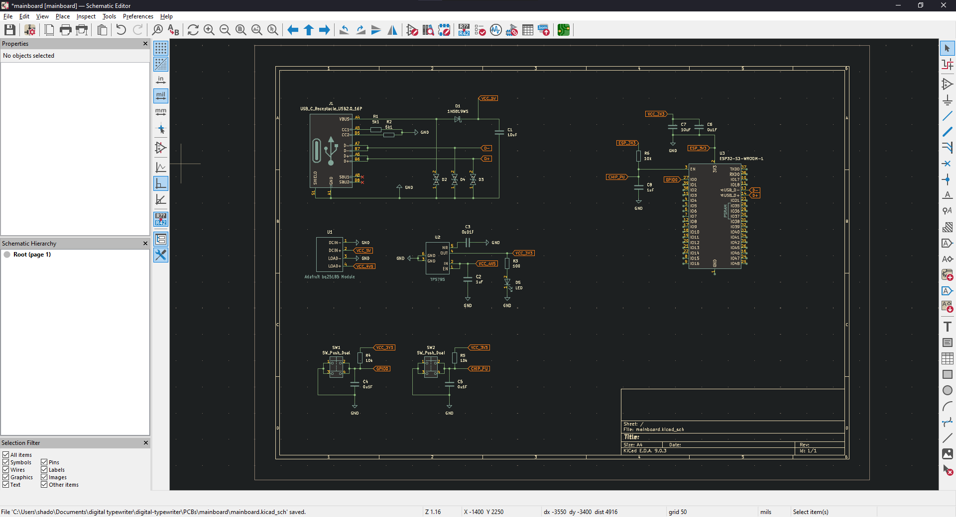
With the power situation figured out, I added in the esp32 and its basic peripherals to the schematic. I had some confusion about the power system and how everything was going to be grounded, but I believe that my schematic works properly now.
Total time spent: 3h
July 22nd: OLED Testing
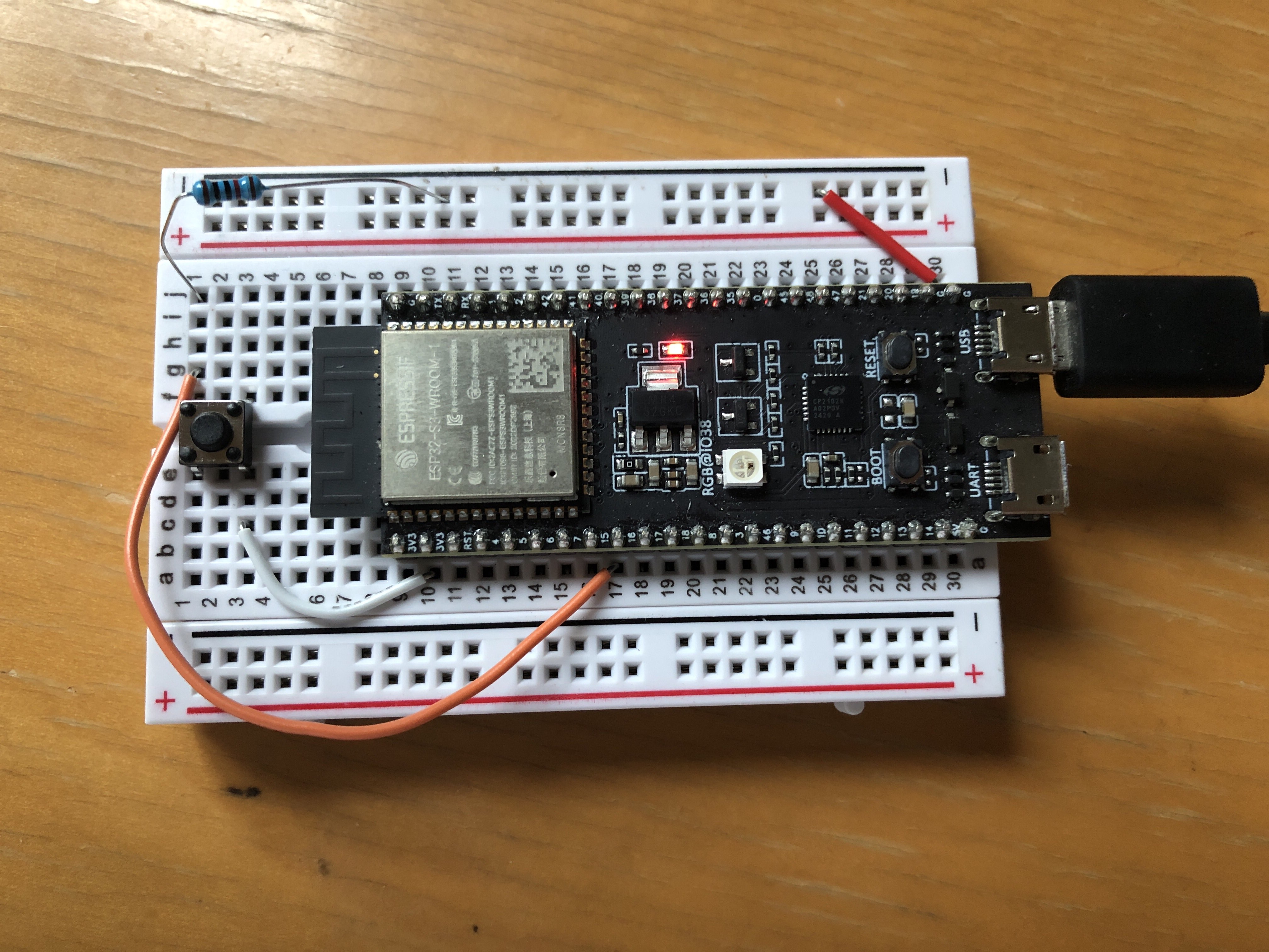
The OLED module arrived so I took the time to test it and gain some familiarity with using SPI on the ESP32. I (messily) created a small test circuit on a breadboard...
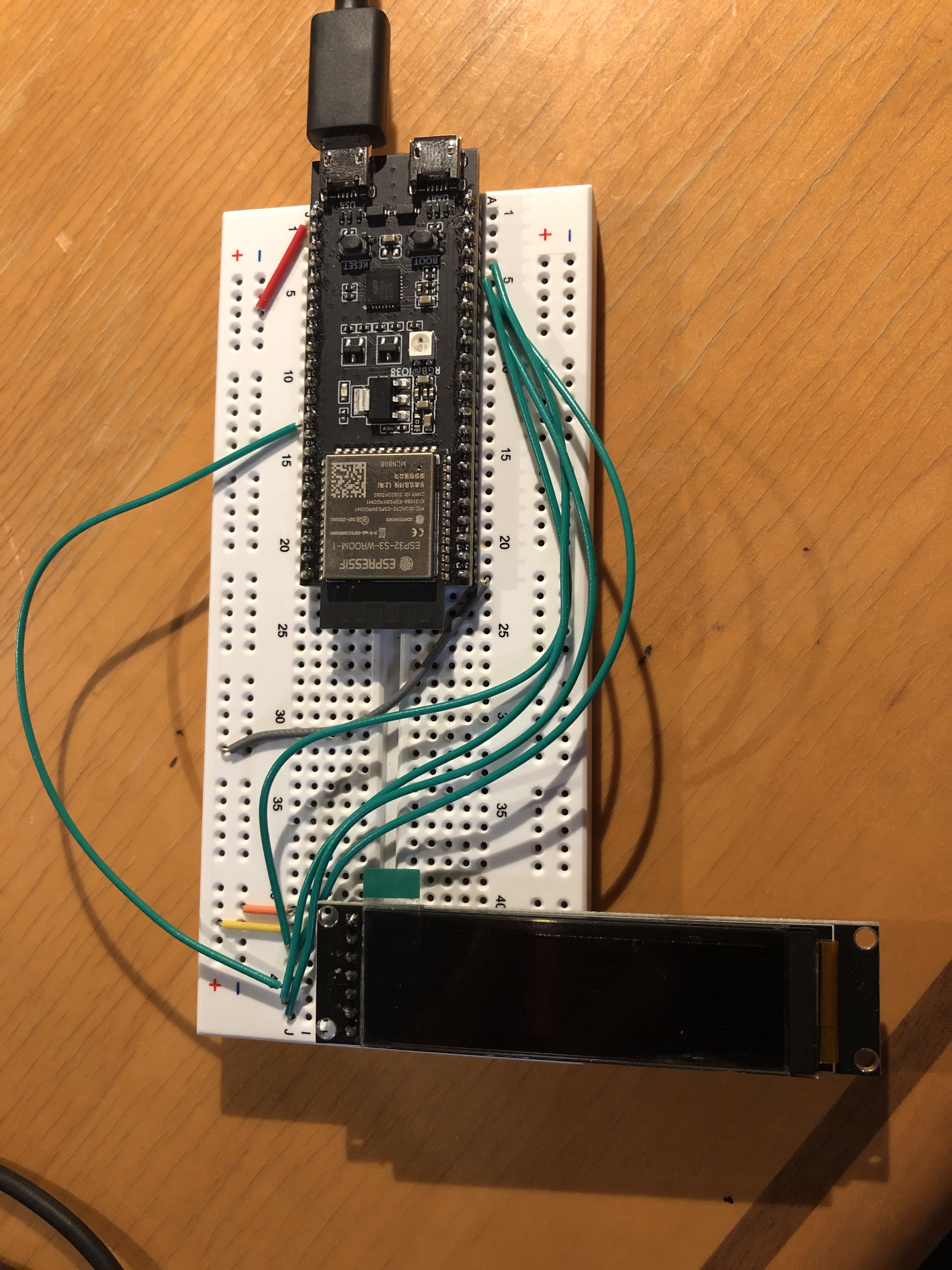
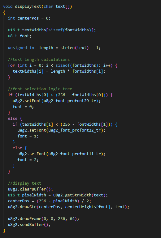
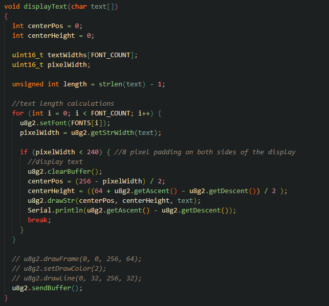
and wrote some basic code using U8g2lib. The idea is to have text be centered and have the font shrink when the text gets too big to fit on the OLED...
For a small test of the OLED module, I am quite satisfied wtith the result!
Total time spent: 4h
July 25th: VSPI and Optimizing OLED Testing
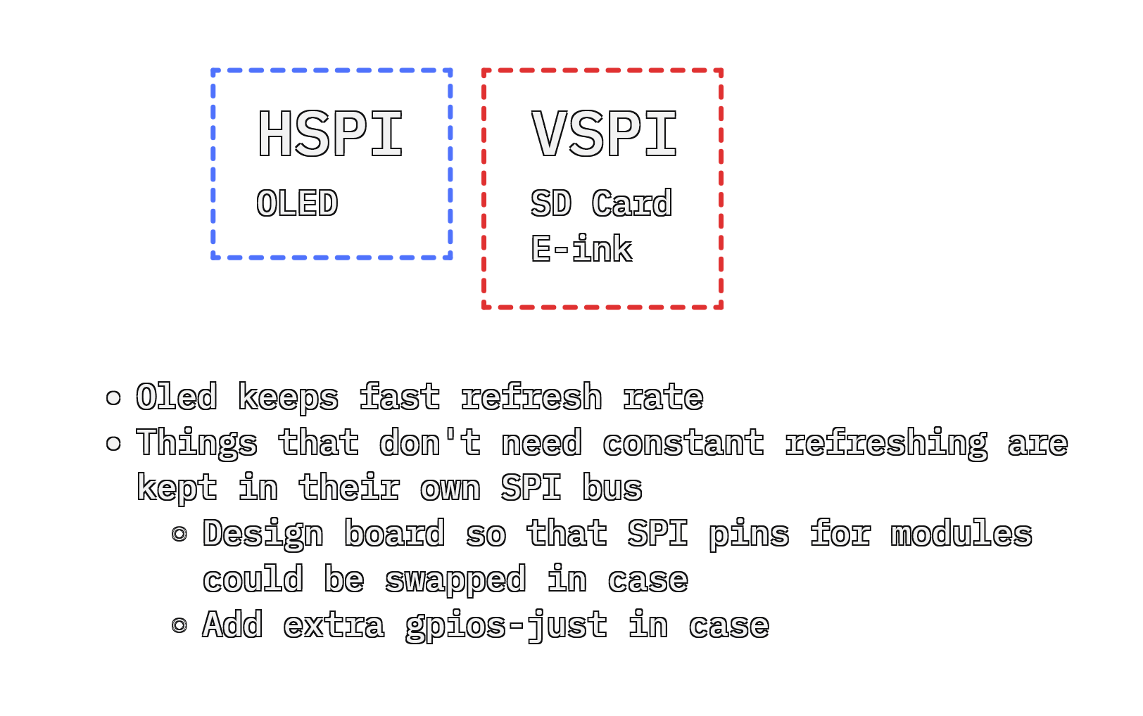
I took the time to optimize the OLED testing script (I'll be reusing this code for the final typewriter) to work with any U8g2 fonts and tested the VSPI bus.
With this knowledge, I decided on how I would distribute the SPI devices on the buses:
Total time spent: 2h
July 26th: Adding Peripherals to Schematic
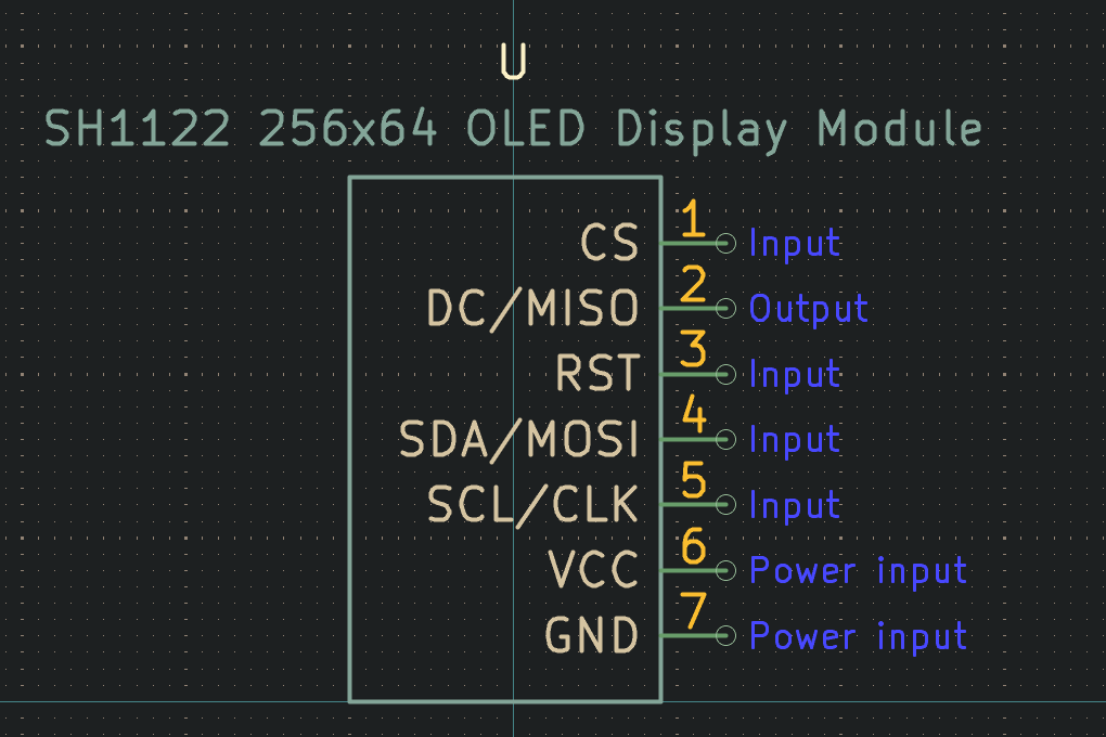
To finish up the schematic, I created the rest of the module symbols:
|
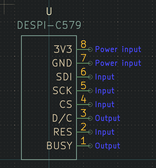
|
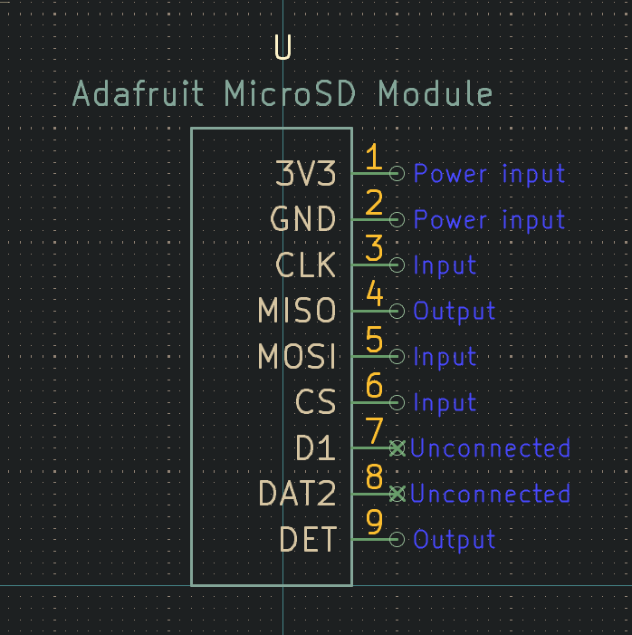
|
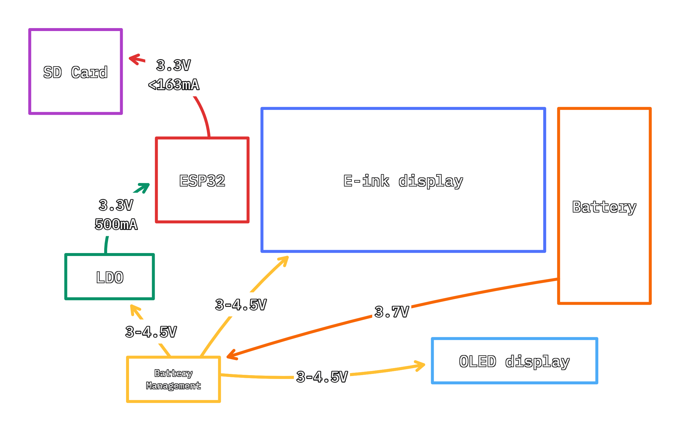
...and attached the power and GPIO pins for each module:
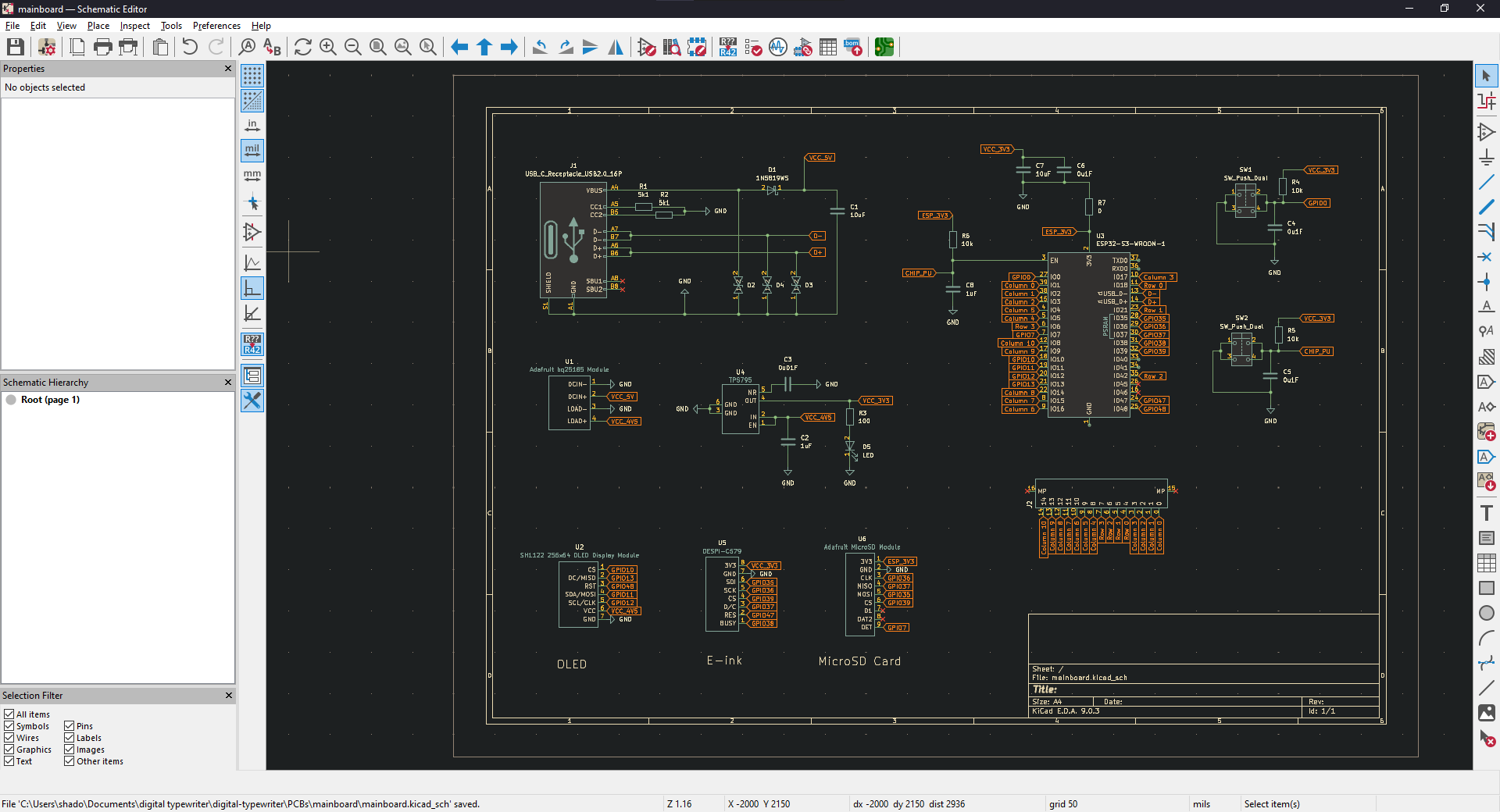
Pins will probably need to be moved around later to make routing easier, but thats a problem for another time.
Total time spent: 4h
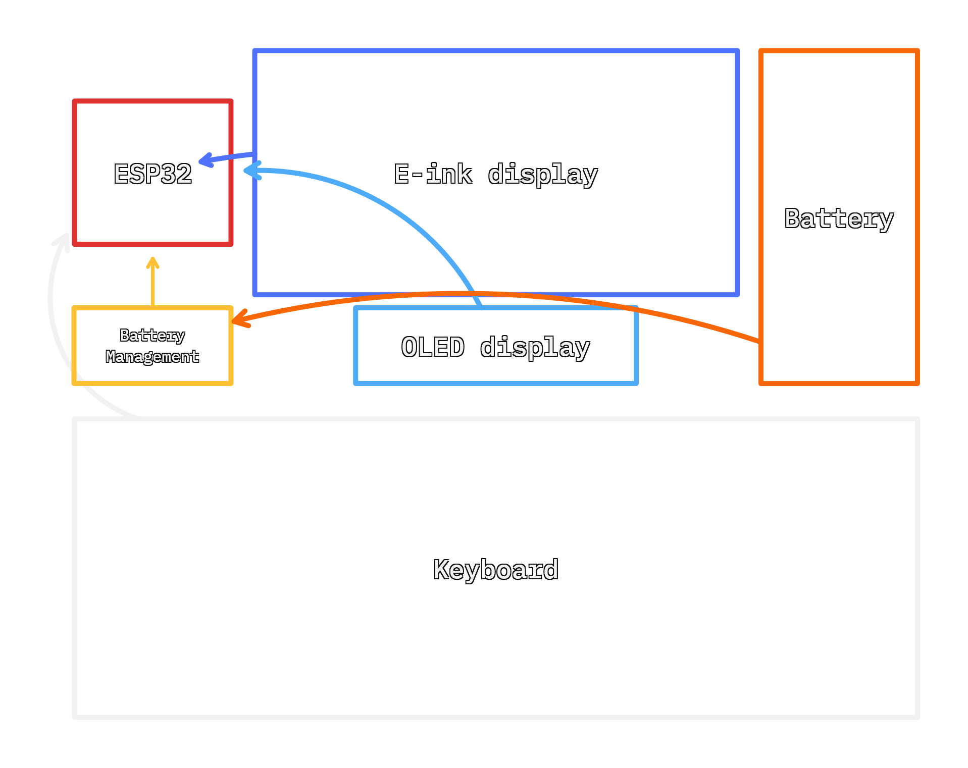
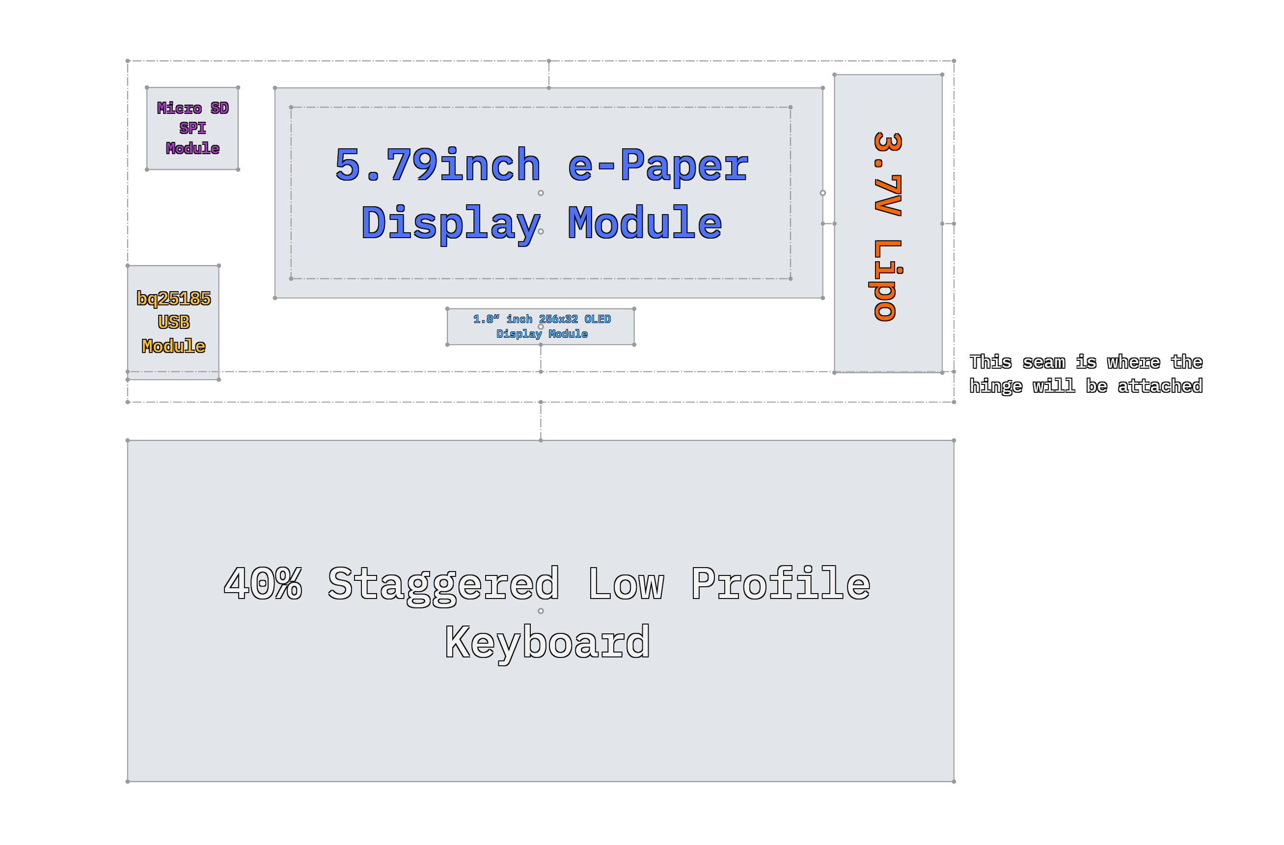
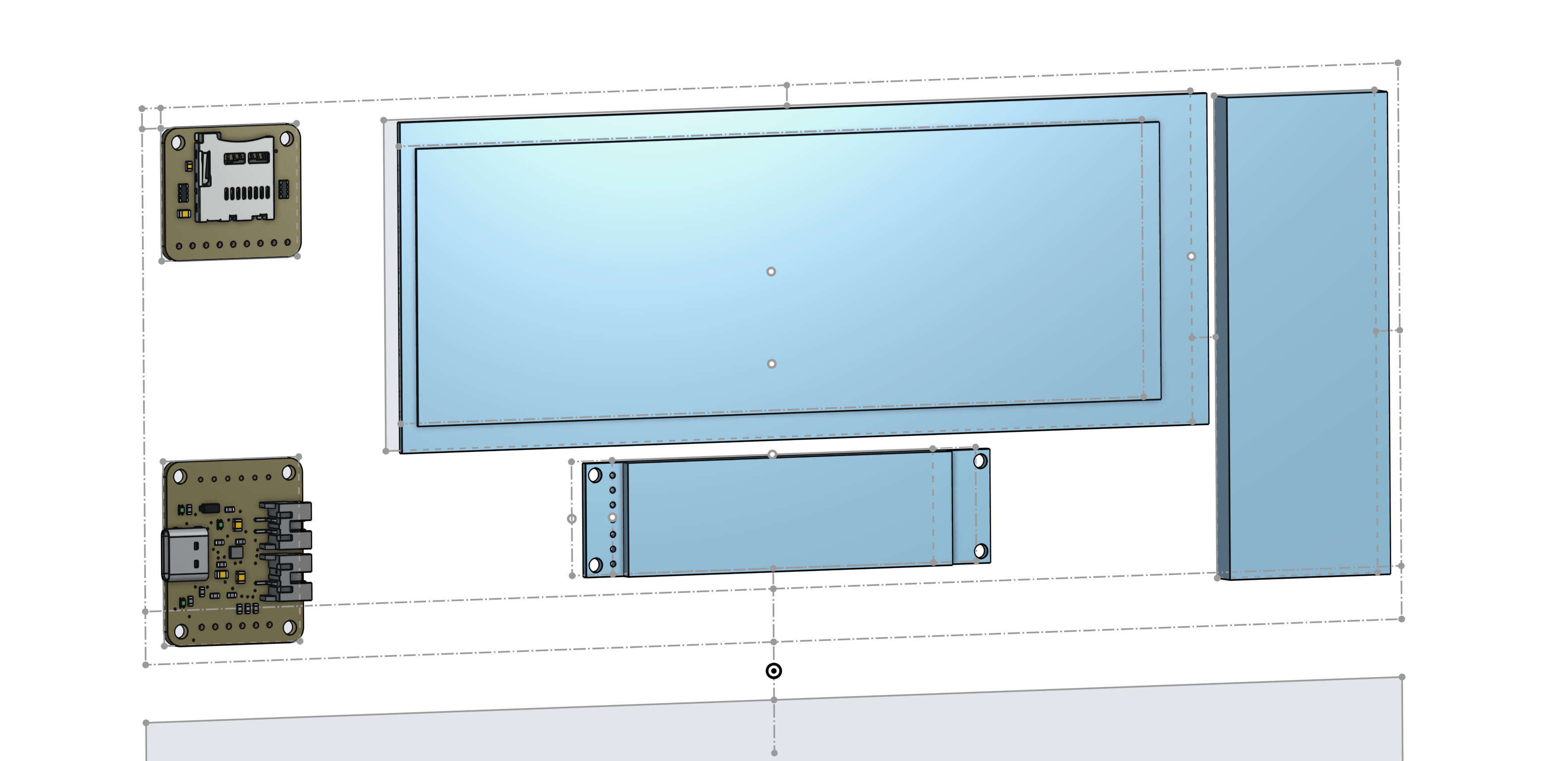
July 29th: CAD Mockup and Pre-layouting
Before I start the layouting of the mainboard, I wanted to get an idea of how everything would be wired with a quick cad model:
Then I started finding componenets on JLC for all the basic SMD components. Because the mainboard PCB will be 2 layer, I decided on 0805 size so that I could run traces underneath all the components if necessary.
I made a couple custom footprints (diodes, LDO, buttons) but the one that gave me the most headache was the USB-C connector. Not wanting to risk a faulty connection with the connector ordered from JLCPCB, I had to go into the datasheet and faithfully recreate the footprint and pin assignments:
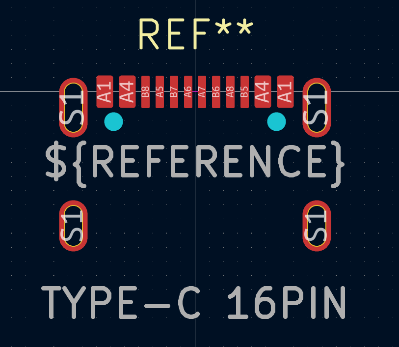
After that ordeal, I am much more grateful towards the uniformity of mechanical drawings and the standardization of USB connectors.
With this major headache out of the way, the only footprints left to design are the ones that will be wired to the peripherals—then I can start laying everything out.
Total time spent: 5.5h
July 30th: Deep Sleep Testing and Footprints
I took the time to test the ESP32's deep sleep and wakeup functions through the espressif example code. This was a rabbit hole. The serial monitor on Platformio suddently stopped working (probably because the ESP32 disconnected from the USB CDC when it went to sleep) and left me confused for awhile—I ended up switching to Arduino IDE and was able to get the ESP32=S3 to go into deep sleep and wake through ext0.
After that ordeal, I finished the footprints for the peripherals and organized everything in a diagram to check wiring (and redesigned the keyboard slighly to shift the ffc connector):
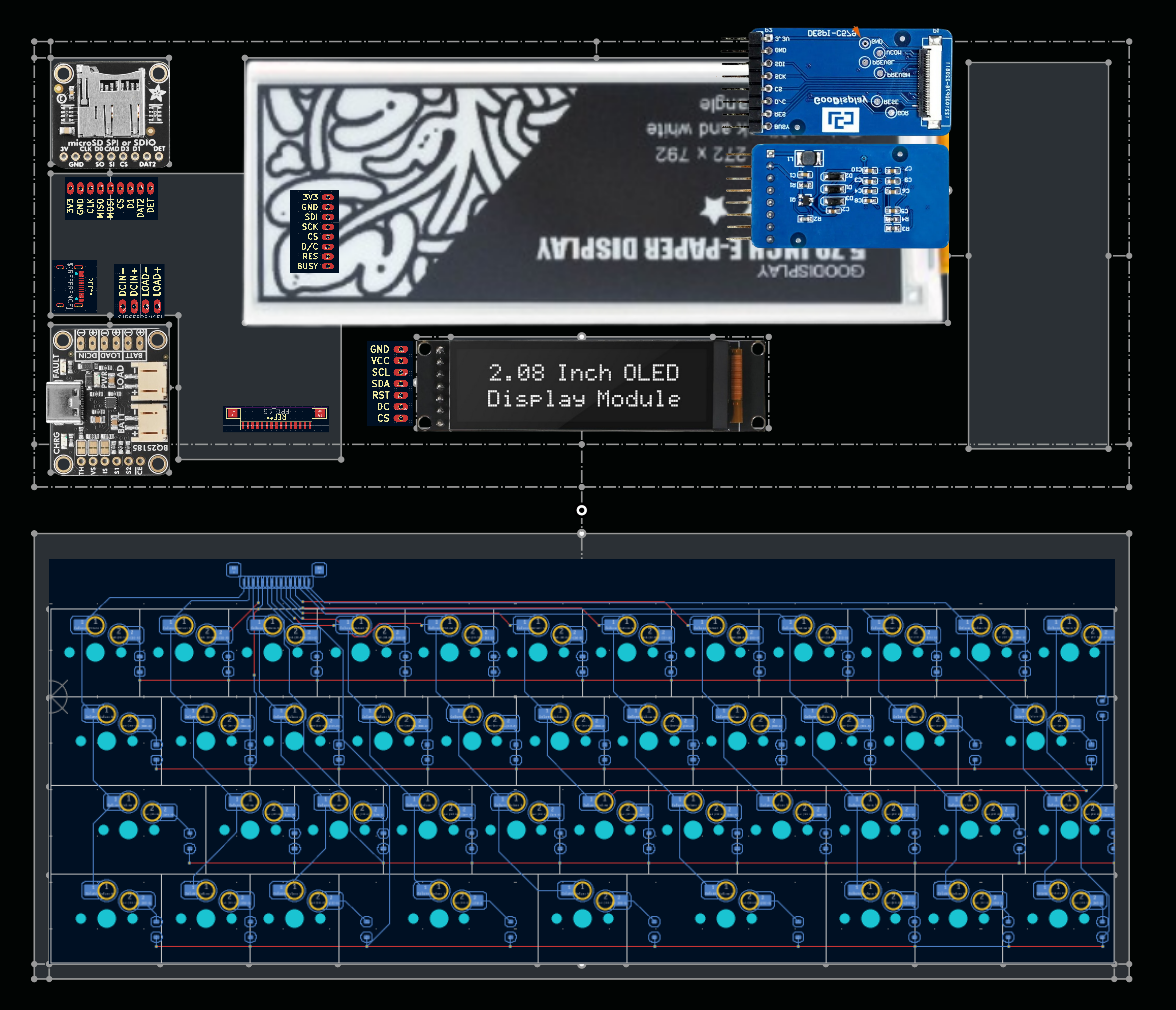
With a bit of finagling, I got all the componenets layouted and connected. I am folling this tutorial to make sure that my USB lines will function properly(I still need to add a ground plane and length match the traces).
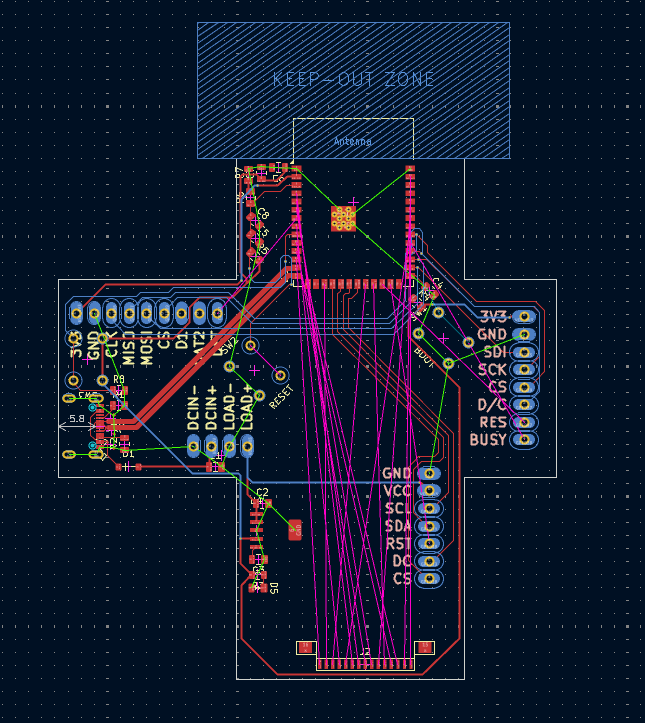
With this step done, I can add in the traces for the gpio pins and make space for some mounting holes
Total time spent: 6.5h
Month Day: Title
Total time spent: time