
Riptide
An Infinitely Expandable, Ocean Inspired Keyboard.
Total time Overall: 37h
June 1st: Started work on keyboard layout and matrix
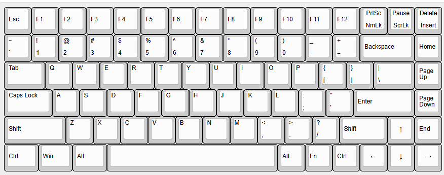
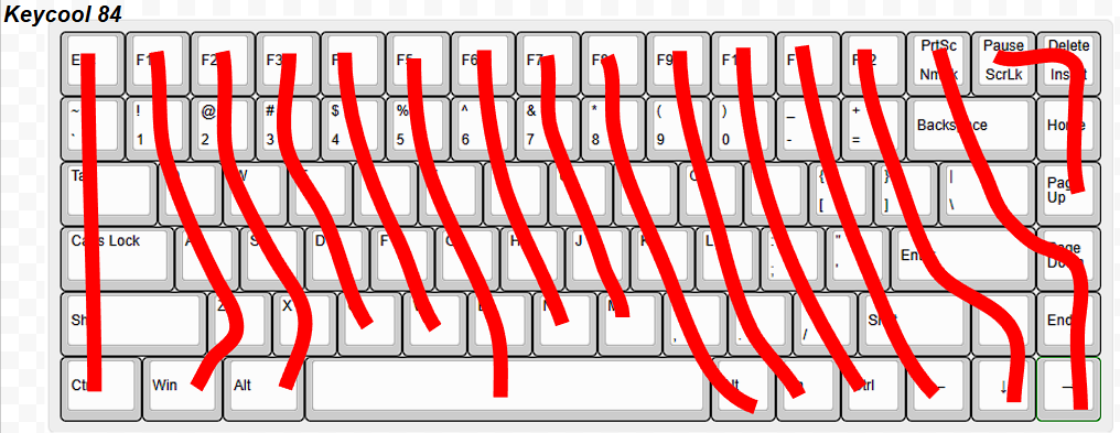
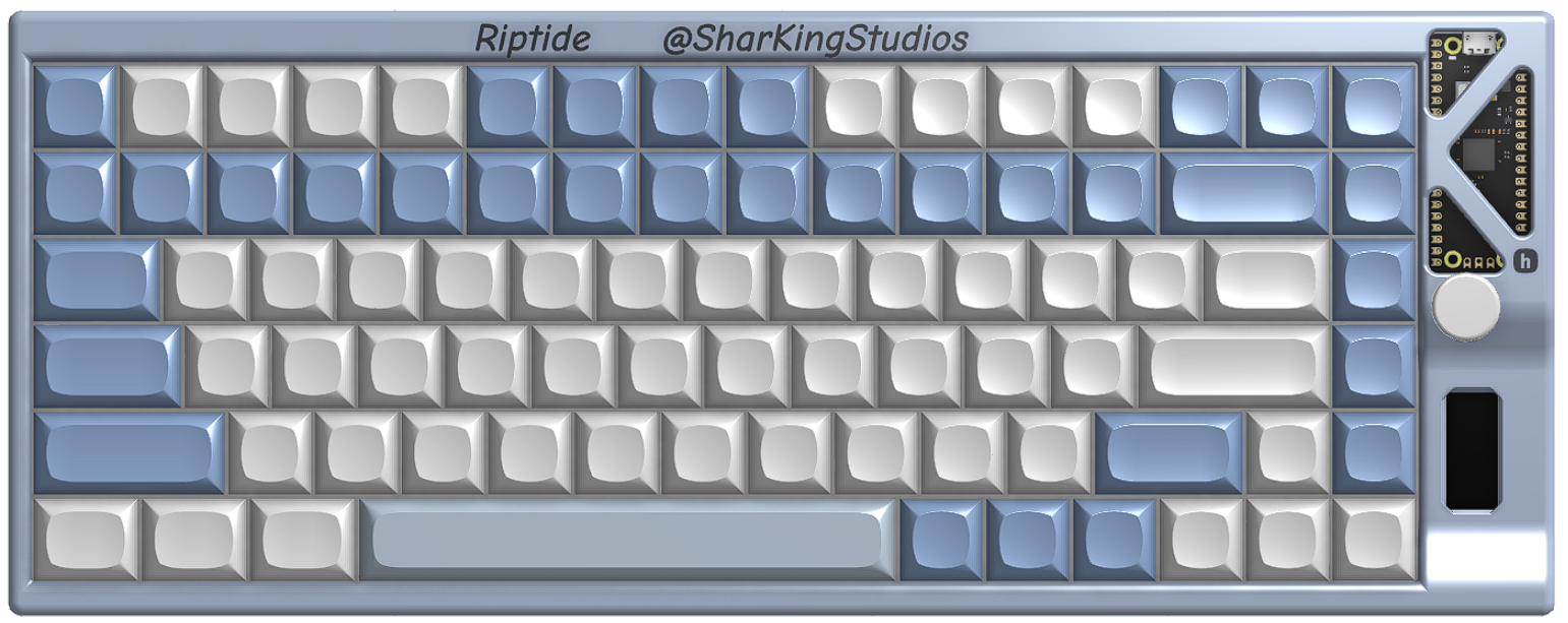
Today I just researched a bit into the different keyboard layout types. I wanted to keep the layout similar as my current (membrane) keyboard. I chose to use the Keycool84 layout as seen in the layout editor:
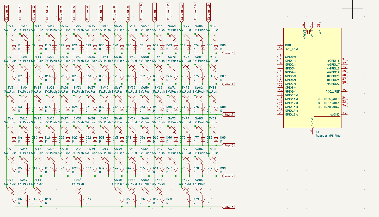
I also grabbed an old keyboard matrix I made when I was working on a keyboard prior to this. (This is about as far as I got lol)
Total time spent: 1h
June 2nd: Fixed the keyboard matrix
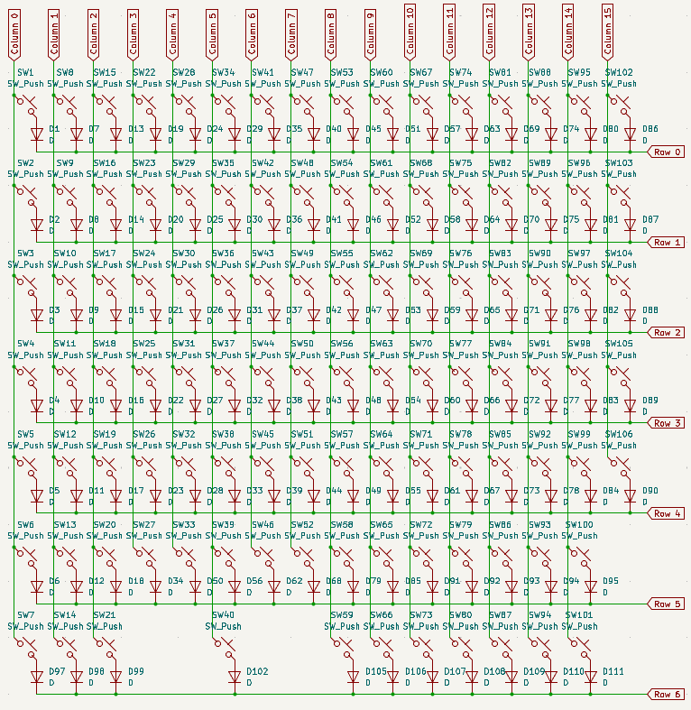
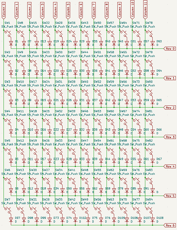
Today I fixed up the keyboard matrix to have it match my Keycool84 layout that I chose.
When I tried fixing
it for the first time I actually added even more keys lol:
At first I was trying to create the keyboard matrix based of of the physical location of the keys.
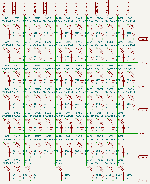
I then realized that since the keyboard layout editor would export the matrix data, I could make it much smaller.
Total time spent: 3h
June 3rd: LEDs and Infinite Expandability Support
Today I worked on putting together the LEDs in the schematic, wiring the pico to the keyboard matrix, as well as figuring out how I wanted to do the infinite expandability.
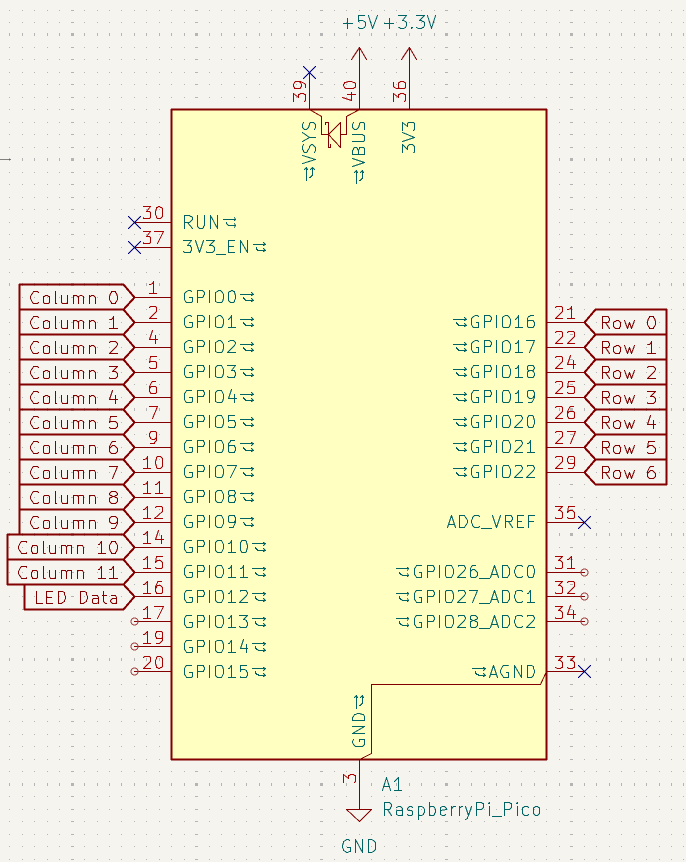
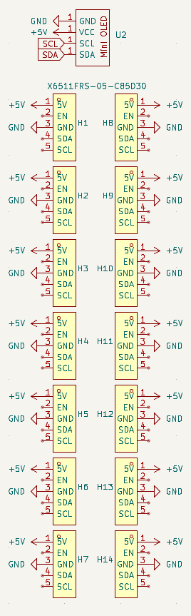
So I want to have 5 pins for each module. 5V, EN, GND, SDA, SCL I am planning on having the EN pin return 3.3V when the expansion module is ready. By having a EN pin for every module, I would be able to know which port I was plugging the module into. I am thinking this can give me some nice control and possibility for animations when you connect a module in a specific spot. (Like a wave emminating out from that port using the LEDs etc). Anyways, the I2C bus seems like a fairly robust option considering you can use it with breadboard components, so it should be more then fine to route across my keyboard to the various module slots.
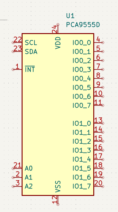
Since I would run out of GPIO pins if I gave the number connectors I wanted their own EN pin and since I already had an I2C bus, I decided to use a I2C GPIO expander to handle the EN pins. This also set my number of expansion slots at 16. (theres literally no reason to have this many lol // dear god I could put them in a matrix to have 64 slots)
Time spent up to this point: 2h
I then wanted to find a component that would work well for connecting the keyboard to the modules. I really wanted to have magnets integrated into the components to make hot swaps easier. While I could have used a 6 pin USB connector that would have looked pretty lame and someone would have plugged a USB drive into it hoping it would have worked. I actually spent a couple of hours on LCSC going through quite literally every single 5 pin 3 pin and 4 pin magnetic connector but all I found was this component here:
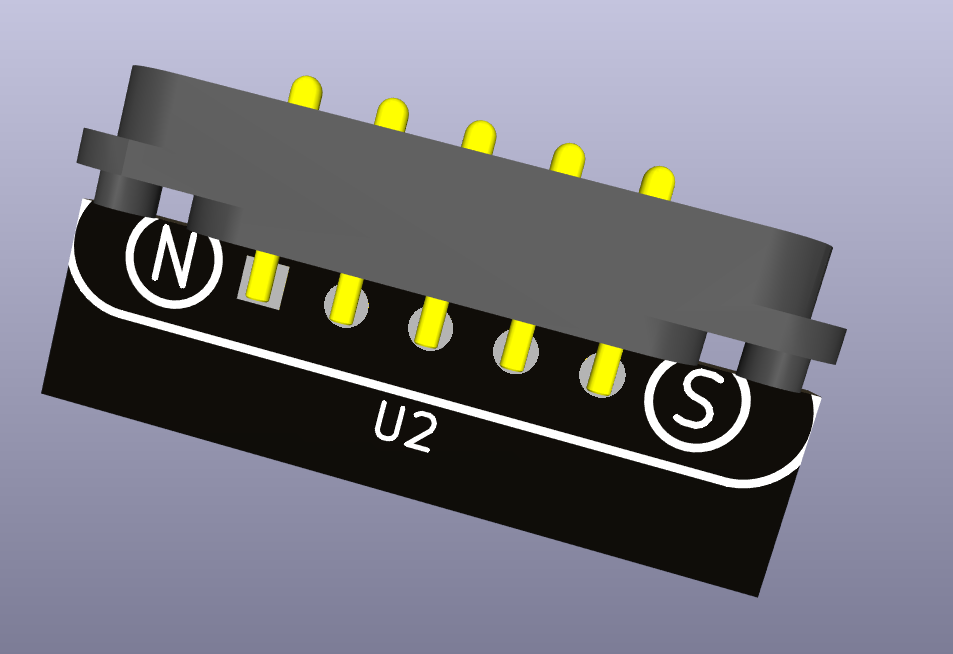
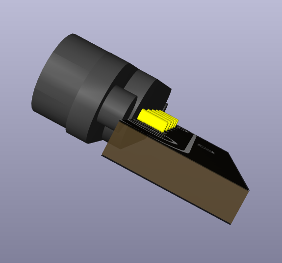
(I manually rotated it onto its side)
Anyway I thought this would be too sketchy so I left that idea and went to the good ol reliable:
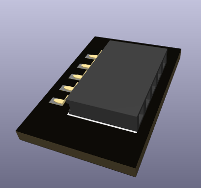
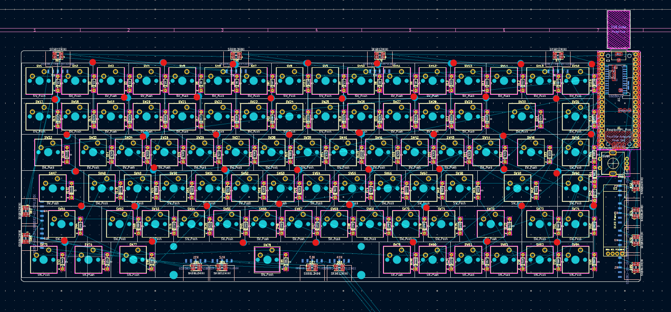
After I figured out my connector footprint I put together a layout for my PCB (w.o. LEDs):
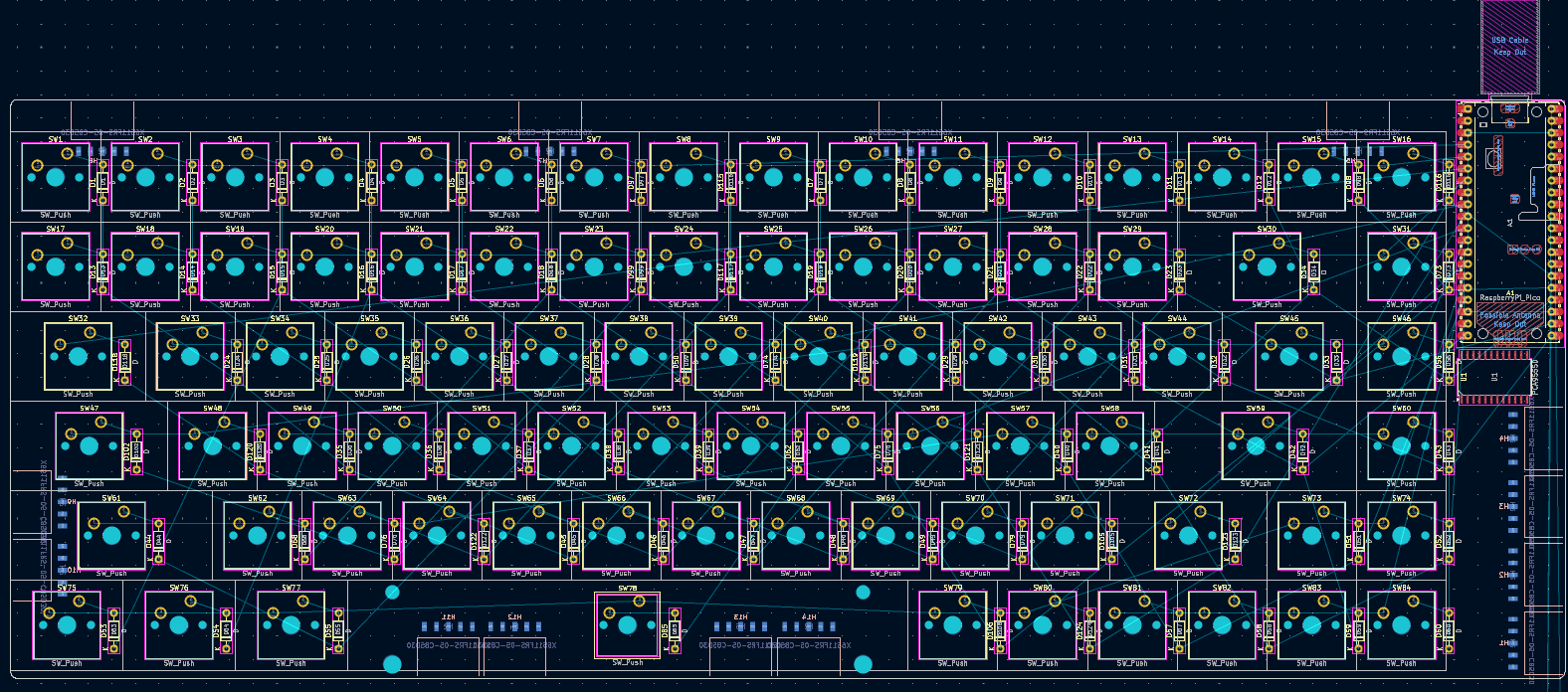
Time wasted on connectors: 3h
June 5th: Laying out LEDs + Encoder and OLED
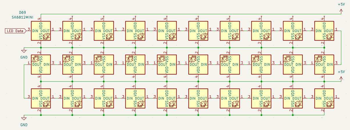
Today I layed out the LEDs into my PCB as well as adding an Encoder and an OLED. I started the LED placement with the 14 LEDs that would act as status LEDs for any connected module:
I also added even more LEDs that I would place around the keyboard and structured them into 2 data lines (I am hoping this makes programming the specifics easier).
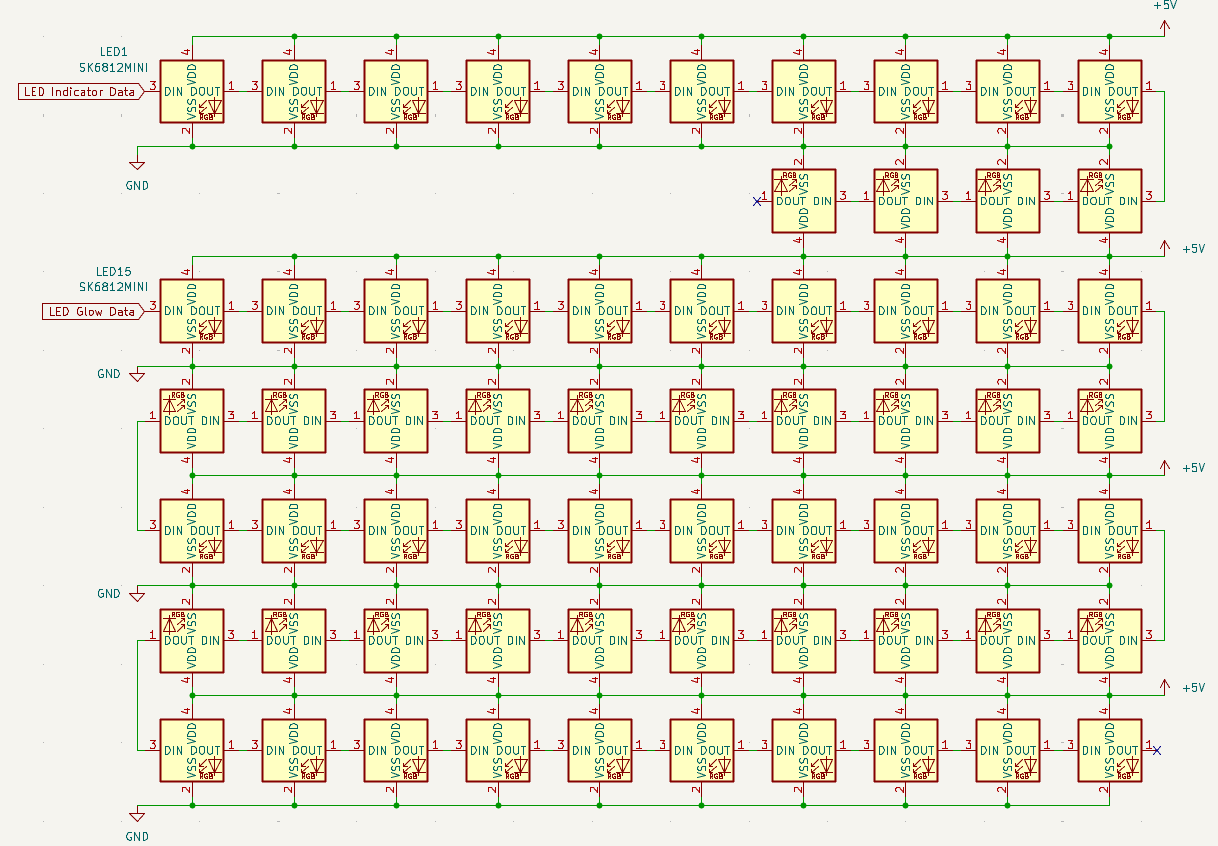
After that I wired up all of the module slots in the schematic:
Then changed it to have better formatting:
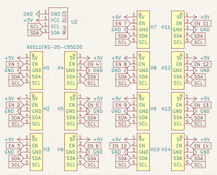
And that finishes the schematic:
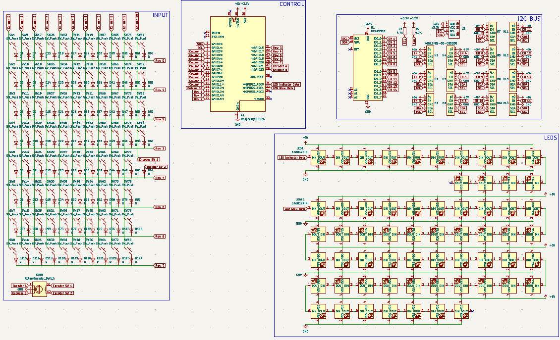
I then counted the spaces for where I wanted LEDs to go (checked it twice lol so 2 dots):
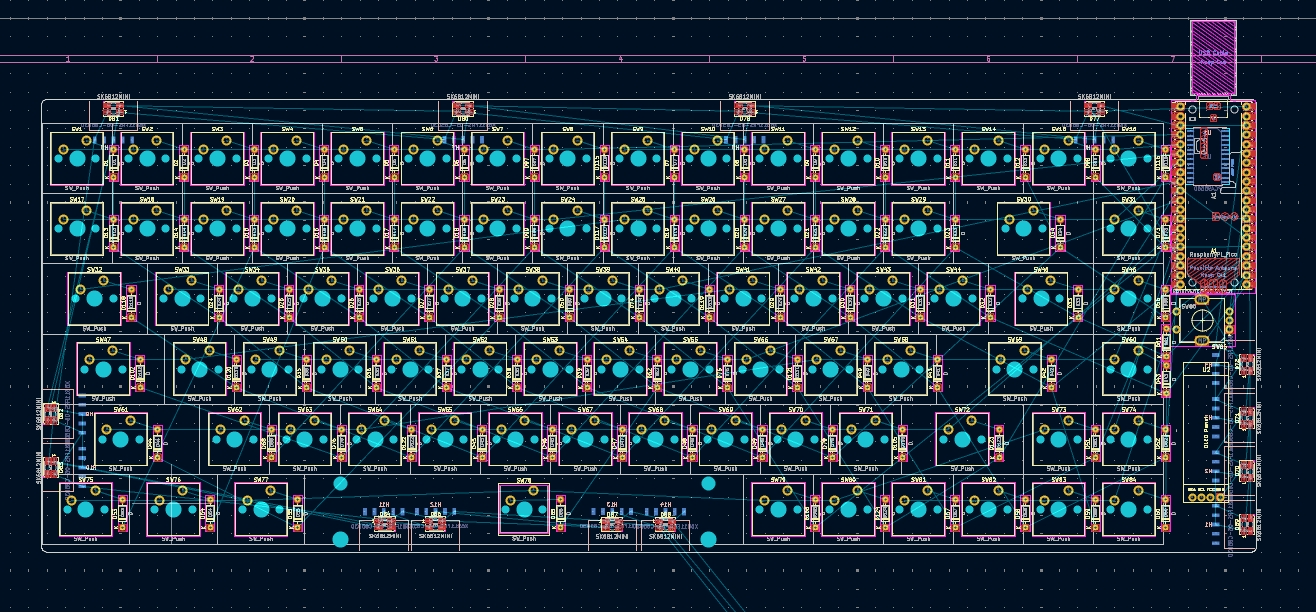
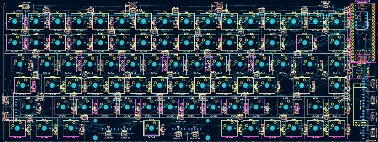
After that I added in all the keyboard LEDs:
Total time spent: 2.5h
June 6th: Routing Time
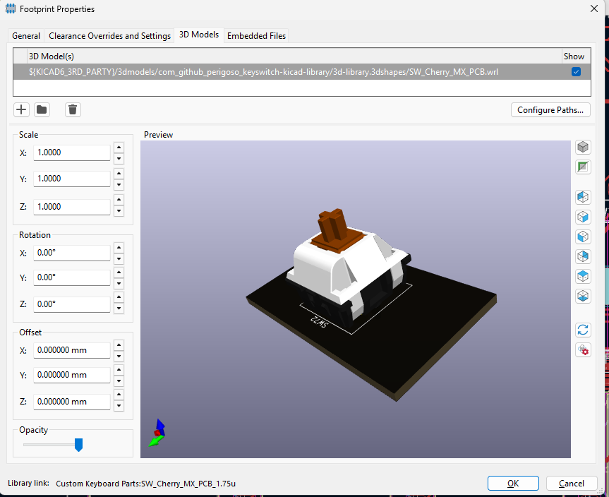
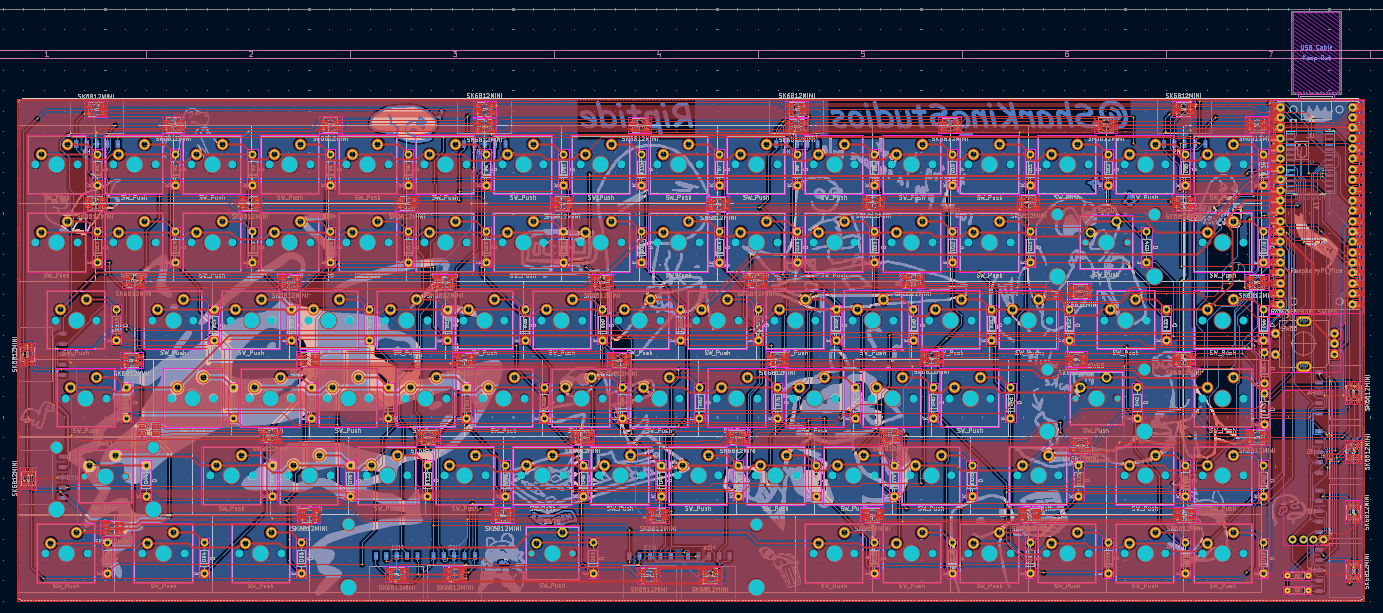
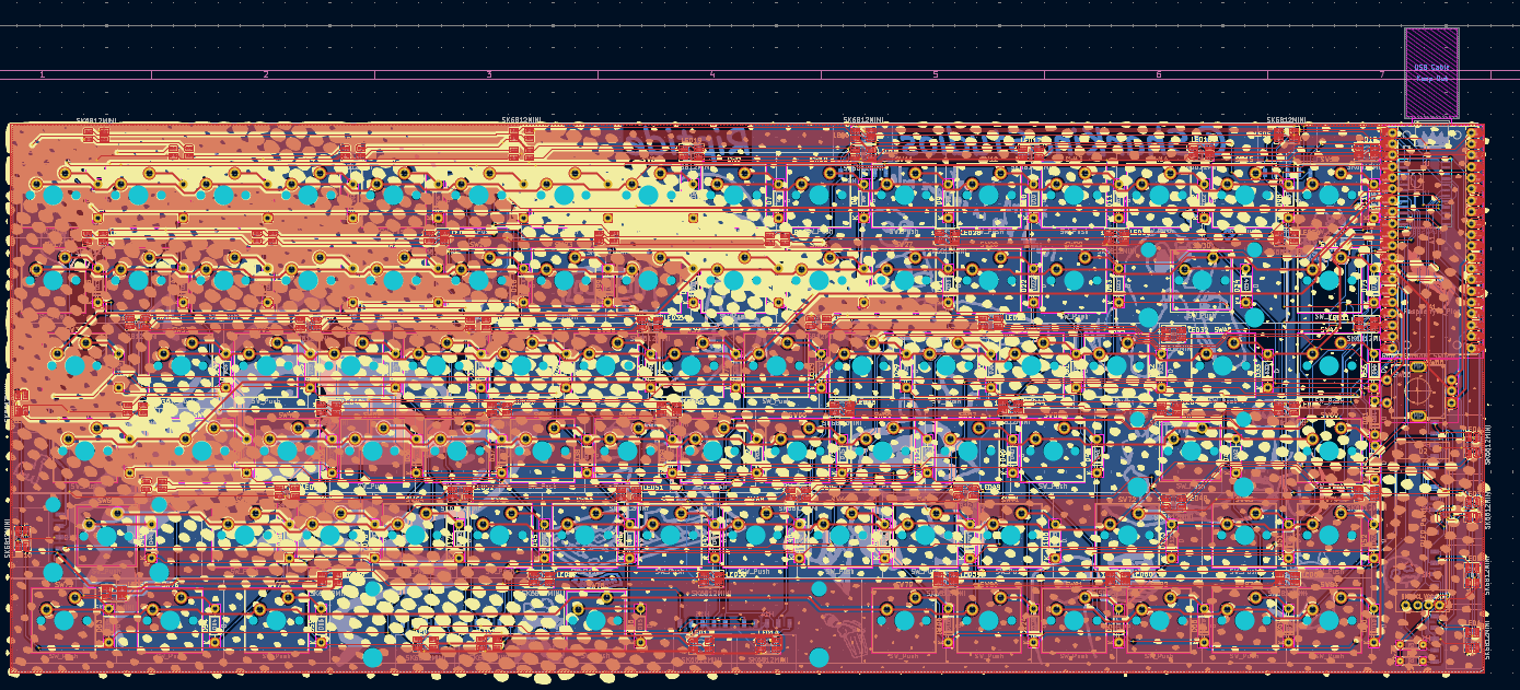
I started routing today (yippie). I tried using .6mm to route everything then just switched back to .4mm lol I also added some 4.7k pull up resistors on the I2C lines because I forgot those earlier. After this I also added every 3D model. (Cant have a bare render right??)
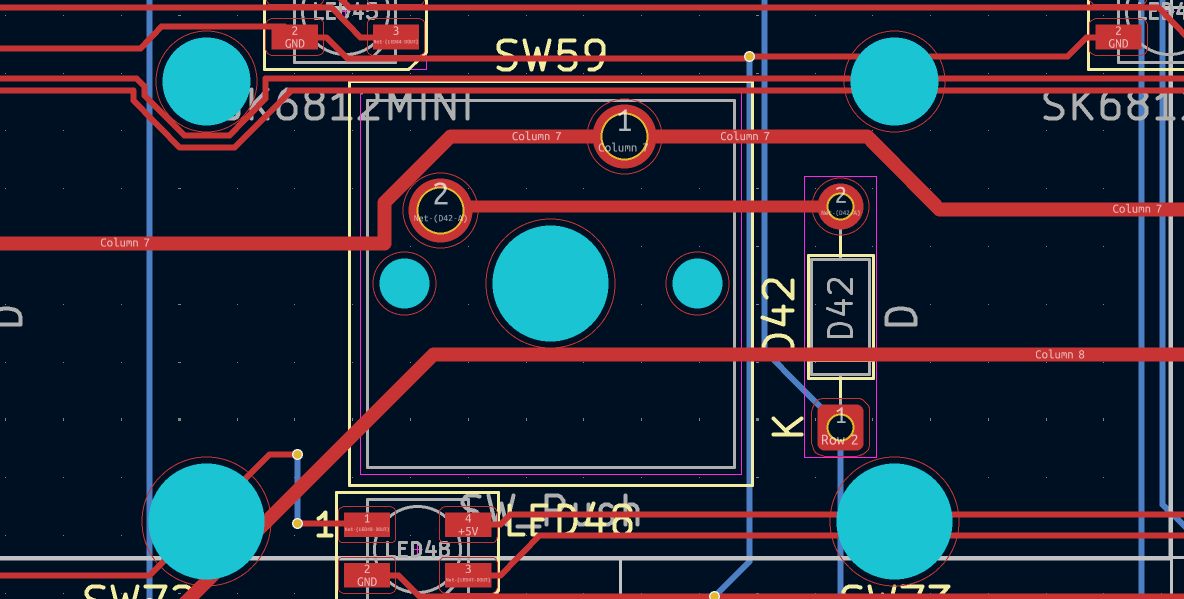
After routing the entire thing I realized I forgot to add the all important stabiliers on the shift key, enter key, and backspace. When I did add them I needed to redo some wiring but they also interfered with multiple items including various LEDs and some of the expansion ports:
After I finished all of the issues with the PCB I finally got this:
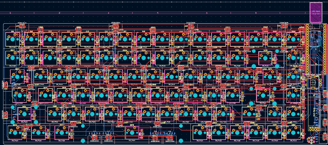
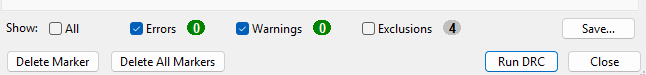
Total time spent: 7h
June 24: We are so back! (From Undercity lol)
Undercity was super fun!! I loved helping run such a big event! Anyways, this is me after I finished up with the rereviews that were waiting for me during undercity...
Today I worked on the PCB art for the keyboard. I got this nice wavy pattern in for the front:
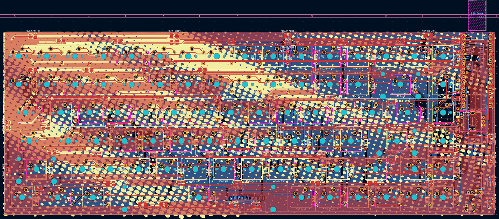
and used my collection of silkscreen art for the back (mostly from rawr.hackclub.com):
Final product:
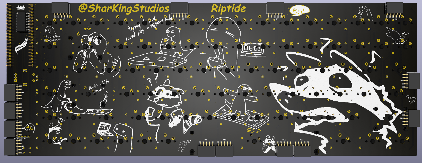
I even totally got no DRC errors!!

Total time spent: 2.5h
June 28: CAD time
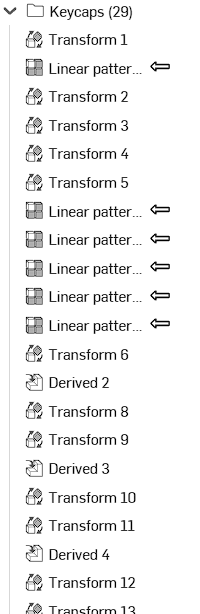
Today I got my Onshape set up with files from my KiCAD and started work on the case. I spent an especially long time working on getting every single keycap in the CAD. (To make it look awesome ofc)
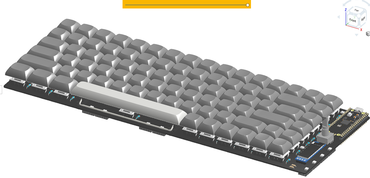
After I got the keycaps in place I created a keyboard plate as well as the 3D printed top section that would hold it down. I wanted to use a similar style to my Splashpad and keep the awesome looking Orpheus Pico visible.
I didnt like the way it was turning out so I changed it to this:
I then finished the day by adding bronze standoffs that I had lying around from a previous project and a 18ga steel bottom plate:
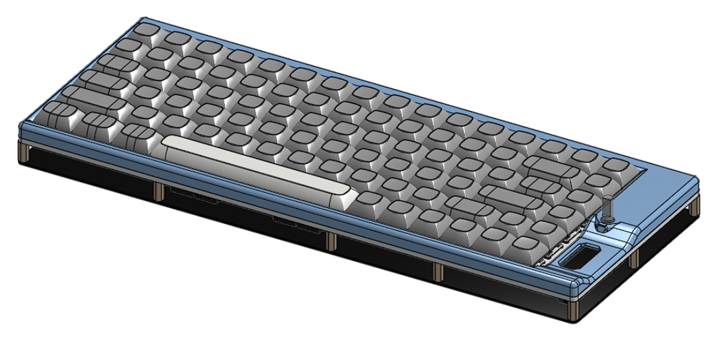
Total time spent: 5h
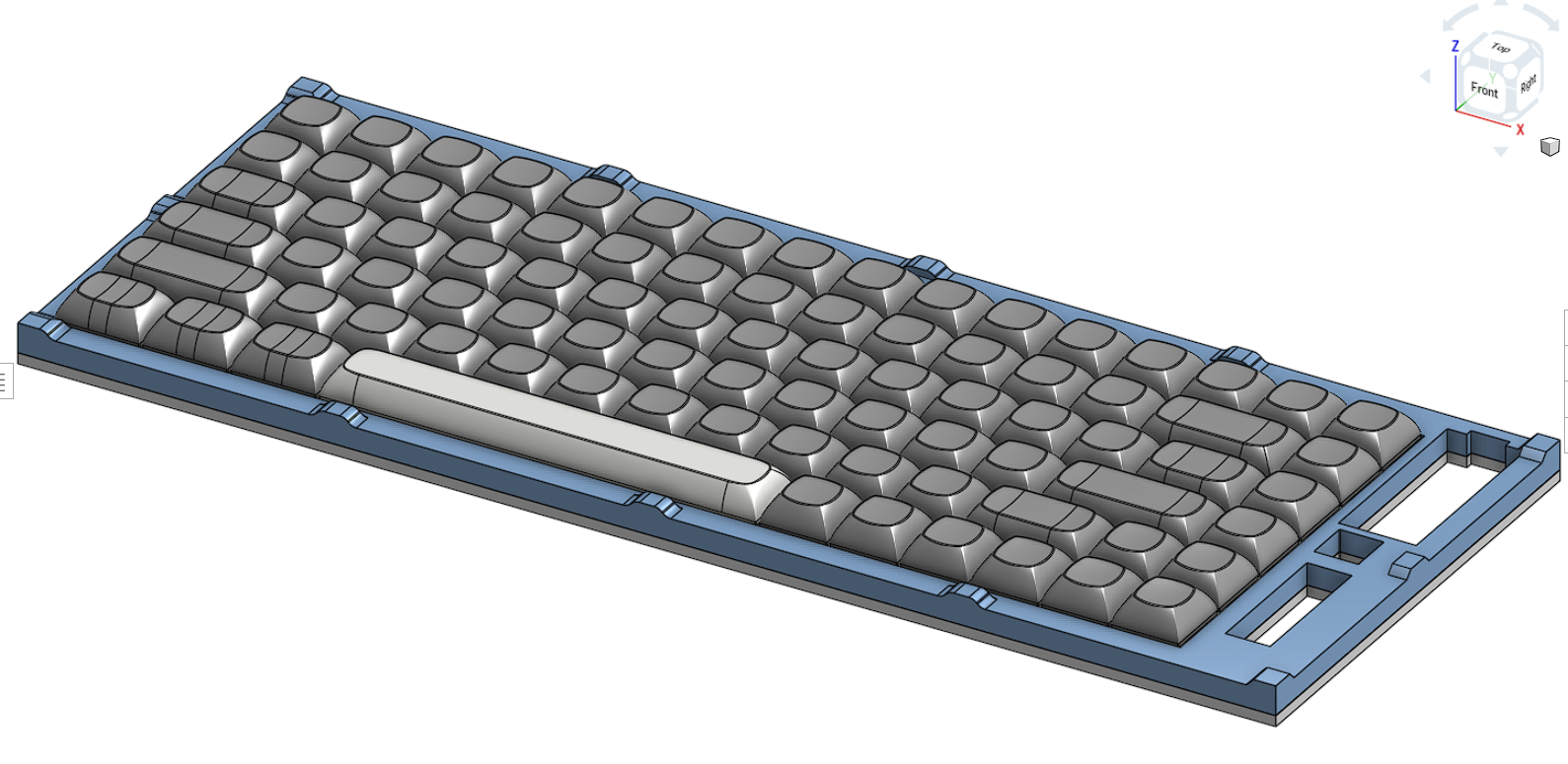
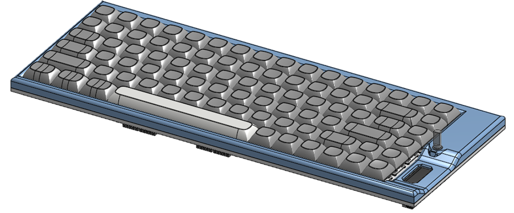
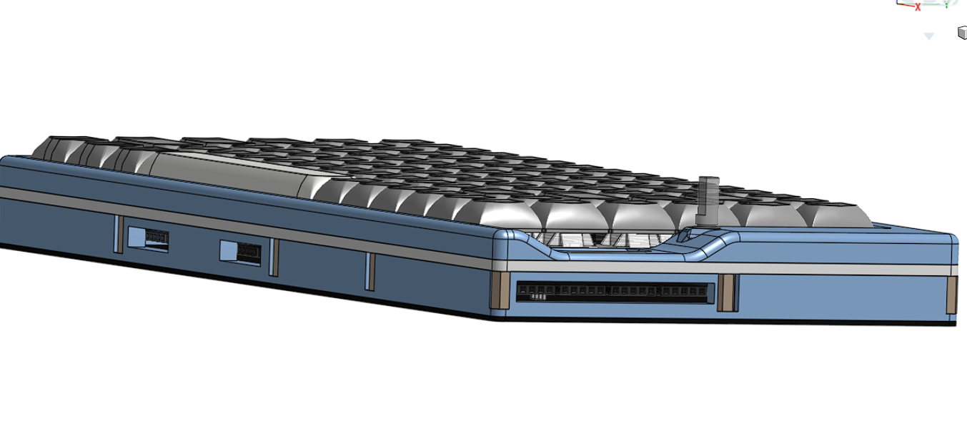
June 30: Finished the CAD
Creating the middle section was kinda the hardest part of the CAD. Its also what really pulled this keyboard together (almost literally). It does look truely awesome though.
WIP:
When making the isogrid pattern I followed the same kind of procedure I used with my Splashpad. I finished it up by changing all the keycaps to the colors they would be with the set I intend on using.
Final CAD:
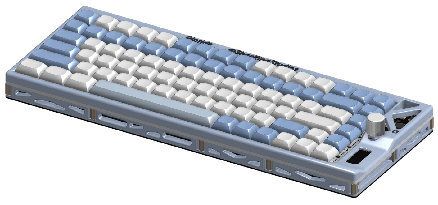
Total time spent: 6h
June 30: Magic Keyboard Firmware
When I had made my Riptide hackpad, I used KMK firmware for its ease of use as I thought it would be easier. After I built it, I have been having significant trouble getting it to work. Instead for the keyboard I have decided to use QMK firmware.
Making the firmware actually wasnt as hard as I thought it would be since I already had Ubuntu Linux installed in my terminal.
I did experience a number of errors:
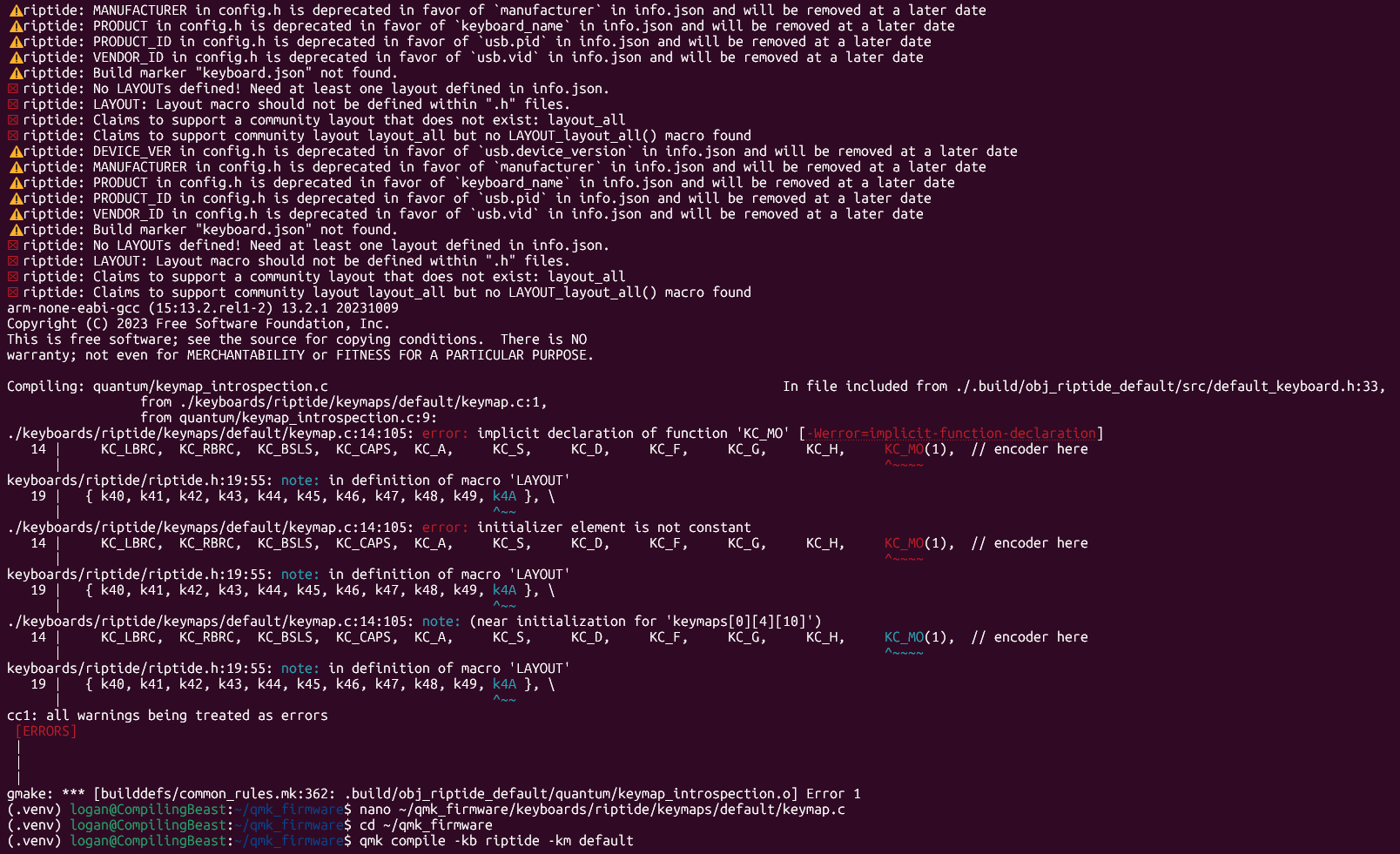
But I was able to get it compiled:

Total time spent: 1h
June 31: Blender my Glorious Goat
I dont know blender but I really want some nice visuals. Time to learn it ig.
It actually wasnt too bad, except how after I exported from my CAD the keyboard had a bajillion assigned materials that I had to go through. The extent of my lighting knowledge is to have a Key, Fill, and Ring.
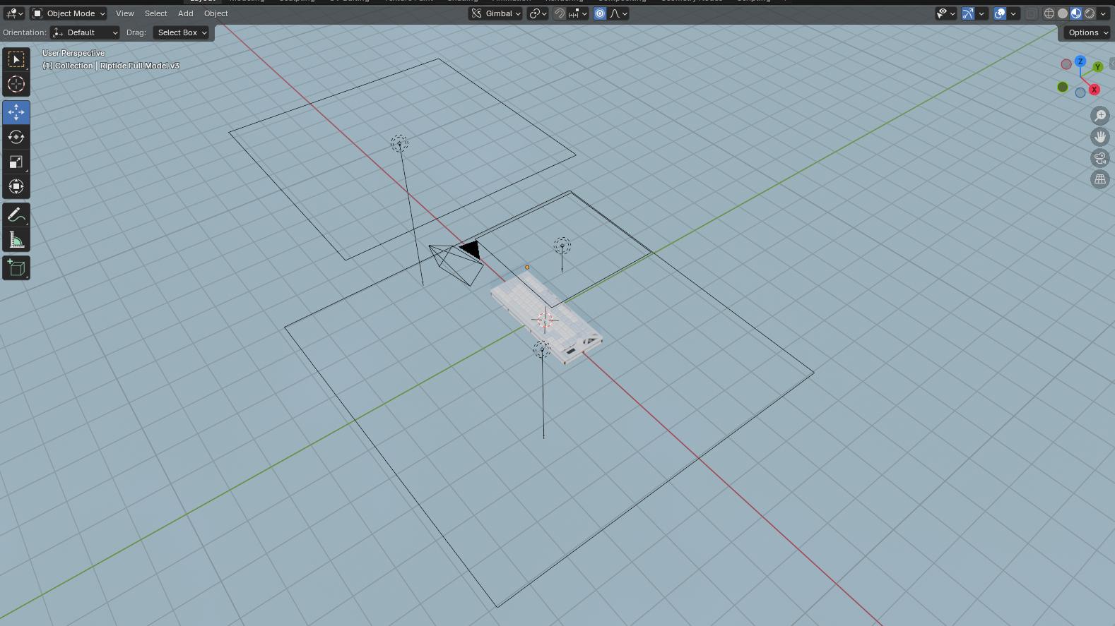
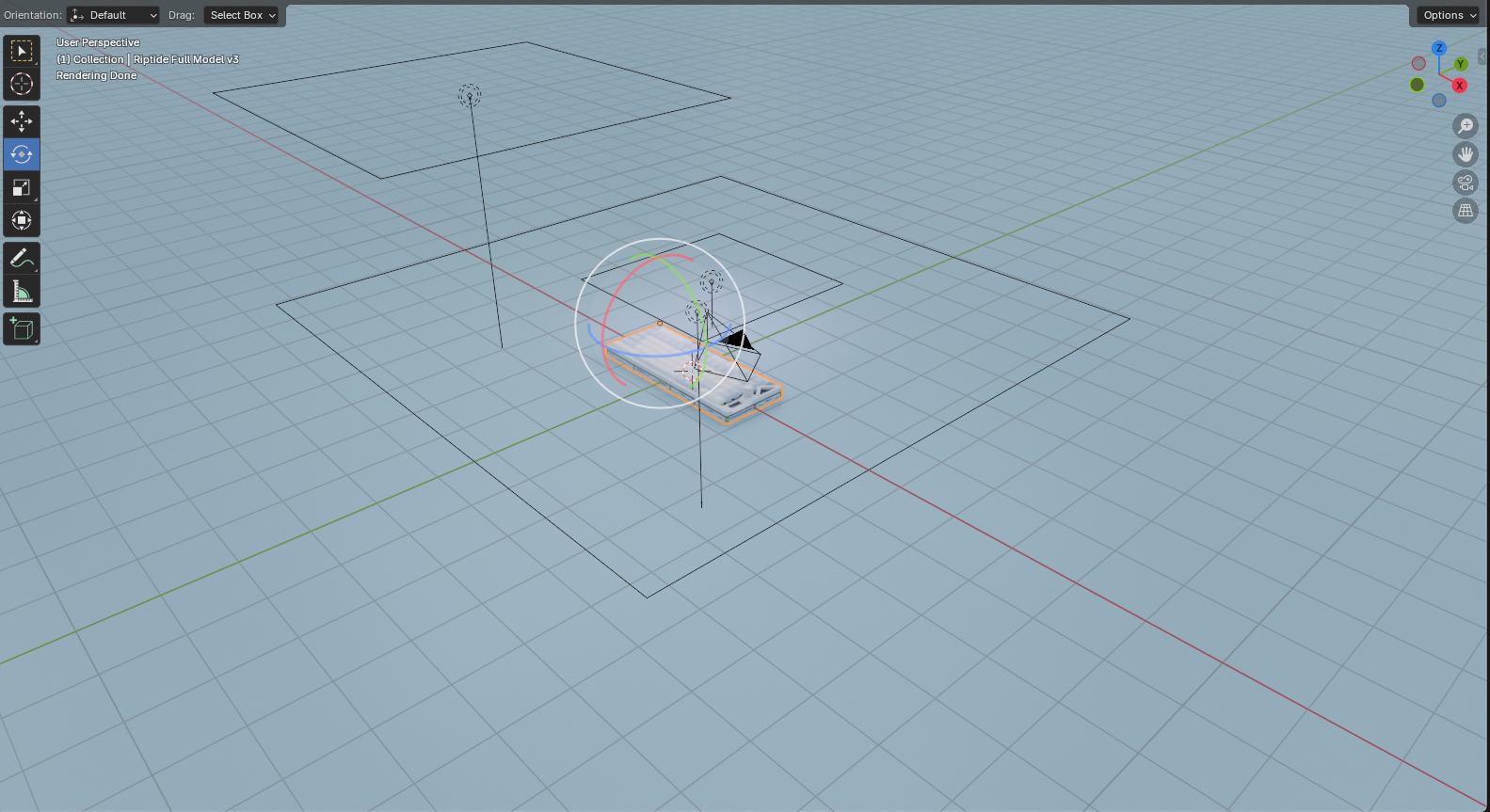
Working Screenshots:
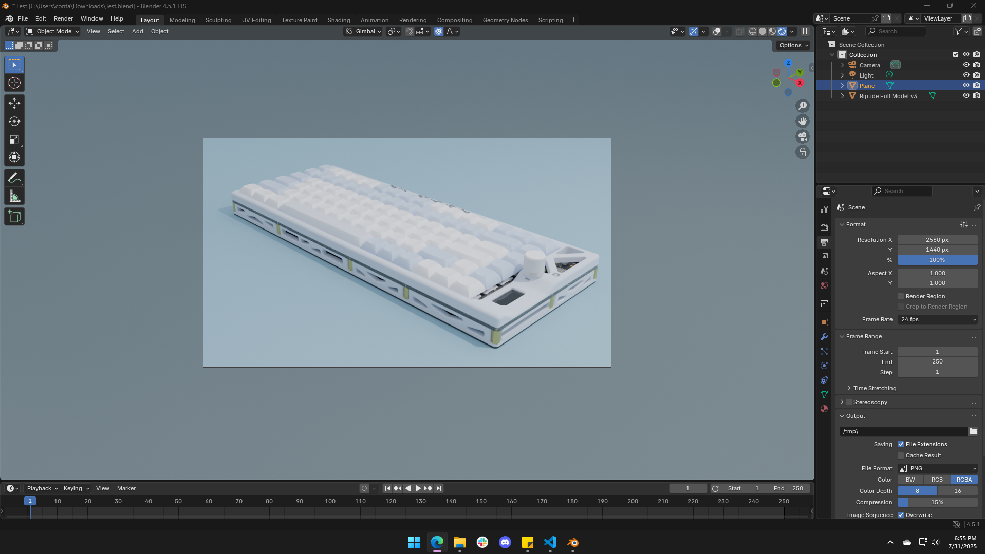
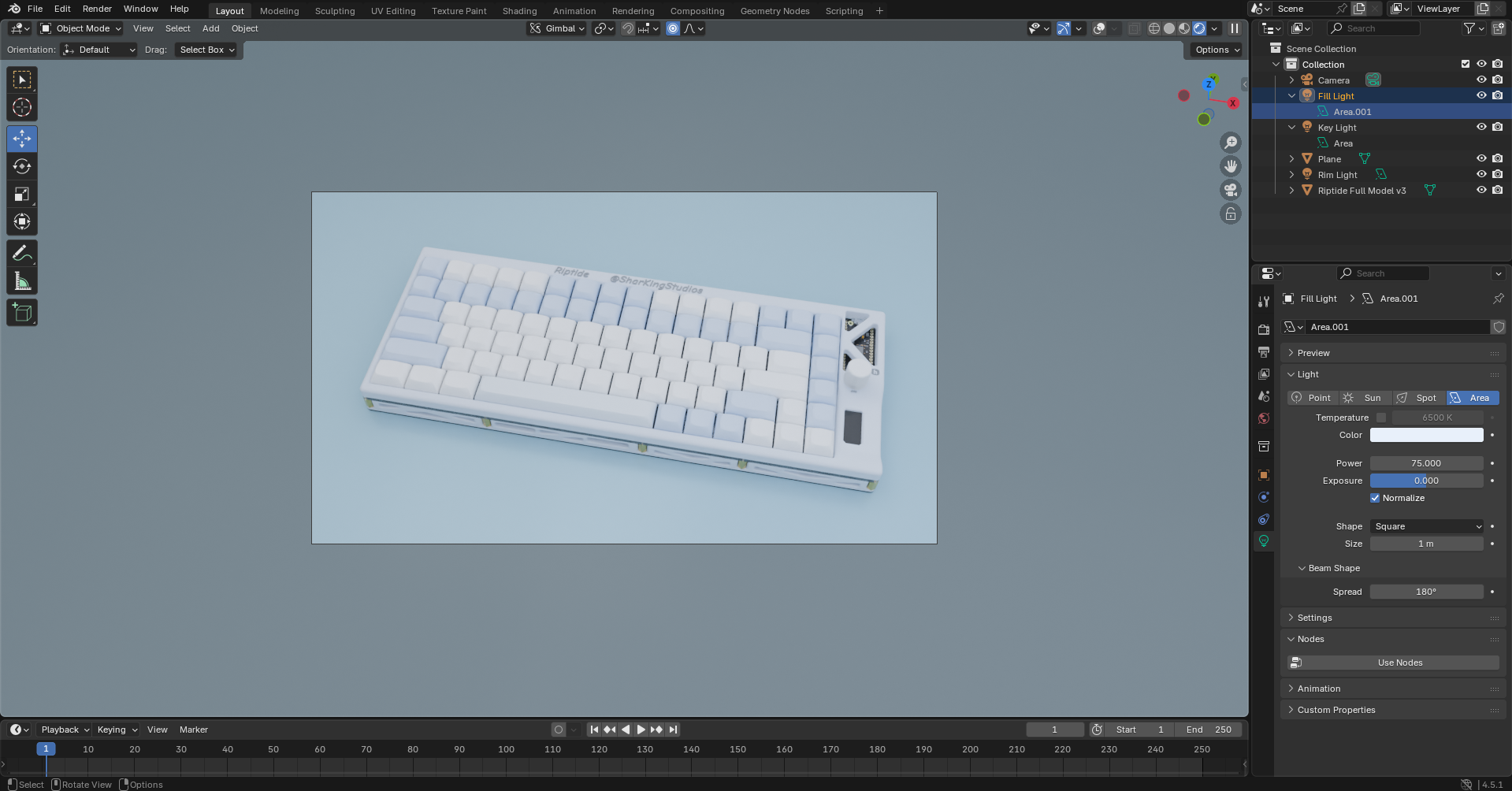
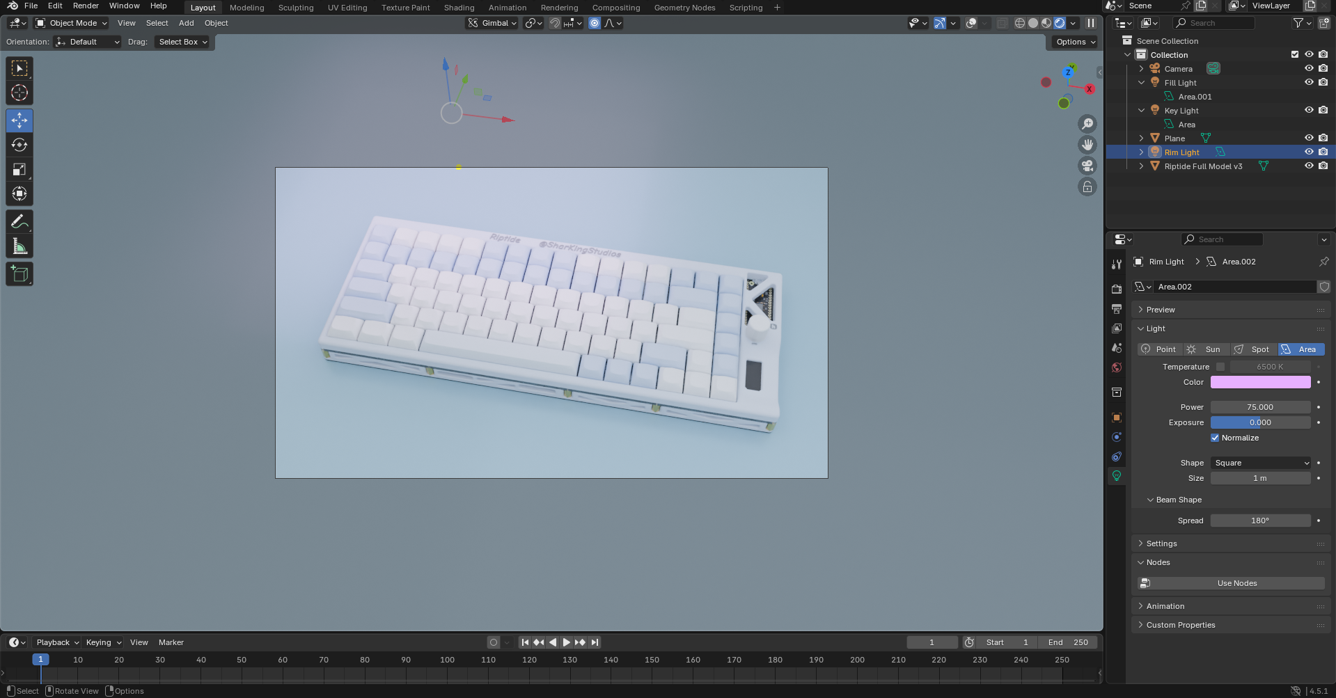
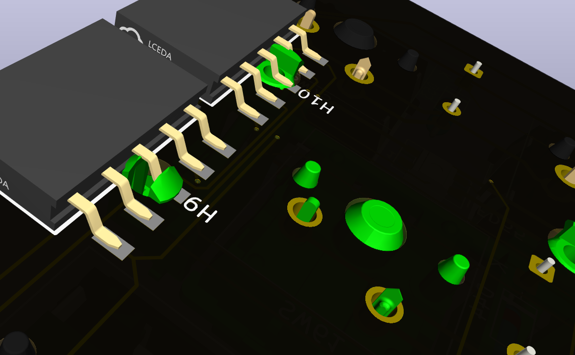
I was able to make some totally awesome looking renders:
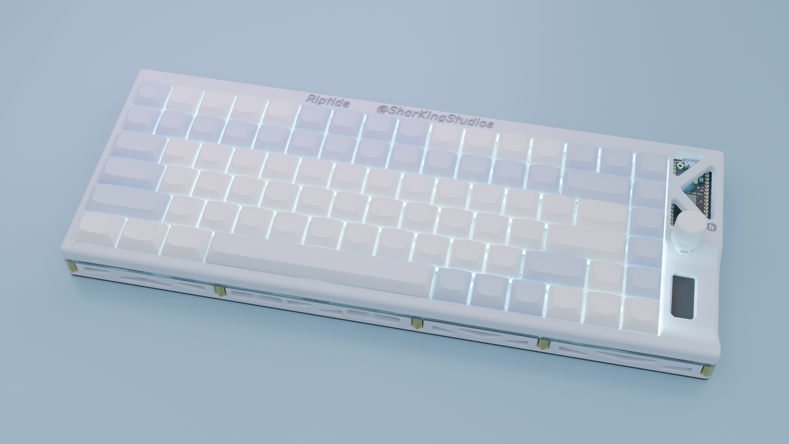
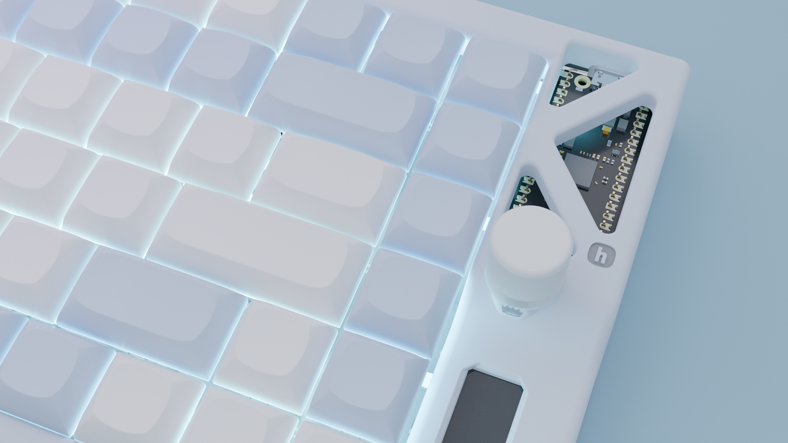
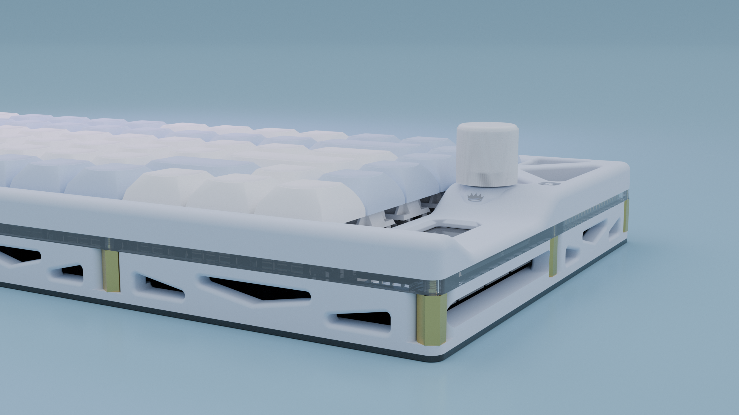
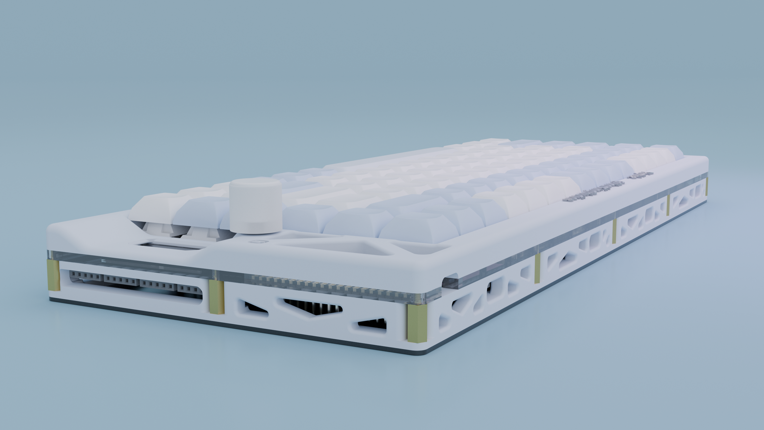
Total time spent: 4h