
Total time spent so far: 45hrs
note: the information in this file is not final and binding as this file is ment to be how I ended up with the final product, checkout README.me to know the correct information.
First week of June: Research
Watched hell lotta youtube videos to get a basic idea and all of what i wanted to make and how i wanted my keyboard to look like
I decided to go with a TKL Mechanical Keyboard layout with some customisations
| Layout |
|---|
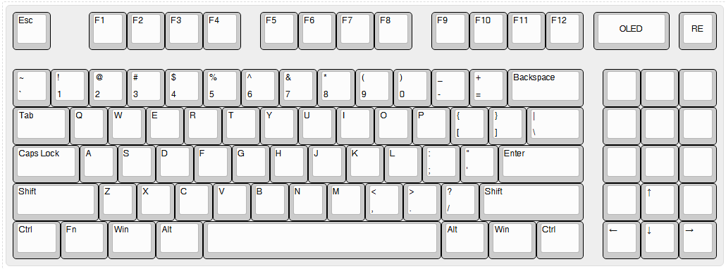 |
The keyboard is gonna have
11 macro keys (basically integrated macropad), aRotary Encoder Switch E11, and a0.91inch OLED Display 128x32and is gonna useSTM32F411CEU6 Black Pill Boardas its mcu.it was REALLY painful to find out symbol and footprint of
STM32F411CEU6 Black Pill Board
Time spent: 6hrs
08th June: Got started
| Basic Schematic |
|---|
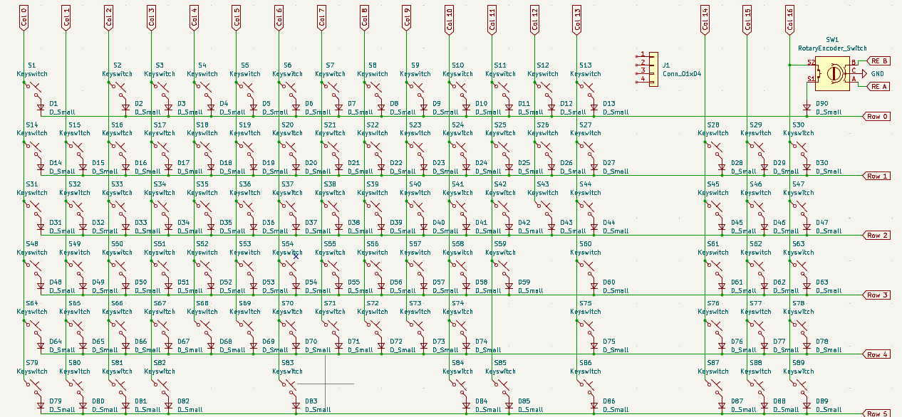 |
Got done with keyboard matrix and wiring
Found out
STM32F411CEU6 Black Pill BoardonEasyEDA, converted.jsonfiles into symbol and footprint of it
Decided to make the keyboard Low profile since i dont really like the chunky ones(yet to finalise the switches and keycaps)
Time Spent: 5hrs
9th June: Made the BOM
I was tryna finalise the components and things which i was gonna work with but then found it difficult to keep a track of the money that was going into every component, so i made a BOM in
README.mdfile, its currently at its second draft and is going to be updated throughout the projectI couldnt find a low profile keyswitch which was available in my area and was in budget, spent like 2hrs on it, then researched a bit about
cherry mx switches, decided to go withCherry MX Silent Redbut it wasnt available in my area so then i asked for help in#highwayand ended up withGateron EF Curryswitches since they are linear and LED compatible (im planning on adding LEDs to my keeb too)The symbol of
STM32F411CEU6 Black Pill Boardwasnt symboling (basically it was very buggy, like smth was wrong with it ion know what) so i chose to go withRPI Pico(the reason why i wasnt using it before is cuz its hasmicro USB interfacewhich i didnt want to use in my keyboard but however had to cuz I ran out of options)i was indecisive if i was gonna handwire my keeb or make a pcb, so i ended up watching 3 to 4 videos about handwiring but then decided to go with the pcb
Spent hell lotta time making the BOM and finalizing the MCU
to do list for tomorrow - [ ] complete the schematic
- [ ] add a GPIO expander to the rpi pico
- [ ] wire it all
- [ ] add and setup leds
- [ ] complete the pcb
- [ ] layout it
- [ ] add some cool custom silkscreen art
- [ ] add the gpio expander used in the BOM
Time Spent: 7hrs
06th and 07th July: major updates
oh boy oh boy oh boy finally after like a month or sum of break im back!!!!!!!!!! i had my exams going and i got distracted by some other things, anw but when my pcb for
#hackpadarrived it looked so cool that i got the feeling to continue the keeb again!!
we are back off VERY strong!! changes like: a whole layout change, sch done, pcb done and much more and feature changes has been made
| Final Layout |
|---|
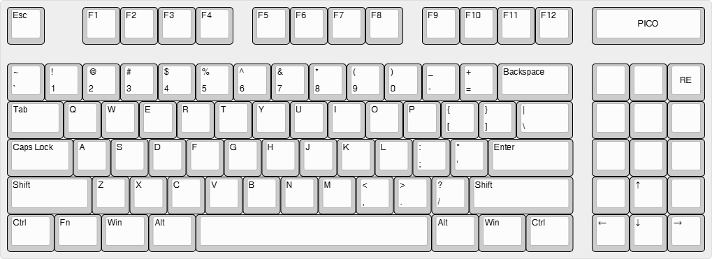 |
i originally thought of trying the double row method mentioned in the guide but it didnt seemed right for just one being short on one gpio pin and so i came up with this after like 2 or 3 layout variations
after brainstorming a bit in the slack with other ppl, i came up with this layout because i didnt wanted to use the gpio pins expanders as its too complex for me to understand
the thing(s) left now is the silk screen art and designing a case which should be done in a day or two (well hopefully)
Time Spent: 11hrs
30th and 30st July: last part
after procrastinating for a whole month i finally decided to get started and done with the 3d design of the case, designing took around like 10 to 12hrs and it was really hectic as i dont have much exp with 3d designing but still i was able to make a good case for my keeb also the rendering to take photos was so damn time consuimg cuz of like models of 80 keys in the file along with other things like the pcb model, rpi model the app kept on crashing and the rage bait was like 100000/10 fs. stil managed to get good render photos for the readme.md after a very long work to get the app working
| case |
|---|
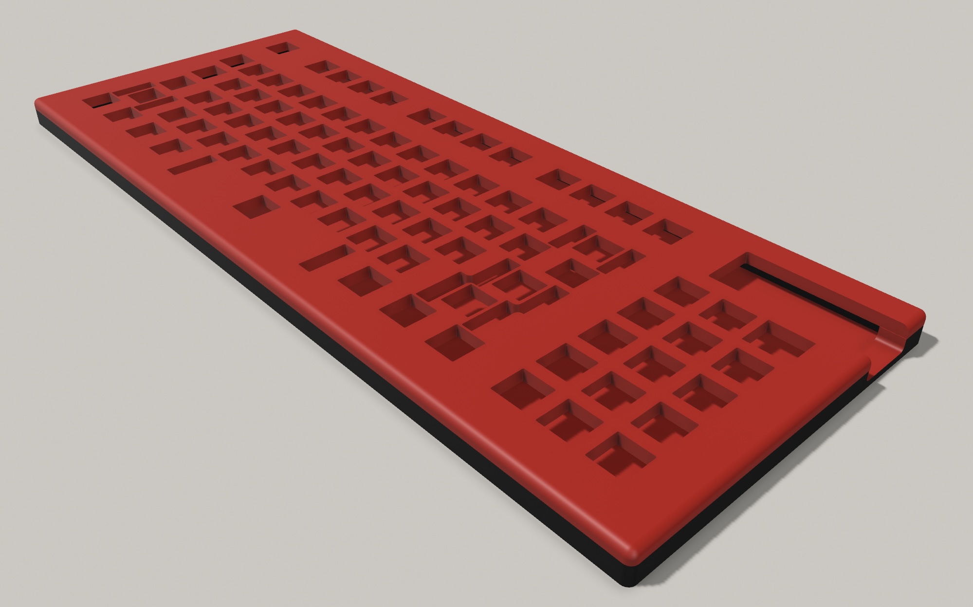 |
*there are more renders of the case in the README.md
i also updated the whole bom with the revsions and made the README.md file
Time Spent: 16hrs