
Floppy Square
A flappy bird-like game on a tft display with orph pico
FULL TIME ESTIMATE SO FAR: 9h55m (if I didn't forget how math works)
July 31st morning: Started the project, research
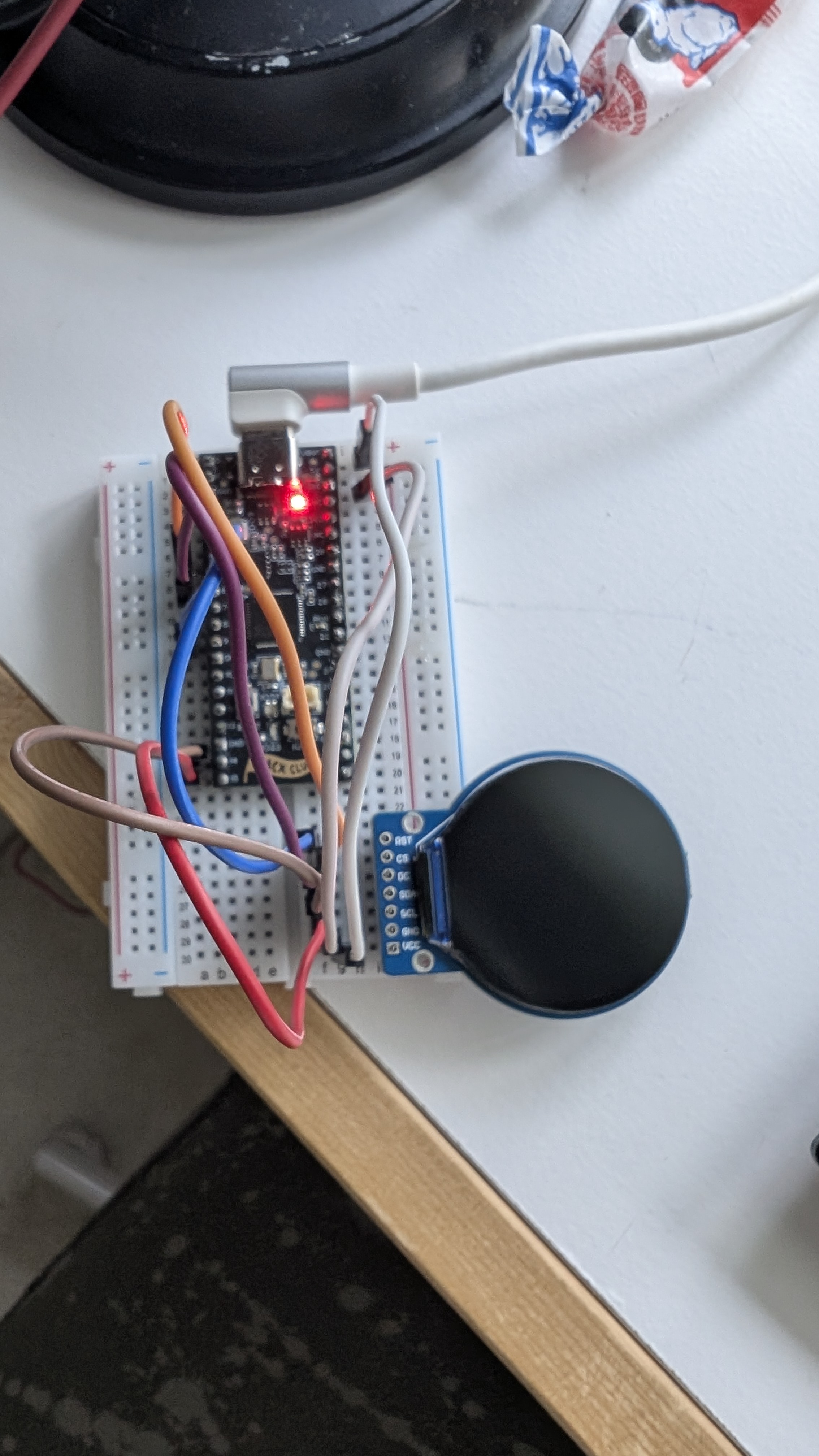
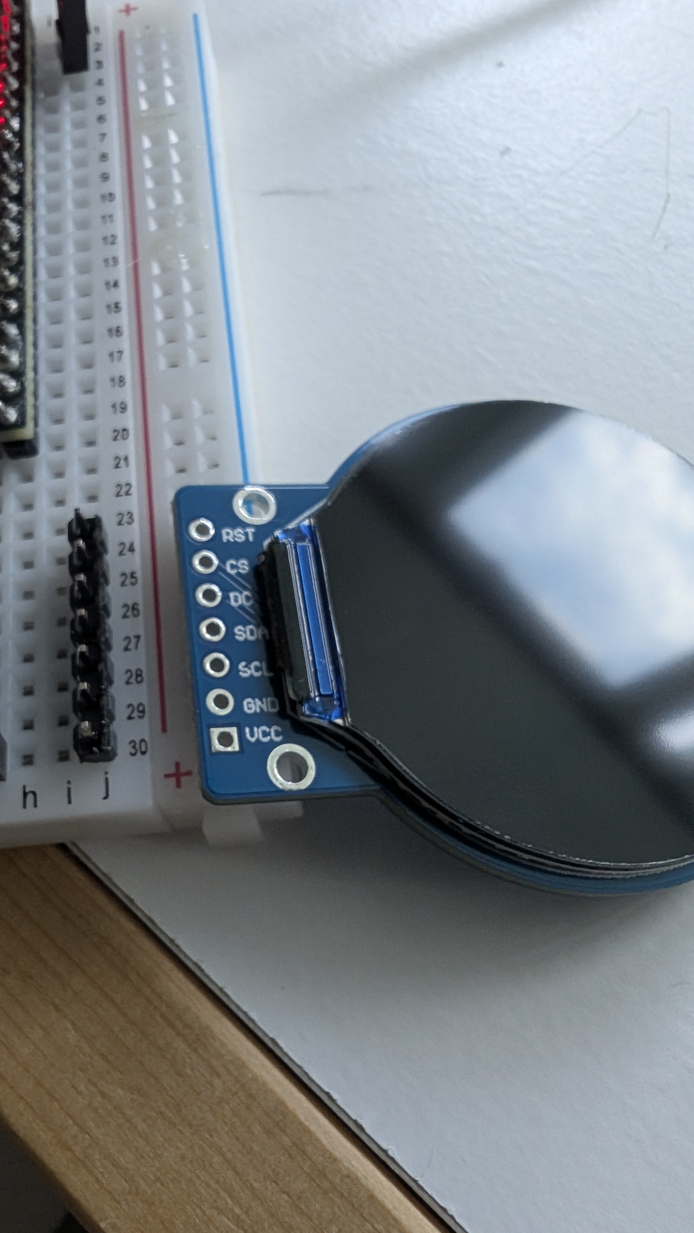
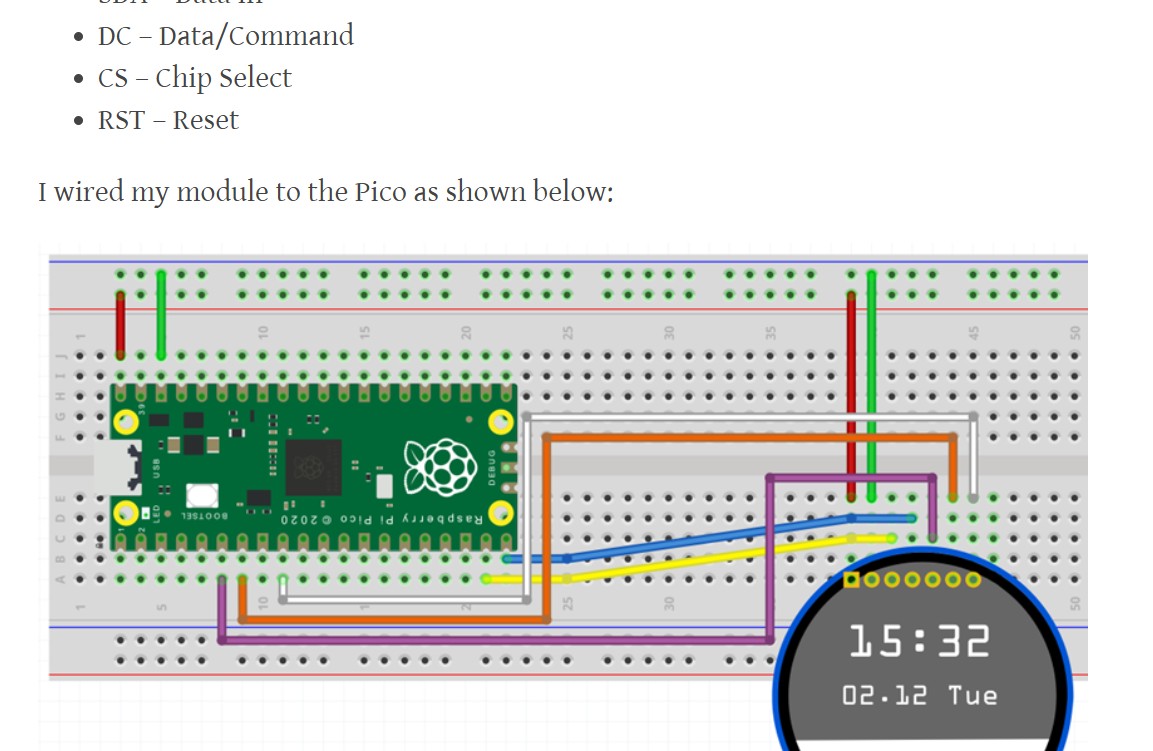
So I started working around 9am ish, and came up with an idea for a project: A simple flappy bird game on a round display I had laying around. This was quite out of my comfort zone, as I had never used this kind of display before, and although I've had it for some time, the first time I ever saw it in use was at undercity (I believe it was the same model but I may be wrong.) on the Minion robot. I went ahead and started researching how to even go about connect the display, and after some trial and error, I came upon this article which shows how to use it in micropython. I was originally thinking about using circuitpython, but for now I have opted to follow the instructions and figure out the display. So far, I have the test code and I have wired everything up with my Orpheus pico. I haven't actually tested it yet, as I haven't soldered the display yet. Will do that now. Wish me luck!
Next steps:
- solder display
- schematic
- add buttons
 Total time spent: 2h50m
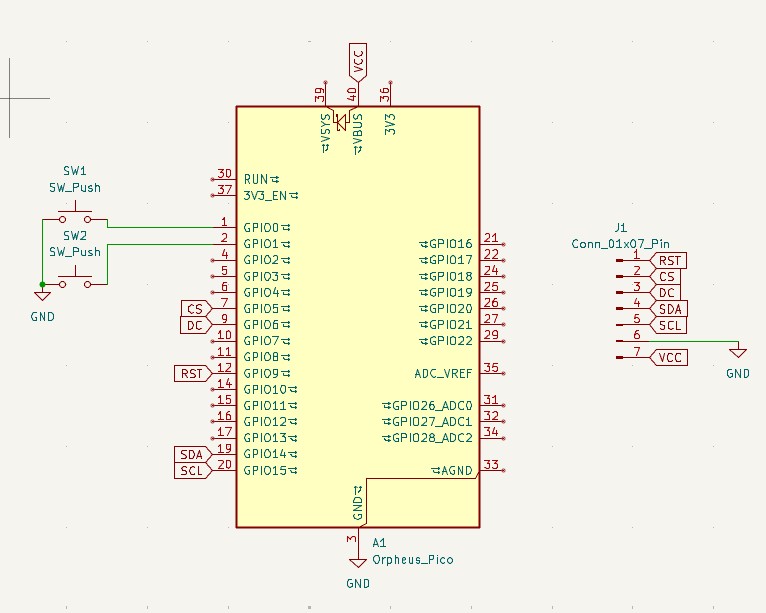
July 31st noon-ish: Working on schematic
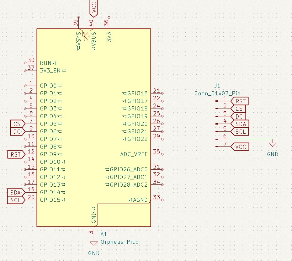
My father informed me I shouldn't solder anything without supervision (:skull::skull::skull:) so I was stuck making a schematic on KiCad. I didn't make a PCB yet because I'm thinking about using a perfboard (hope that's allowed...). I haven't decided what pin I want the button(s?) on yet, so the schematic is literally the pico with a 1x7 connector atm. Feeling kind of hungry so I'm going to go eat lunch.
 Total time spent: like 25m :sob:
July 31st early afternoon: Wokwi
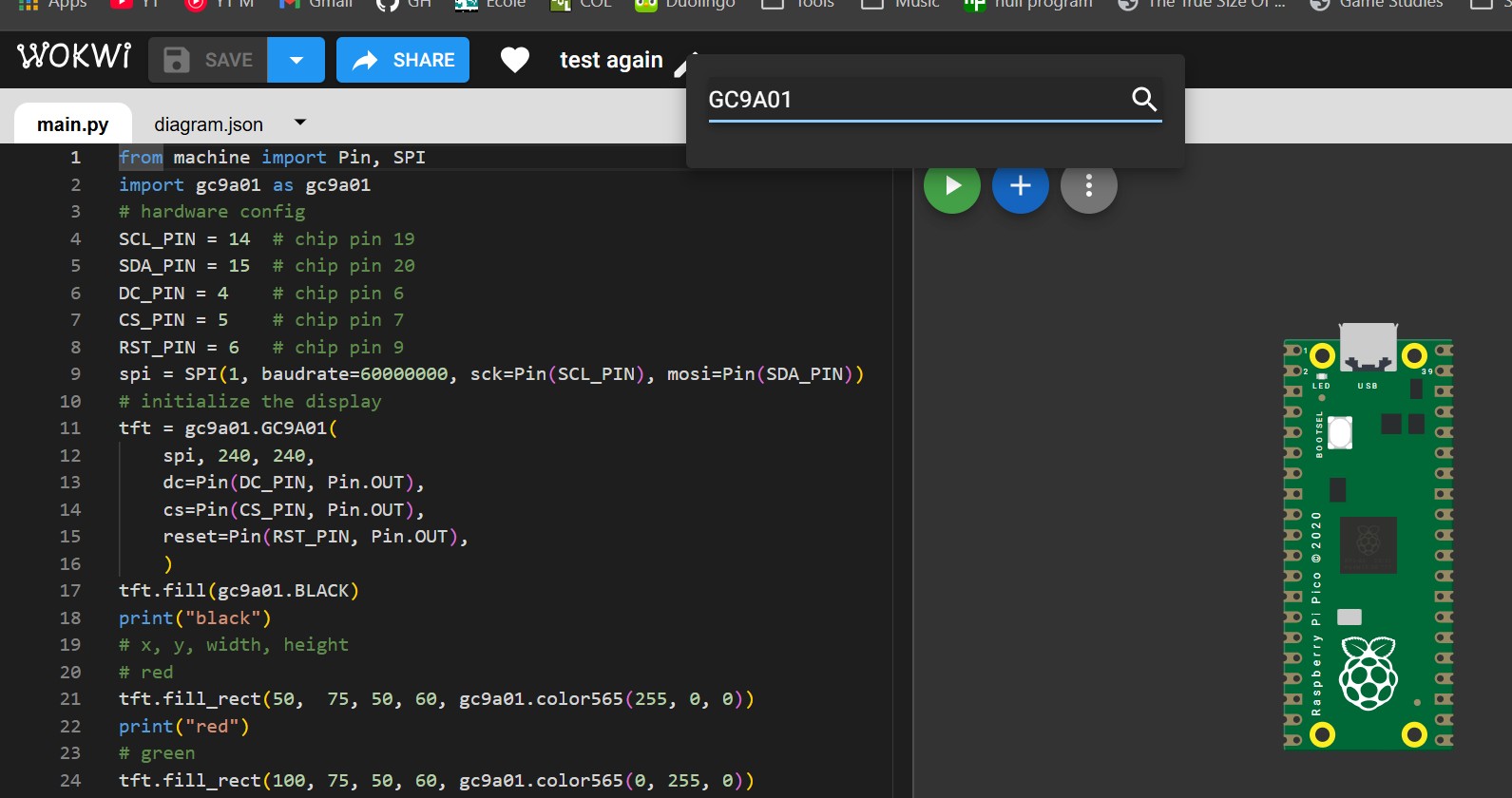
Ok lunch wasn't ready yet and it hit me that I could possibly try to test the code using Wokwi, but after about 15 minutes of trying to make it work I realised that there's no display component in wokwi and I gave up.
 Total time spent: 10m
July 31st after lunch: Pivoting and continuing schematic
So I decided that I would rather make something like the chrome dino or geometry game rather than flappy bird, but I don't want to change the repo name because I'm too lazy :skull:. (I wrote this previous section before starting the session)
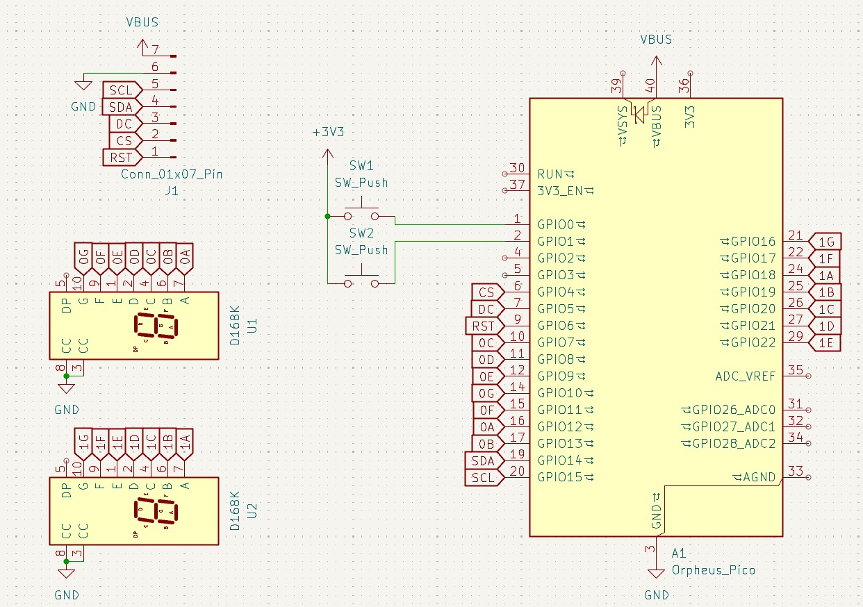
I continued working on the schematic and added two pushbuttons and two seven-segment displays. I will use the pushbuttons to control the game (1 will probably be play/pause) and the displays to show the score. After finishing and organizing the schematic (hopefully the last revision? :crossed_fingers:), I tried to wire up the circuit on two breadboards but realised I don't have enough jumper wires for both displays, so I left one unwired. I also worked on a test file for the display, and i'll port it over later. My mom's been home for about an hour now, so I can go solder.
 Total tIMe spent: 2h20m
July 31st afternoon/evening: Soldering
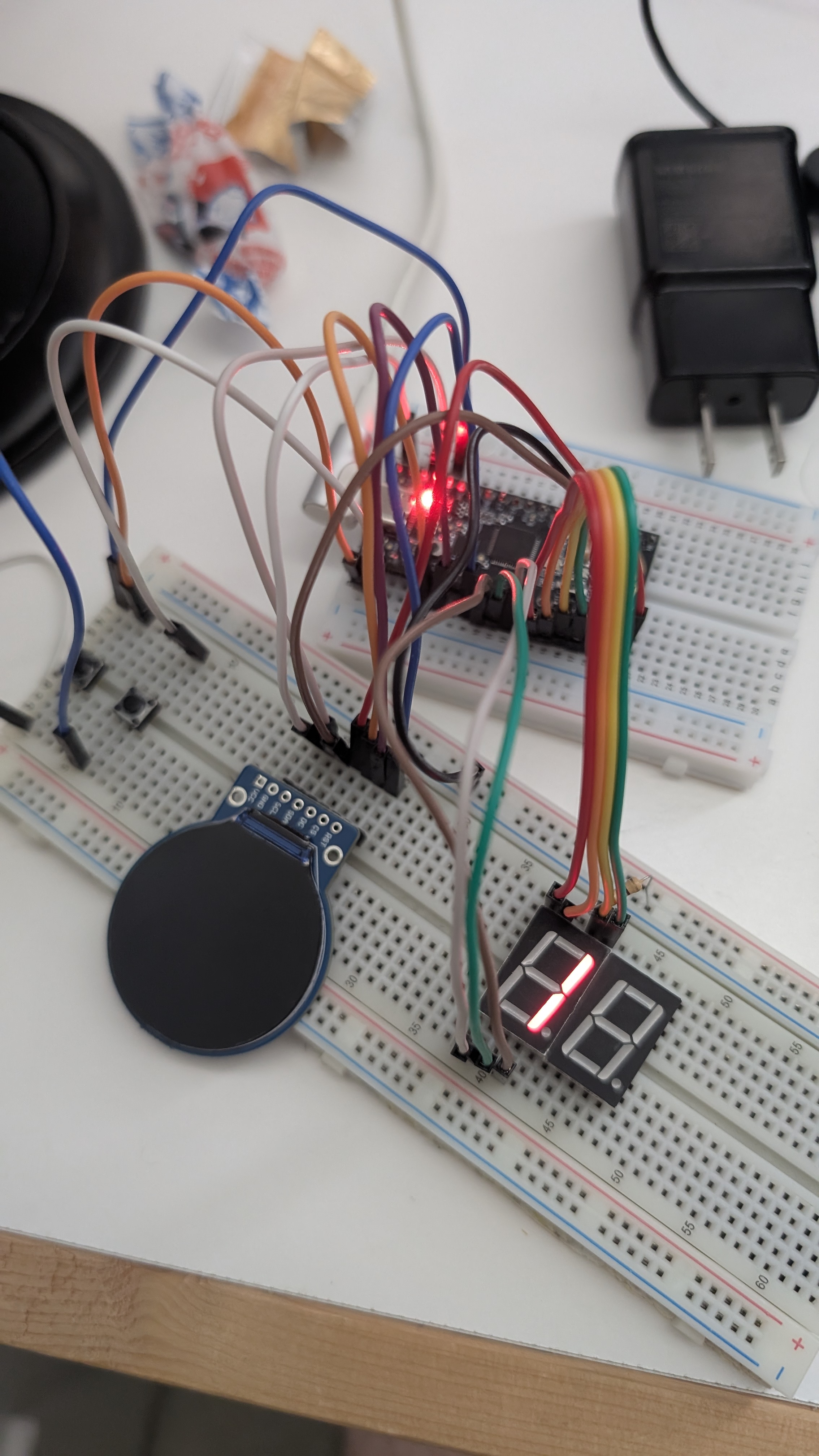
I soldered the display pins. It went quite terribly wrong :sob:... First of all, I soldered the GND and VCC pins together (because i'm stupid), then when i finally separated them, it still didn't work, besides the backlight slightly brightening. I hope this is just because of my soldering, and I will buy another display later with the grant money.
https://github.com/user-attachments/assets/8043284c-e6a4-4633-881d-286b245afca8
Total time spent: 2h30m :sob:
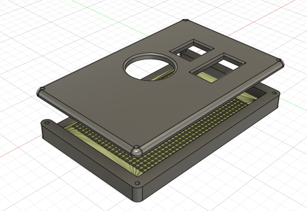
July 31st evening: 3D Design
I designed the case, trying to leave as much space and clearance as possible. I then exported f3d files and step files, available in the respective folders. I actually used the hackpad case design tutorial for this :skull:. I also updated the schematic to have resistors.
 Total time spent: 1h
July 31st night (RIGHT BEFORE DEADLINE): Firmware
I was stressing so badly for this part, and in all honesty, the firmware is NOT done. I implemented the display setup, button setup, and handling of the seven segment displays. I don't have any pictures of this unless you want screenshots of the code.
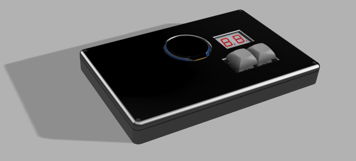
August 1st morning: 3D Design revision
I woke up today to a message from Cyao that I needed to add the components in the assembled cad file, so I went ahead and did just that :shrug: Idk what else to write here tbh. I found the models for the GC9A01, seven segment display, and Pico on GrabCAD, and I had the models for the switches and keycaps left from my hackpad design.
 Total tim espent: 40m