
Beach Rescue Drone
Autonomous Beach Rescue Drone & Dock
36 Hours - Part 1 (Drone)
17 Hours - Part 2 (Dock)
The Idea
Simply put: Create a prototype for an autonomous drone, that would be able to provide key first-aid rescue across Australia.
The Current Situation
Australia's extensive coastline is both a national treasure and a significant public safety challenge. The coastline is understandably a popular location for recreation, being a gem of the world. Despite the efforts of Surf Life Saving (SLS) services, many areas remain unmonitored or difficult to patrol. During the 2024-2025 summer period (December to February), 51 coastal drowning deaths were recorded.
Alarmingly: - 65% of these drownings occurred more than 1 km away from a patrolled SLS service
40% were rip-related beach drownings, with
- 27% of those involving bystanders attempting to rescue others.
60% occurred in regional or rural locations.
These statistics highlight a critical need for an initial rapid-response systems in unpatrolled and remote areas. Response in these areas is currently not feasible with traditional person-based approaches due to a lack of trained people available consistently, and a low amount of people on each beach.
To address this, there is an opportunity to develop an autonomous drone system which could be deployed as part of a system across every Australian beach. Especially targeting high-risk and unpatrolled zones.
What Already Exists
Well.. not much.. really.
Currently, there exists a solution which is deployed across the country, in which under human control, and deployment, drones are able to make rescues at major beaches. This has proven very effective. Yet, it still leaves a wide part of the country unprotected (60%), thus the need for an autonomous solution arises.
The current solution also allows for shark detection.
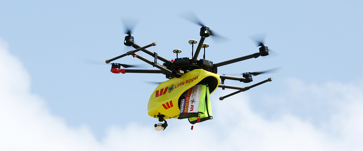
Current drone in place at some major Australian beaches, at some times
Scope of the Project
Design and Produce: - A mid sized drone (5-7"), based off the FPV framework. - The drone is capable of autonomous flight, to a pre-specified location, when directed. - A solution to allow for the aerial drop of a commercially available inflatable floatation system - A solution to allow the drone to be weather-proof and protected when not in flight.
What will NOT be included in this scope, yet could be next : - Live Rescue tests - Autonomous vision to detect people in need of assistance. - Recharging while stored This was list was come to in order to ensure safety, and also make the project achievable in under 3 months
Time Spent - 2 Hours (27/05/25)
Design - Start of the Dock
At beaches, conditions can become unpredictable, thus it is important to ensure that the drone will be able to be stored and protected during all weather conditions, especially where in rural areas in which regular interval maintenance is not feasible. However, this does not mean/make it realistic that this solution would be able to deploy in extreme weather conditions.

Thus, I think it'll be crucial to have a dock/station where the drone is able to rest, ready to deploy when needed.
Requirements: - Weatherproof - Facilitate accurate landing - Cheap! - This drone has the ambition of being deployed in mass, thus price is an important factor.
With this, some possible implementations: - Weatherproof - Closing lid - Storage drawer - Facilitate accurate landing - Feedback to the drone - Use of AprilTags to help drone determine position
What's Already on the Market
Something I firmly believe in is the analysis of existing products and solutions. This can often be overlooked.
Chances be it, most ideas have probably been explored and conceptualised in some form, thus having a good understanding of what has been done allows for an extra layer of innovation, in order to make a meaningful impact on the target market and consumers of the product.
DJI Dock 1

DJI's first generation of drone dock for autonomous deployment.
✅ Advantages - Rugged and durable - Lid swings open to provide a large landing area - Secure - has security and sensors
❌ Disadvantages - Expensive :) - Landing accuracy relies on sensors in drone - Not practical for my application - Requires an external power source to operate
DJI Dock 2

Yeah.. so DJI is kinda popular.
✅ Advantages - Passive entering mechanism relies alot less on drone sensors to get it in - This is really cool - Lid swings open using (by the looks of it) linear actuators, providing a simple, yet robust way of maximising the landing area, while using a very simple pivot mechanism. ❌ Disadvantages - Expensive :) - Landing accuracy relies on the drone - DJI has some pretty cool tech that allows this - Once again not feasible for my purposes. - Requires an external power source to operate
Energy Robotics Drone-in-a-box

AprilTags are pretty cool
✅ Advantages - The April tags allow for very precise landings without requiring complex sensors - Small (this is also a disadvantage) - Sliding drawer improves safety during rain.
❌ Disadvantages - Small. Could get covered over with debris is heavy weather - Landing pad size gives a big constraint. - Seems like a less robust solution compared to DJI
💡 Opportunities and What Worked Well - All solutions require an external power-source - Solar Charging to allow remote deployment - The DJI passive centring is very neat, and a good solution to allow for reduced landing accuracy - AprilTags seem like a good way to help the drone locate itself relative to the station. - I think the fold out design appeal more at the moment, especially considering the terrain of the beach.
Block CAD!!! Another thing which I see as really important is the use of Block CAD to help gain sense of key mechanism parts, and it really helps to plan a design solution.
The goal here is to keep everything as simple as possible.
Initial Concept - Heavily DJI Dock 2 Based
I thought that the DJI Dock 2 provided a very succinct solution to the problem, and the concepts could provide very successful for my project.

The folding doors allow for a clear open space for the drone to take up out of, while then being able to fold in for a compact and succinct solution.
Additionally, the elevation of it allows for the potentially harsh conditions, and prevents it from getting covered and unable to open by sand or debris.

One thing I noticed from the DJI dock was how the indexing funnel was only on one side, and thus looked at implementing it I decided to experiment a bit with adding another flange on the other side. This would mean that there would be quite a large allowable margin for error when designing the landing system. This is a good thing!! It needs to work 100% of the time.

I feel like this concept has the ability to be pretty successful, and tomorrow I will look at trying something completely new involving sliding doors, just to get a sense of options.
I'm however cautious to design too much of the dock before the drone, as priorities will likely shift as the design of the drone (centre piece) evolves. It made sense to lay some groundwork for the dock first though.
A final thought: Manufacturing.. oh yeah, this probably shouldn't be a final thought. Is anything on Day 2 a final thought though.. :) I think it makes sense to try and utilise 3D printing as much as possible for this design, seeing as I'm aiming to keep the costs low for a small-quantity prototype. Industrial manufacturing process such as injection moulding don't make sense at small scale.
Something interesting could be a aluminium frame on the inside to help with rigidity, this could be explored at a later time, once the design is more defined.
Time Spent - 2 Hours (28/05/25)
Day 2 - Further Dock Iterations
The main goal for the dock mechanism is to be able to fold out in order to allow the drone to both take off, and land in a safe and accurate way, while also shielding it from the elements when not in use.
I identified another method of shutting the doors at the top, and rather than pivoting, have them side out of the way, like an opening hangar.

To accomplish this, I first took the base from the previous design, but the first thing I had to alter was the sides.
Seeing as the doors would be sliding out of the way, it would have to be fully enclosed from all sides. To do this, I raised all sides upto the same level.


I came up with something like this, using similar shaped doors as the previous model, but having them slide out of the way. Unfortunately, I don't think this option has much practical validity.

The doors could become quite heavy, which will come with the challenge of.. gravity. As the doors slide further out, the more force will be exerted on the mechanism that is holding it in place, to solve this, more overlap would be needed, yet this will reduce the amount of space the drone has to land in. I don't view this as an acceptable solution to the problem, harming the rigidity of the system.
Overall, I will not be pursing the sliding door archetype further, and will possibly look into some other solutions later down the track. Time to start the drone now!
Time Spent - 2 Hours (30/05/25)
Day 3 - Starting the Drone
I'll be designing a roughly 7" prop size drone, prioritising stability for autonomous flight operations.

I started off with a rough sketch of the dimensions, opting for a stretched X type configuration, to improve the speeds when travelling forward. This will be important when deploying for a rescue.
I currently have 2207 motors already, which have a 16mm mounting pattern, compared to the a more optimal motor for a 7" quad like the 2807, with a 19mm mounting pattern.

The arms will be manufactured from a 6mm carbon fibre sheet. I made the inner part thinner in order to reduce the thickness where not need around the motor mounts. The increased thickness is to prevent bending around the areas under a high load, and long lever. I'll run FEA analysis later to determine if more needs to be done to support this.


I'll also be using a coaxial 2207 setup. This gives a roughly 20% drop in efficiency, yet adds redundance, as if one of the motors breaks or stops during operation, the drone can keep flying. This is important for the high-stakes operating conditions that it'll be operating in. Currently, I have both motors stacked vertically ontop of each other, and am planning on doing a drilling one out to do a bolt through and tap into the other, yet I think this is likey to change.

This is a rough CAD mockup of one side, with the motors and 7" propellers.

In the middle, there is a cutout which will be used to attach the arm mount to the main body.

and.... 7075 Aluminium Billet!! I played around (and still am) which this geometry to get it to be how I desire. This should allow for a rigid, but also strong frame that doesn't break under impacts, while allowing for easy mounting and attachment.
To allow the piece to become lighter, I'll be pocketing it once the geometry is more finalised. I'll likely have it produced at JLCCNC.

A general sketch of the drone layout, with the propellers raised, this allows for the payload to be safe from impacts from the downward facing motor. It was inspired by the DJI Inspire, but also other 8 motor Cinelifter type drones. Let's be honest, it looks pretty cool as well.


Something that I'm going to look into tomorrow is the pocketing of these arms, looking at the weight but also max deformation. I think the shape also needs a bit of work, the propellers seem too elevated at the moment.
Time Spent - 1.5 Hours (31/05/25)
Day 4 - Arm Optimisation
I started off by looking at mounting, and decided on using 4 counterbored M4 bolts per side. This offered a compromise between weight, and rigidity. The counterbore allows it to not get caught on anything.


These bolts will then go into tapped holes in the main body, providing a strong and secure connection

Now, the weight. Using 7075 over something like carbon fibre comes with many advantages in this application, but also disadvantages. One of the main ones is weight. Alot of this material in the middle isn't needed structurally, and can cut the weight in half.
Most of these pockets were just done by sight, from previous experiences I've had.


Each motor gives of roughly 2000g of force (2kg), thus, applying 20N. To calculate the strength of this part, I'm assuming all 4 motors on each side are running at 100% (80N), plus 20N extra. This results in 100N of force being applied directly at the mounting point; however, this is probably unrealistic due to any slight flex in the carbon fibre arms.
Here are some of the test results.
No Skin

1mm skin

2mm skin

For each 1mm of skin, the deflection does down by roughly 0.1mm. I'll see how crucial this is later on in the project.
On a side note.. I'm not too sure of the accuracy of the simulation, but my research indicates anything less than 0.2mm deflection is optimal, so it's looking pretty good considering all of these are done under full load.
Just for fun, heres an example of the part not pocketed. Not too much of a difference which is pretty cool.

Time Spent - 2 Hours (1/06/25)
Day 5 - Bottom Plate
So I did a bit of a silly one... all the FEA was only done with one side of the arm. I'll be getting some quotes from machine shops in the coming days, but this has allowed me to consider whether I really need the full 25mm thickness.

I designed this small block to fit in the middle to allow both of the arms plates to be bolted together. This will currently be made of of 7075 billet as well, in order to ensure rigidity.

I then roughed up 2 plates which will serve as the main body. I don't really like how they look at the moment, and I find the shape to be a bit simple.

The plates were originally attached with 6 countersunk bolts each, but this is going to transition to being 4 to allow for a small bit of weight saving, while not compromising on rigidity.

I also added the RPI Zero 2 W, this will handle on-board april-tag recognition to allow for precise landing. This footprint is quite large on the drone.

The stack is mounted at the back of the drone, where the battery will sit ontop of. I have to use 2 of the 4-in-1 ESCs from Speedybee to accomodate the 8 motor setup.

I also designed a riser to allow for the ESP32 telemetry module to sit on. I'll be designing the PCB for this shortly. I'm not too happy with the layout at the moment. and I think I could 100% make it more efficient.
Tomorrow I'll be adding in the AprilTag camera, and maybe starting on the FPV camera as well. I had one idea to make that pivoting, but I'll see if it can be integrated into the budget, as currently it is looking very tight with the large expense of the CNC arms.
Time Spent - 3 Hours (2/06/25)
Day 6 - Further Refinements

As I mentioned yesterday, I wasn't too pleased with the overall shape. To improve the aesthetics I added a small taper at each end, which seemed to do it for me. I think just the overall boxy shape was what was weighing it down.

I mounted the AprilTag camera, I'll be using the OV9281-160. It's a monochrome camera, which will allow for faster processing on the Zero 2 W, and allow for a more responsive algorithm.

I also designed a mount for the FPV camera that the front that will be sending live video back to the operator.

I wanted it to be able to fit the VTX on the back due to size constraints, and this worked out pretty well. This will end up being 3D printed from TPU, or CF-Nylon.


I originally went with a smaller camera (10AUD), but ultimately realised this looked a bit out of proportion for my use and just looked a bit weird at the front. I also didn't like the fact that the PCB was exposed. I ultimatley went with a slightly more expensive option, but allowed for a much nicer solution. I felt like spending money here would be justified, and I'd prefer not having to order the more expensive option once I worked out the smaller one didn't work.


I also did this case at the back that holds M4 standoffs, for the carbon fibre plate, while also protecting all the electronics inside. I added a 3mm recess in the middle to allow for the ease of routing around the ESC, and I think this actually looks really good! This will probably be printed from CF-Nylon, and will add a nice stylistic touch on the side.
It feels like it's definelty coming together now!
In other news, I've been contacting a few factories looking for machining services for the arm parts. These are very complex, and thus I'll need to outsource them. The company is doing this for a very reasonable price, with a low order quantity. These are made from 1" 7075 billet, which will definitely help with rigidity inside the drone. I would like to order 1 spare, unforchantly I don't believe I have space in the budget for this.
I'll be looking soon to finalise the part with wiring considered, then get it off to them for a final quotation.

I've also been in contact with a few for the carbon fibre as well, and there is one that looks very promising! Hopefully more on that tomorrow.
Time Spent 3 Hours (4/06/25)
Day 7

I started today off by integrating an XT60 connector on the back. This will allow the battery to plug in, in a rigid way. I preferred this over having a loose pigtail due to it's reliability, with no additional cost. This also allows the inside to be completely protected. Yet, a problem I identified with this is potential build up of heat inside. I'll look into how to fix this soon.


The camera has space inside for a small bit of pivot to allow for adjustments based on how I want it to look when flying. I don't really like aesthetically how it looks from the front.. but it's whatever. That can/will be changed later.

Wow! It look pretty good at this point. Here's a list of what I have left to go:
- Battery Mounting
- Drop Mechanism
- Antenna/GPS mounts.

and.. I found a problem. I only ever planned to have the carbon fibre arms supported from the top... whoops. I added a small recess to the bottom to allow it to be clamped down.

My budget is looking pretty sad right now. Unfortunately I'm 180USD over. I already have some parts to construct this, but apparently it wasn't enough. I'll have to look how to cut a few cots, then I'm probably going to have to support it myself the rest of the way. My suppliers have all given very competitive prices, so I'll just have to see how things go and cut where possible.
Time Spent 3 Hours (5/06/25)
Day 8 - Battery
I started today off by doing alot of reaserch on different battery options available to me locally, and eventually settled on this one.

I thought this offered a pretty good life-span, while delivering adequate power to the 8 motors. Unfortunately, it is a little bit pricy.. at 110AUD (70USD)

I designed this plate that would go on top to allow for the strap to rest underneath it, which is a pretty simple and succinct solution.
Tomorrow I'm going to look into doing the PCB for the telemetry, and then doing the antenna mount for that. The FlySky transmitter that I already have has an antenna built in, so I'll just need 2 mounts. 1 for the VTX and one for the Telemetry.
Just a short one for today.
Time Spent 1 Hour (8/06/25)
Day 9 - Telemetry Board
The cost has been worrying me for a while, so I decided to review the scope. I have ultimately chosen to not pursue the Pi with Camera for landing at the moment. This will come later in development, once the drone is proven to work, and I'll assess the need with how well the GPS works. This helps shave 80AUD (52USD) off the cost, which is helpful.
With that, I started work on the PCB for the telemetry. This will be pretty simple, using mounting holes and then solder pads breaking out the ESP32-C3. For the firmware, I'll be using the drone bridge firmware.


The PCB ended up being rather simple, with was unfortunate, but it'll do the job, and be functional for my needs.
Time Spent 2 Hours (10/06/25)
Day 10 - Finishing Touches

I added a hole for the USB-C port to allow access to the flight controller in the middle onto the side of the protective cover.

I also added a top facing GPS mount at the back. It is angled 10 degrees upward to assist with connection during inherently angled flight.

A hole then feeds into the back of the drone, allowing it to be connected to the main flight controller.

I also selected a servo and started cadding it. The main issue was finding one with a good enough drawing. Ultimatley, I did for a reasonable price, and also power. It'll fit perfectly (30mm in 30mm) inside the drone (once 2mm is filed off.. anyways). Tomorrow I'll integrate this into the billet block in the middle.
Time Spent 2 Hours (12/06/25)
Day 11 - Drop Mechanism

The manufactured ended up finding a step file of their product, and sent it to me overnight. This was really helpful in getting an accurate snapshot of the model.

The space which I have inside the middle block is... small at best. I think I struggled for like an hour on Aliexpress and Alibaba trying to find a compatible servo horn.. I was not successful. I'm going to just 3D print it and hope for the best, but it did help me build in the first of 3 stages for the linkage.

This one will hold a steel dowel pin, which will end up supporting the load.

This was Version 1 of the intermidate stage, which was later changed
Ultimatley, they all come together to be able to provide parallel and linear motion from the rotation of the servo.

The shaft will then be supported on 2 faces, such that it is always in contact with 1 bushing. This, as well as the vector 'funnel' in will be designed tomorrow.

Looks pretty nice. The packaging ended up working pretty well. I'm very pleased with how everything is going, and I want to be submitting by the end of the weekend so I can start ordering all the custom parts.
Time Spent 4 Hours (13/06/25)
Day 12 - Wiring Diagram
I have attached an image in the repo. This isn't final yet, but is unlikley to change. I designed it in Adobe Illustrator.
Time Spent 1 Hour (14/06/25)
Day 12.5 - Almost ready to ship.

As planned, I added a second bushing to serve as the linkage. In CAD this seems to work pretty well, but I suspect it will need some tweaks when all the parts arrive.

This is it in it's fully extended, compared to fully retracted states.

I also added 8 WS2812 LEDs on the front, to both serve as a flash for the camera, but to also provide a sense of direction to the drone. I think it kinda looks cools and changes the shape up a bit, adding visual interest.
I also changed the front plate shape to mirror this.


I also added 32 LEDs on the arm (16 each side) to provide enhanced visibility, enhancing safety.


and that's the end product!! I think it looks pretty amazing.
As mentioned earlier (I think) I'll be using Ardupilot to program it, and thus can't do any work on the firmware until all the parts arrive.
Time to Ship!
Time Spent 5 Hours (14/06/25)
Day 13 - Ordering
With much success, I've pretty much ordered all my parts!
Slight problems were discovered. This motors which I originally planned on using were not sutiable, luckily, I was able to find 8 new ones on Taobao for a pretty similar price. I'll now be using 2810 1300KV motors.
Time Spent 2 Hours (19-21/06/25)
Day 14 - The Start of Part 2
I've split this project into 2 parts, the drone and dock, each bringing their own special challenges.
Bridging from the block CAD at the start, I added some more detail to the pivoting doors.

The chamfer adds some visual depth, while then the holes at the bottom allow for the 25mm tube to fit through, which is then secured using compression.

This 25mm rod will then be supported by an array of bearings.

Time Spent 3 Hours (2/07/25)
Day 15
Today was fun, all the Aliexpress components have arrived! Everything looks in order. I'm just waiting on the factories producing custom parts to ship now, and it looks like assembly should start mid next week!!
Today, for the dock, I added in the linear actuators, which will provide the opening motion.
The linear actuators which I'll be purchasing have inbuilt stops, meaning it is possible to just apply 12V in 2 directions in order to achieve the full range of motion. This will end up heavily simplifying control.

This is it fully open.

This is it in the stowed state.

There is then a cutout in the main base to house the actuator.

In terms of control, it'll be powered off a 12V lead-acid battery. Then a custom control board will be made based off a SeedStudio Xiao (or similar based on how many pins I need) to interface with both this button panel, and a stack light to provide visual and auditory feedback.
The button panel will allow for manual operation during the prototype phase.

The stack light (which will be similar to the one below) also contains a buzzer, useful to help prevent accidents.

Time Spent 4 Hours (3/07/25)
Day 16
Today I was going to start with designing the PCB, though, I pretty quickly found the exact thing that I needed on Aliexpress. This will end up saving me time, allowing me to focus on other areas of development, and delivery heavy cost cuts.
This will also negate the use of a microcontroller, increasing reliability. Unfortunately, this also means I will not be pursing the stack light avenue.

With this, I added colour to the model. The white will be printed from PETG (I purchase this locally for 10USD per kg), and then the black landing pad from TPU, for extra wear resistance as the drone comes 'crashing' down into it (once again, 10USD per kg).


I also added the control buttons on, this will also serve as a door which can be opened to access the electronics inside.

Internally, there is also spacing of which the wires will run through.

With this, the design of the dock is done.
I finalised the readme, and have now submitted this second part of the project! Apologies if any of the images struggle to load.
Time Spent 6 Hours (4/07/25)
Drone Parts Update!
All components have arrived! The carbon fibre looks incredible. Yet, I'm currently messaging the CNC supplier, as they are having a slight problem with following their original timeline to ship the product.
It's just anodising left, and hopefully it'll ship this week. Looking forward to starting to build this!!