Haptic Joystick System
Total time spent (On design): 74 hours
Ruzanna: 42 hours
Philip: 32 hours
June 6, 2025 - 2 hours
What we did:
Today we brainstormed ideas for a project that would allow us to incorporate a two-way haptic feedback system and potentially wirelessly interact with robotic builds that have a functional haptic feedback system.
We decided to build a wireless haptic controller that can interact with a robotic arm through pressure-based feedback and multi-axis (XYR) motion input. We will use this controller to control out previous highway project, which is remote haptic feedback hand (check out at https://github.com/xsollwa/remote-assist-hand)
The controller works by letting you control a robot or device using your hand. When you squeeze the air bulb, it sends air to a pressure sensor, which tells the microcontroller how hard you’re squeezing. That information is sent wirelessly to either a robot hand or a balloon that gets bigger or smaller depending on your squeeze. The joystick lets you move the robot left, right, forward, and back, and the knob lets you rotate it.
We also will use a small air pump connected to the bulb to let you feel what the robot is feeling. E.g., if the robot grips something hard, the system pushes air back into your bulb, making it harder to squeeze. This creates two-way feedback because you're not just sending commands buy feeling what’s happening on the other end.
June 7, 2025 - 2 hours
What we did:
Ruzanna
Today I created the GitHub repository for this project with its necessary files, and submitted a pull request to Highway project gallery.
Philip and I had a discussion about all materials we would need for this control pad. After having a good idea of how the controller will function I attempted to create the first detailed design sketch of it. This initial sketch would serve as a visual aid to help us conceptualize how the various components will fit and interact within the final assembly. Here is the first sketch with the labeled components!
After showing the sketch to Philip, we figured that although this control pad would be functional, it would be quite uncomfortable to use. Instead of this design, we decided to incorporate a design that would be fitted to the hand (like an Xbox controller), where the index finger and the thumb of the right hand would pinch the small air bulb, and the left hand would be used for XYR controls. (Also I was missing an air pump in my sketch, which needs to be used in the two-way feedback system)
June 10, 2025 - 3 hours
What we did:
Ruzanna
Following the aforementioned feedback I proceeded to create the 3d design of the controller using OnShape. The holes for the electronics are made considering the sizes of the parts that we found online and planned to obtain. Here are some screenshots: (This is my second ever 3d design!)
I sent the 3d design over to Philip for review, revisions and fixing if needed.
June 11, 2025 - 4 hours
What we did:
Ruzanna
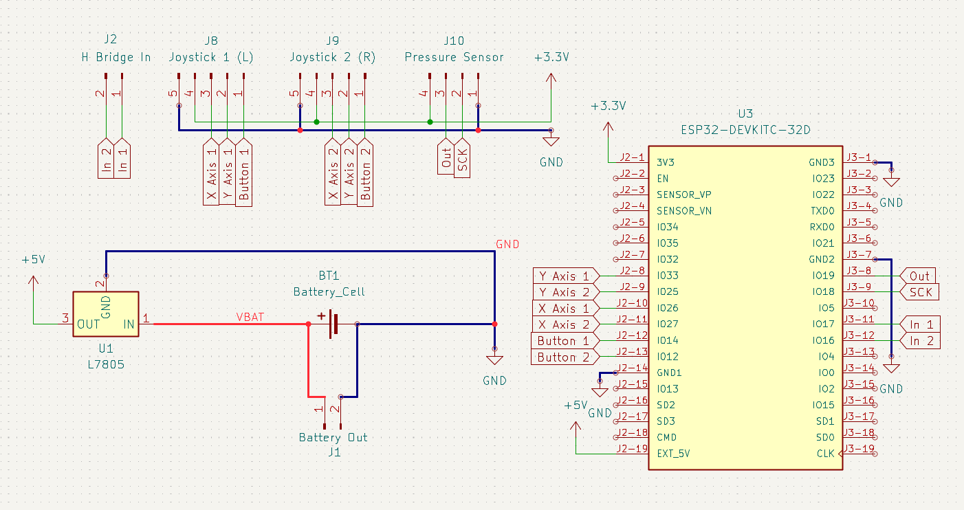
- Today I created the first schematic for the controller pcb. It was my second time using KiCad after solder so it took A WHILE... but I finally got all the connections in place. I used an ESP32 module as the main microcontroller and wired up a joystick, pressure sensor, potentiometer, and MOSFET-controlled air pump. Getting the voltage regulator set up correctly for the ESP32 was a bit confusing, and figuring out how to wire the MOSFET without frying anything took a few tries. I also added a flyback diode for the air pump to prevent voltage spikes. Laying out all the component symbols and making sure each one had the right number of pins connected was tricky, especially with the ESP32. But by the end, I had a complete schematic I felt pretty good about. Here is a picture of it:
- I sent the schematic to Philip for a double check and some feedback, and it turned out that I was using the wrong ESP32 model and batteries the whole time (I had selected the ESP32-WROOM-32 instead of the correct ESP-WROOM-32, and I was designing around a 4.7V battery instead of the required 7.4V). Philip also also recommended replacing the step-up converter with a buck converter to provide a more stable 5V output for both the microcontroller and the sensor. After reviewing these suggestions, I went back and revised the design. Following the corrections, I created the second (and correct!) version of the schematic:
June 12, 2025 - 2 hours
What we did:
Ruzanna
- Today I completed the final PCB layout for the controller. One of the biggest challenges I faced was routing all the connections — with so many components in a compact space, it quickly became difficult to find clean paths for every signal. Eventually, I learnt about vias and used them to complete the pcb!
//nothing super interesting on the back of it
- We also familiarised ourselves with the process of ordering pcbs through PCBWay, since it would be our first time using it.
June 13, 2025 - 2 hours
What we did:
- Today we got the chance to share both of our projects at the Highway Show & Tell with strange parts! It was really interesting and exciting to see all the unique projects made by other hack clubbers, and we certainly learnt a lot from the feedback given by Strange Parts.
Ruzanna
- I created the Bill of Materials today, and found all of the parts that we would need to purchace for this project. Everything is written out, including where we will be obtaining the part from in the MATERIALS-AND-BUDGET.md
June 15, 2025 - 1 hour
What we did
Ruzanna
- Today I completed the README.md file of this project. In the README I covered the overview of the project, its key features, components, work process, build process and included links to important files such as the MATERIALS-AND-BUDGET.md and JOURNAL.md.
June 17, 2025 - 2 hours
What we did
Ruzanna
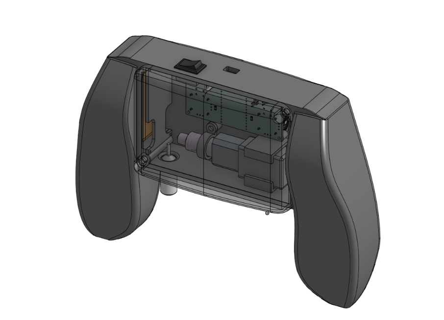
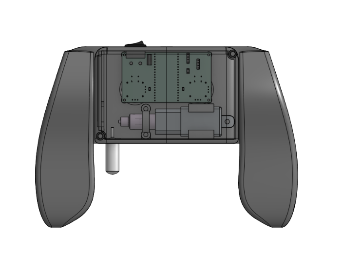
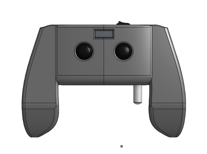
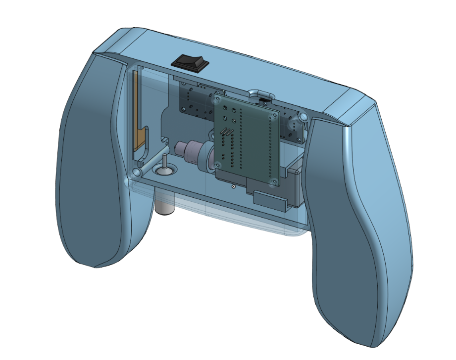
- I uploaded and/or cadded all of the necessary components into my OnShape assembly and put (almost) everything together!
June 20, 2025 - 3 hours
What we did
Ruzanna
- After checking out other joystick designs, I realized my first version would likely be uncomfortable to hold and wouldn’t have enough room for all the components. Because of that, I decided to redesign it from scratch. My updated version has more internal space and an ergonomic shape that better fits the natural contours of the hand, making it much more comfortable to use. So far, I’ve made good progress on version 2 in CAD. It took some time to learn how to use the loft feature properly though.
June 22, 2025 - 4 hours
What we did
Ruzanna
- I decided to fully redo the controller design again because I wasn’t happy with how it turned out. I thought I could make a cleaner and more comfortable version from scratch. I rounded the overall shape a bit and changed up the handles so they feel better in the hands. I also tried out different layout ideas for the joystick modules and the air bulb to see what would work best. Sketching these out helped me plan the controls and think about how to make everything easier to reach and use. Here are some of my sketches and my third version of the controller!:
- We also decided to get rid of the potentiometer and use two dual axis joystick modules to be able to percisely control all the motors on the arm.
June 25, 2025 - 2 hours
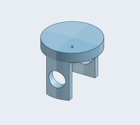
- Today I designed the holders for joystick modules and the battery.
June 28, 2025 - 3 hours
What we did
Ruzanna
- Today I mostly focused on designing the controller lid in CAD. I worked on modeling the mounting holes so they would line up with the rest of the assembly, and I also created the cutout for the USB-C port. While working on the lid, I re-mapped the arrangement of all the components inside the cover, since there’s not a lot of space to work with. I tried to place things as efficiently as possible to avoid any interference and to make sure the wiring would stilll be manageable.
- Later on, we realized that our air pump is not reversible, which would be a problem for creating a functional two-way haptic feedback system. Since we wouldn’t be able to both inflate and deflate the bulb with a non-reversible pump, we started searching for a new reversible air pump. Unfortunately, none of the reversible pumps we found were small enough to fit inside the controller’s limited capacity.
As an alternative, I suggested using a standard air pump along with a valve system. The idea was to switch the pump’s input and output toward the bulb depending on whether we wanted to inflate or deflate it. That’s basically how most balloon inflators and deflators work. But, Philip pointed out that this approach wouldn’t be precise enough for our project, where we need fine control.
Instead, Philip came up with a better mechanism using a syringe moving by a servo motor to move air in and out of the bulb. This design would be a lot more precise while still staying small enough to fit in our controller. After talking it through, we agreed that this was the best way to move forward. Here’s the sketch that Philip made to show the concept:
- We also figured that our current MXP5010DP sensor does not tolerate pressure above 10kPa, so we decided to switch to Barometric Pressure Sensor Module which can handle up to 40kPa
June 28, 2025 - 3 hours
What we did
Philip
- I assisted Ruzanna in brainstorming and creating sketches for possible designs of the controller, specifically considering the use of a motor to push a syringe and precisely control the air pressure within the bulb, as explained above.
June 29, 2025 - 3 hours
What we did
Ruzanna
After coming up with a better mechanism for the controller, which uses a bulb, a syringe, and a servo motor to move the syringe plunger, we started searching for new parts. We found a 4 mL bulb that would fit nicely into the controller, and I ran some calculations to figure out how much air we’d need to inject to reach our maximum target pressure of 50 kPa (about the same as a firm pinch).
Since the normal air pressure is around 101 kPa (atmospheric), raising the bulb’s pressure to 151 kPa means you’d need to increase the amount of air inside by roughly 50%, so about 50% more air molecules. That comes from the ideal gas law, since pressure and the amount of air are directly proportional in a fixed volume. The bulb’s volume is 4 mL, so at atmospheric pressure it already holds 4 mL worth of air. To get to 151 kPa, you’d inject about 2 mL of air at atmospheric pressure, because the ratio Pressure 2/Pressure 1 equals the ratio of the final to initial air quantity. So we knew we would need a syringe that could move at least 2 mL of air.
Our previous 2 mL bulb wouldn’t have handled that kind of pressure swing without deforming too much, so switching to a 4 mL bulb was the safer option.
- Next, we went looking for a 2–3 mL syringe small enough to fit inside the controller. Unfortunately, there weren’t any standard syringes in that size range that would physically fit into the space. So we took a 10 mL syringe and decided to cut it down so it could still handle the air volume we needed but stay small enough for the design.
- Next, we had to figure out how to move the syringe plunger. At first, we planned to use a servo motor, but later Philip found a linear actuator that would be a better alternative because of its uniform horizontal movement and its relatively small size. That should give us more precise control over the air pressure and more consistent haptic feedback.
June 29, 2025 - 2 hours
What we did
Philip - As Ruzanna has detailed above, I assisted in brainstorming and discussing the design of the controller, finding new parts and ideas for how the two-way haptic feedback system will work.
June 30, 2025 - 2 hours
Ruzanna
- Today I imported or designed the parts (new 4ml bulb, new switch, lipo) that we will be using moving forward, and updated the Bill of Materials with the new parts that we found.
July 2, 2025 - 4 hours
What we did
Ruzanna - Today I mainly worked on CAD-ing out the parts (syringe and actuator), casing for electronics and updating the Bill of Materials with the new parts!
Battery casing:
Syringe (and its holder) and actuator:
July 2, 2025 - 7 hours
What we did
Philip
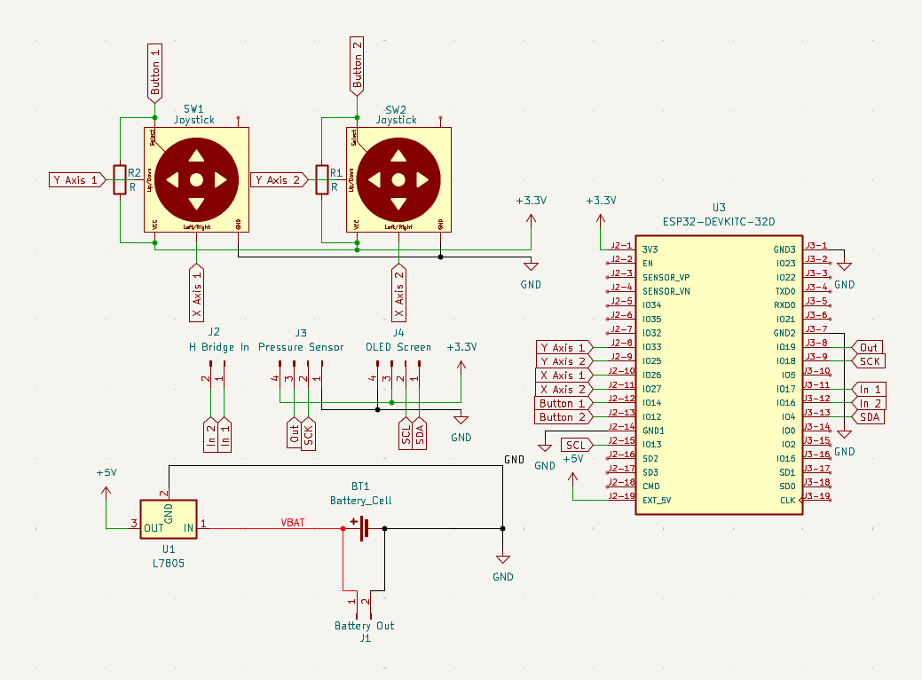
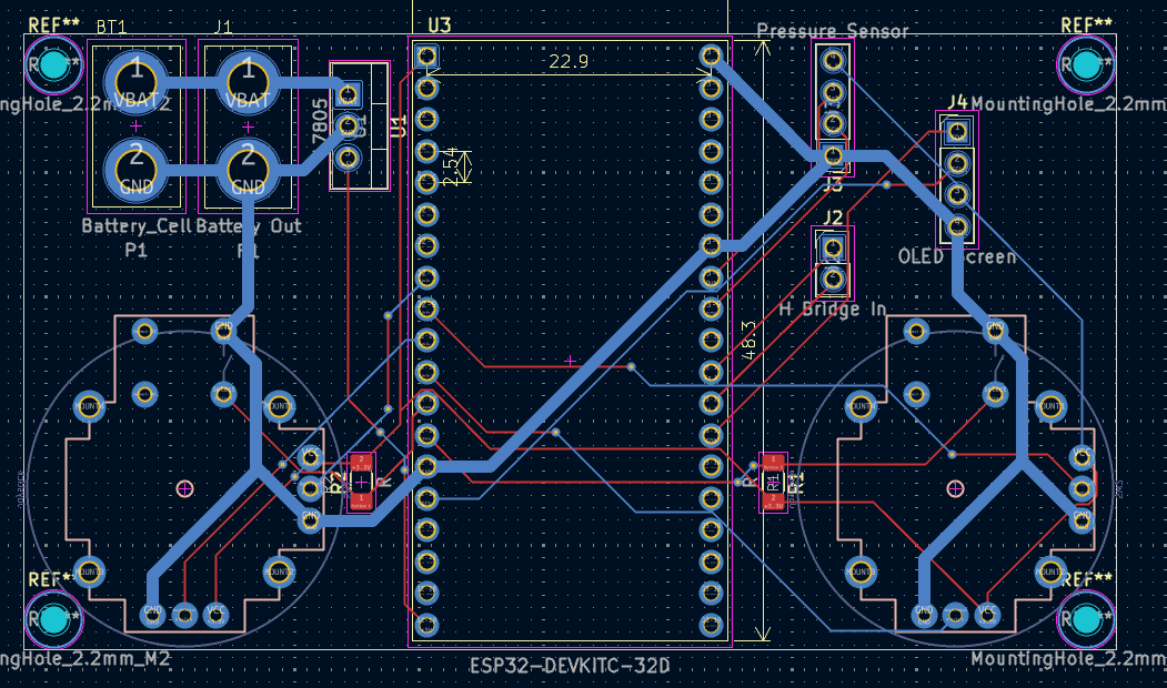
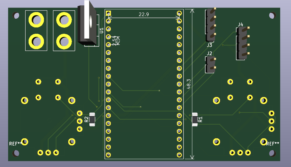
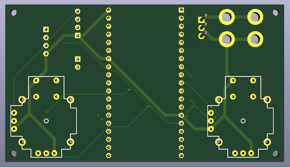
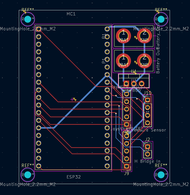
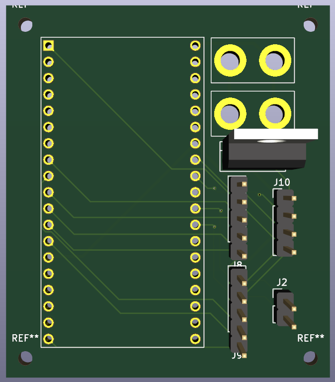
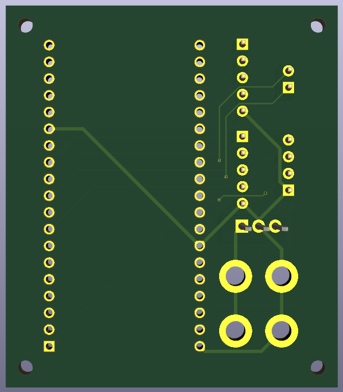
- Today, I worked on remaking the PCB that Ruzanna had previously worked on, since the planes for the controller had changed a lot recently. Many of the parts we had to include also changed. I also had to update some of the footprints she was using since I had mistakenly given her the wrong ones. Using her previous PCB design as a reference, I remade it, making it more compact and changing the components to suit our needs. Below are images of the new PCB.
July 3, 2025 - 6 hours
What we did
Philip - Today, I created the code for the ESP32 controller and modified the code from our ARM project so that it can be controlled not only through the webpage but also through the controller, allowing for a proper two-way closed haptic feedback system. This system will work by the ESP32 in the arm sending amplified signals from the load cell in the grasper, giving pressure feedback. In the controller there will be a 4mL pipet bulb which the user will squeeze which is hooked up to both a pressure sensor as well as a syrige filled with air and a linear actuator which will increase the pressure in the bulb to a maximum of 40 kPa (the equivalent of a tight pinch) as the load cell expereinces more and more force. However, as the pressure rises from the user squeezing the bulb, so will the force on the load cell as the grasper squeezes tighter.
July 4, 2025 - 5 hours
What we did
Philip
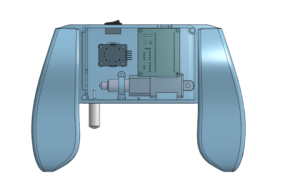
- Today, I worked on refining the CAD and preparing it for printing, adding the plunger adapter part for the linear actuator, and making adjustments to tolerances. I also ensured that all threaded inserts and screws would fit well into the design. Below are some images of the adapter and the completed CAD.
July 6, 2025 - 3 hours
What we did
Ruzanna - Today I organized the repository, made the final changes in readme, BOM, the journal and other files, making sure everything meets the submission requirements.
July 10, 2025 - 1 hour
What we did
Ruzanna - I made some changes in the code to improve how the joystick data is handled. I made the joystick center values calibrate automatically instead of using a fixed number. This helps the robot move more based on the real joystick position. I also added Wi-Fi and WebSocket reconnect logic so the it can recover if the connection drops.
July 18, 2025 - 2 hours
What we did
Ruzanna - To make this controller more advanced, Philip and I decided to utilize all of the buttons on our joystick modules and add a little display. It’s one of those tiny 128x32 displays, and I got it coded with the Adafruit library. I set it up to show four different screens that I will be able to flip through by clicking down on the joystick buttons.
The pages show: - Arm force (from the robot’s grasper) - My bulb pressure (from the HX711) - Live joystick values (to check how it’s reading my input) - And a little status screen with Wi-Fi info and whether the WebSocket is connected
July 19, 2025 - 5 hours
What we did
Philip - Today, I focused all my efforts on putting the finishing touches on the project while striving to make it advanced. Specifically, I worked primarily on the PCB, integrating the joystick modules into our custom PCB and adding connectors for the OLED screen. Additionally, I ensured the PCB was well-equipped to handle the high power from the LIPO battery by utilizing KiCAD's netclasses and making certain vital power connections thicker to support the high voltage and current. Additionally, I refined the CAD design, modifying the mounting position for the PCB to accommodate the embedded joystick modules, as well as relocating the programming port. Overall the design for the controller is quite advanted with the two way closed pressure feedback system which requires precision controlls and calibration, its power scheme from a lipo batter being used not only to power the microcontroller, sensor, joysticks, and screen through a 5v regulator but also powering the linear actuator directly, lastly with this precision custom PCB I am very proud of this project. Below are pictures of the updates I have made.