
Remote Assist Hand
Total time spent (On design): 108 hours
Ruzanna: 30 hours
Philip: 78 hours
May 27, 2025 - 2 hours
What we did:
- For our first work day on this project, we focused on brainstorming and research to get a clear picture of what we want to create. We discussed different project ideas that we had, some of which were focused on medical devices because of interest in biomedical engineering. After going through the pros, cons, and what the build process would look like for each concept, we decided to make a robotic hand with haptic feedback. The idea is that the hand could be useful in situations like small-scale surgeries or remote object handling where you need a sense of touch
or grip resistance.
One challenge we had was figuring out how to successfully achieve a functional haptic feedback system. After doing some research, we decided on trying to implement haptic feedback based on air pressure. The concept seems simple and effective. we’ll use a small tube with that you squeeze with your hand. The more you squeeze it, the more pressure it senses, and the robotic hand will close proportionally to that pressure. We want it tp work both ways. When the robotic hand feels resistance (like from gripping an object), it pushes air back into the tube, which increases the pressure and makes it physically harder to squeeze.
To make the use of the arm easier, we decided to make it remotely controllable, and we are planning to use a joystick or remote control for that (We will make a joystick/controll-pad for robotic hands with XYR controls, airbulb and haptic feedback system for our second Highway project!). Here is one useful article that we read to get an insight on how to build remotely controllable robot arms: https://www.instructables.com/remote-controlled-robotic-arm/
Here is a useful video that we watched which was also about building robotic arms: https://youtu.be/5toNqaGsGYs?si=Z9oADLPzUGIuOL0S (The robotic arm in this video is pretty big but ours will be smaller)
June 3, 2025 - 4 hours
What we did: - We set up Visual Studio Code Git extension and cloned the project repository to our computers. We did this to make the workflow smoother since we plan to write the C code for our Arduinos in Visual Studio Code.
- We chose the mechanical parts such as the stepper and servo motors to drive the arm based on power requirements. We also chose our microcontroller allowing for Wi-Fi connectivity using an Arduino model for familiarity. Added these components to the Material and Budget file listing their prices and linking to possible vendors.
June 4, 2025 - 1 hours
What we did: - We met to brainstorm and discuss the physical design of the robotic arm, more specifically the size of the robot, and how the CAD and PCB would look like. We came up with a design that would be slightly smaller than real human arm because of the strength and size of the motors we are planning to use.
- We began sketching out the CAD design on paper, dimensioning out the arms and making sure our servos can support the torque provided by the weight of the arm. This should allow for easier CADing in the future and smooth operation of the arm.
June 5, 2025 - 2 hours
What we did: - We continued to add to the Materials and Budget list allowing us to shape out the details of the claw itself as we found components needed for the pressure feedback such as a load cell and amplifier. Now having the components needed for the arm we plan on moving onto finding the components for the controller and fully CADing out the arm.
- We also had the meeting with Alex to discuss our project and progress. He suggested using an ESP32 microcontroller instead of the Arduino Nano, as it may be more cost-effective and have better WiFi capabilities, so that is what we will move forward with.
June 6, 2025 - 2 hours
What we did
Ruzanna
- Today I created the first detailed drawing of our robotic arm design. The goal was to visualise how each component would physically fit together; it includes labeling of all of the parts that will go into building the arm (servo motors M1-M4, stepper motor Mst, gripper, load cell L1, amplifier A1, ESP32, MPX5010DP with its tube, and LiPo battery). Here is the first sketch!
- After sharing the design with Philip we discussed how feasible it is and how the pressure feedback system should work. Originally I drew in MPX5010DP with a tube to register pressure, but we ended up coming up with a better way. We agreed to measure haptic feedback electrically through a load cell L1 which measures the amount of bending force applied by the gripper. So, I revised my drawing to its second version by removing the air pressure tube with the MPX5010DP sensor , and included a pressure display on the arm to show live force readings using the load cell. Here is the revised version of the sketch:
June 11, 2025 - 4 hours
What we did
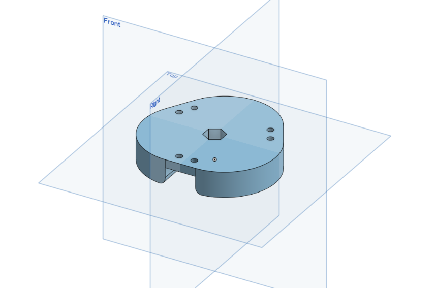
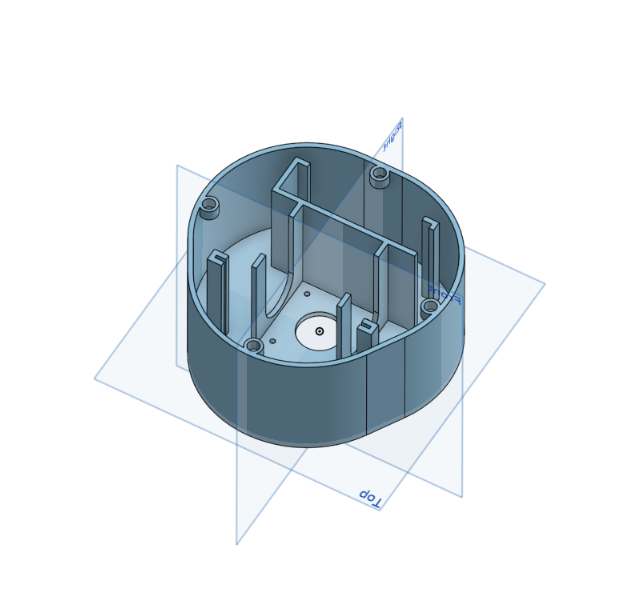
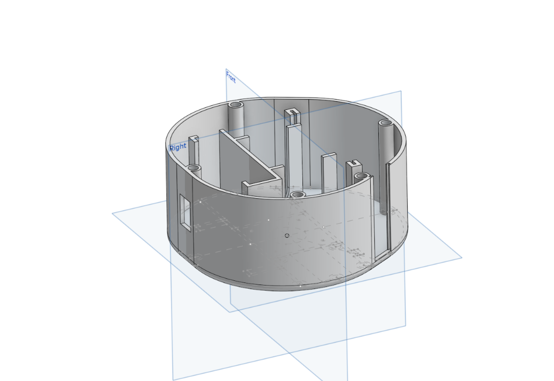
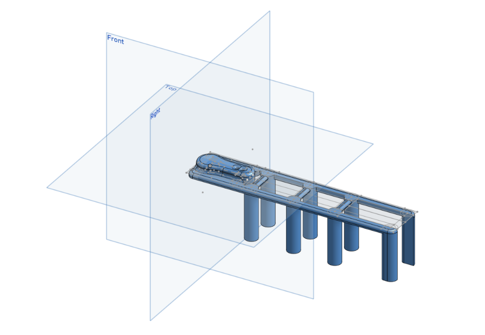
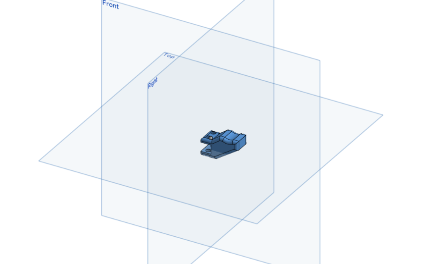
Philip - Today, I worked on fleshing out many of the ideas Ruzanna and I had previously discussed by CADing out some of the significant parts of the arm. I started by importing models of the stepper and servo motors we would be using, then CADing out the load cell as well as the Hex adapter, which would allow for 360-degree rotation. Next, I designed the stationary base, as well as the component for storing various electronics, including the PCB and stepper motor. These parts are denoted by the color blue, as we will 3D print them to construct the arm.
Tomorrow, I plan to create the PCB design for the arm, which will enable me to scale the arm more effectively and continue refining the current parts that I will be printing. I am attaching images of my CAD progress thus far.
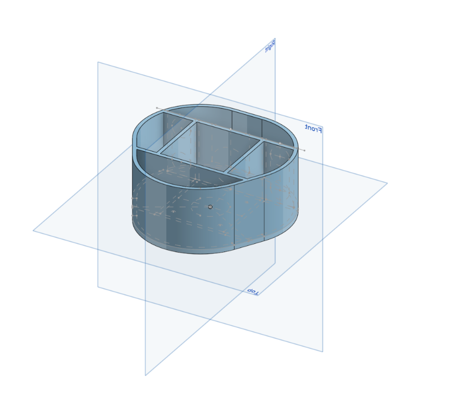
The top image shows the stationary base, while the bottom represents the electronics casing, which will sit on top of it, supported by the hex adapter and stepper motor shaft.
I also conitnued to form on the BOM and will be adding these updates tomorrow as I finish CADing.
June 12, 2025 - 7 hours
What we did
Philip
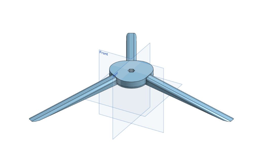
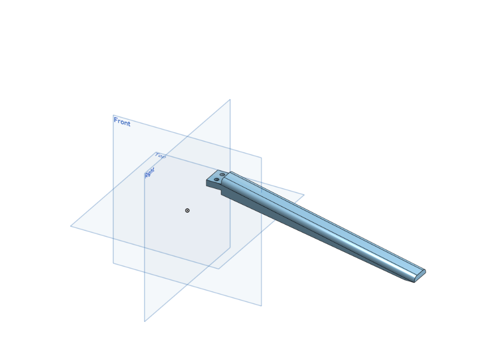
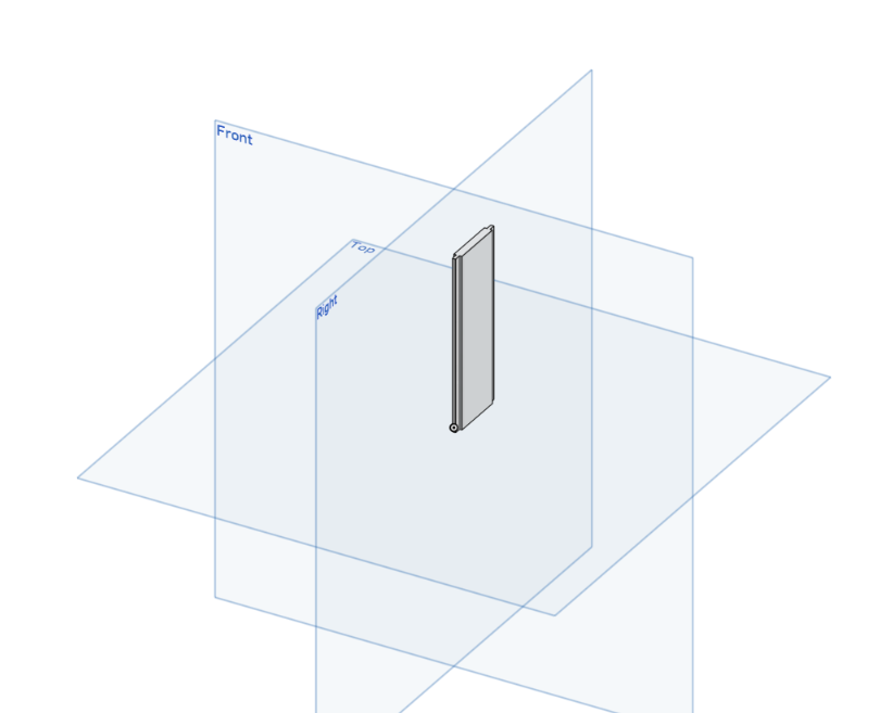
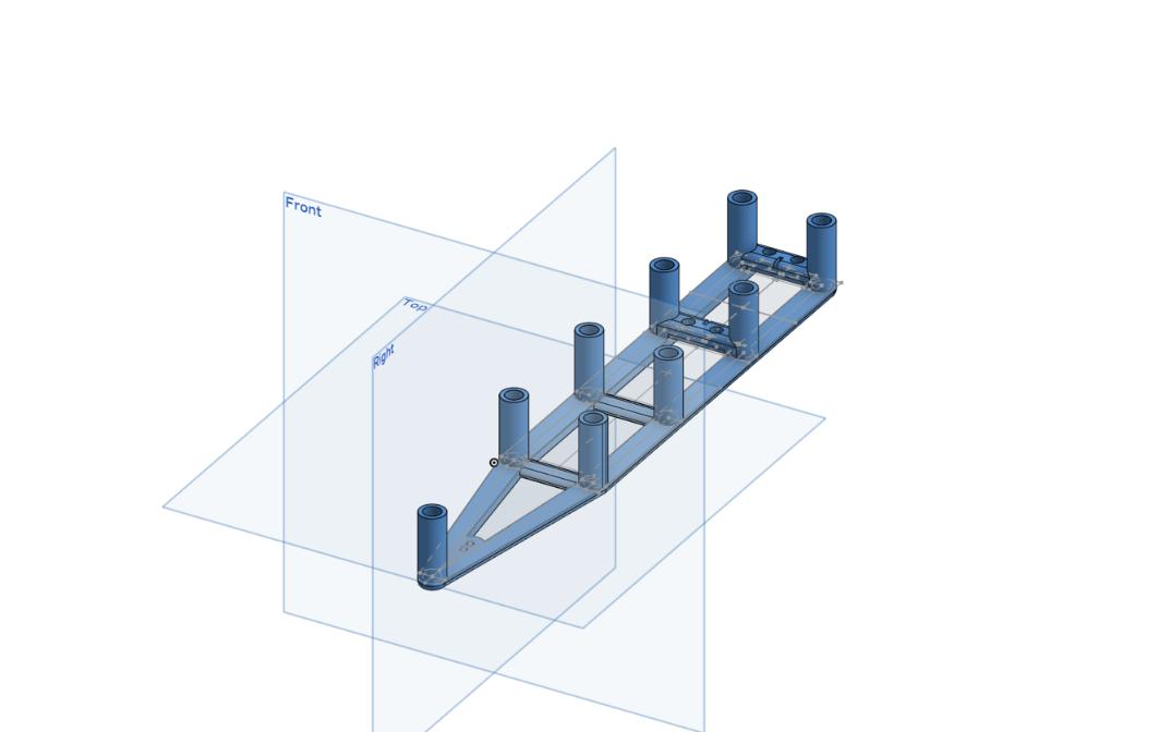
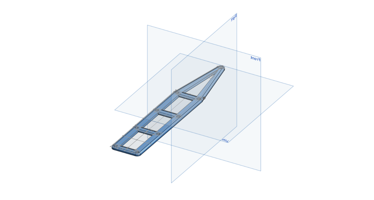
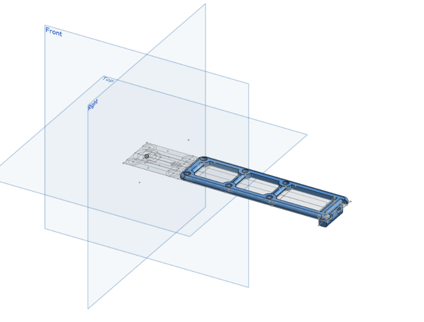
- Today, I continued working on the CAD, mainly changing the base so that the legs can be printed separately from the base center. This change was to allow for the printing of these parts, as the combined model would not have fit on my 3D printer otherwise. Additionally, this will enable me to scale them to larger sizes if needed. Below is a picture of the new parts.
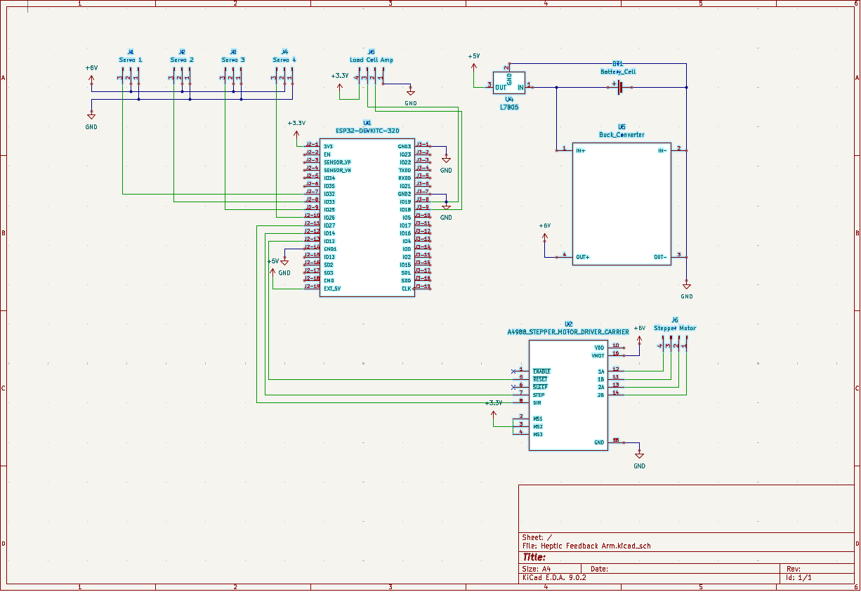
- The bulk of my work today was spent on KiCAD. Today was my first time using the software. Thus, I spent a considerable amount of time learning how to use it. However, I was able to create my wiring diagram and start my actual PCB design. Below is a picture of my complete wiring diagram.
June 13, 2025 - 5 hours
What we did
Philip
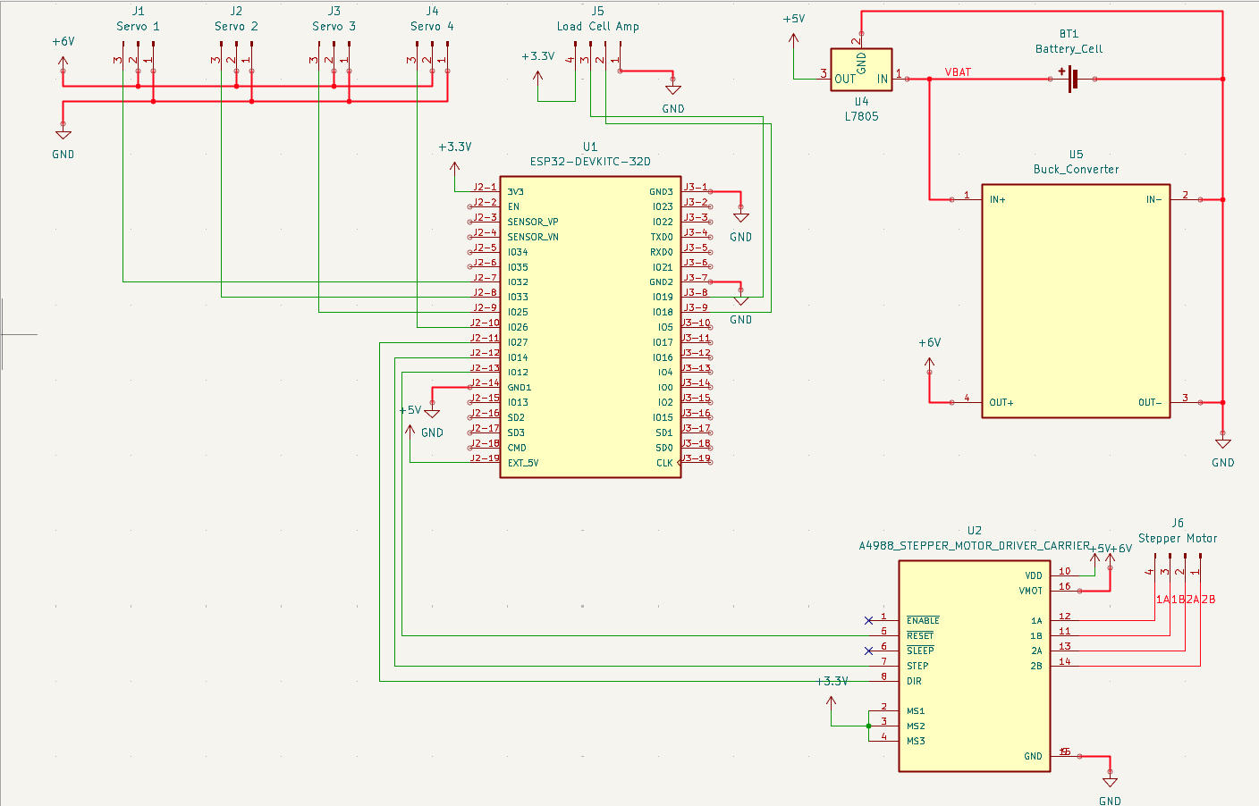
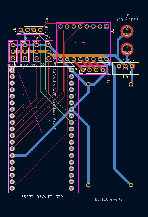
- I continued to refine my wiring diagram in KiCAD. I was able to complete both tasks, fully optimizing the PCB design for the smallest size while ensuring all the proper electrical connections were made. A part of this design process that took me a while to figure out was creating different nets, which I used to make the connections between my battery and other high-power connections thicker and make those connections as short as possible to reduce voltage drop. Below are pictures of both my complete wiring diagram and PCB design.
- Next, I imported the 3D model of my PCB into OnShape. I refined my Electrical Casing Design, as well as the base, to allow for the proper amount of space to fit all the electrical components. This resizing included the base center to accommodate the new, enlarged size. Below is an image of the new casing.
June 14, 2025 - 5 hours
What we did
Philip
- I continued working on the Electronics Case, notably adding a panel to access the ESP32 while the lid was screwed on, allowing for easy programming. Additionally, I added a hole for a switch that will enable me to turn off the power from outside the case, even when the lid is screwed on, which protects my programming device from high voltage. Next, I added the lid to hold both the first servo motor and allow for wiring to exit the arm. It also features an additional hole for a screw and nut, providing extra support for the arm. Below are pictures of the new case, panel, and lid.

June 15, 2025 - 4 hours
What we did
Ruzanna - Today I completed the README.md file of this project. In the README I covered the overview of the project, its key features, components, work process, build process and included links to important files such as the MATERIALS-AND-BUDGET.md and JOURNAL.md.
- After, I visited the highway website to make sure the project meets submission requirements. I had to make some changes in the README and ensured that the project repository looks organised.
Philip
- I shifted my attention to the upper arm area of the robot, CADing out both the male and female halves to ensure the servo motor fit snugly within them. These halves will be held together by M4 screws and threaded inserts and attached to the servo motor. Below are pictures of both of these parts.
June 16, 2025 - 2 hours
What we did
Philip
- Today, I moved on to what will be the forearm of the robot, once again CADing both the male and female components and finding a suitable location for the servo motor that will power the wrist joint while ensuring the design has sufficient space for any necessary wiring. Below are images of the two parts.
June 18, 2025 - 5 hours
What we did
Philip
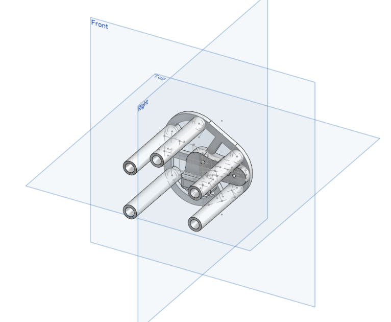
- Today, I designed the wrist joint in CAD, which will hold the 4th and final stepper motor for the claw. This design should not have taken me as long as it did. Still, I was determined not only to ensure the stepper fit well but also to make the design appear polished and sleek while maintaining proper tolerances on these parts and, once again, allowing for room for any wiring. I also made sure to consider how the parts would be installed so that the construction would be easy. Below are images of the two parts of the wrist for both females and males.
June 20, 2025 - 5 hours
What we did
Philip
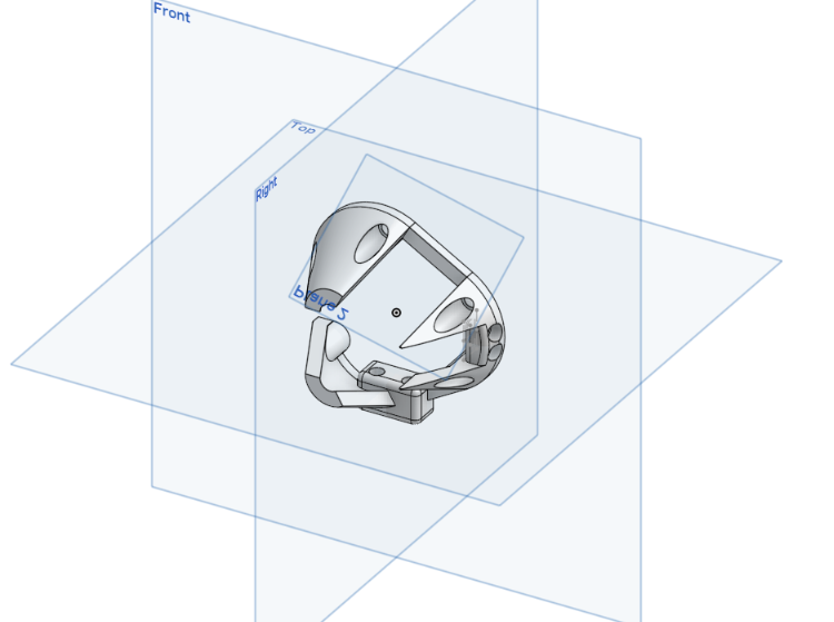
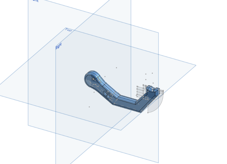
- Today was my final day of designing the CAD model; I finished completing the models of the upper and lower claws and finally assembled all the pieces into one. I learned a lot about effective ways to create CAD models of very different shapes, as well as what it means to design a project in CAD from start to finish. While I enjoyed this process, after pouring so many hours into it, I am glad to be done. Below are images of both pieces of the claw as well as the whole assembly.
June 21, 2025 - 1 hour
What we did
Ruzanna - Today I organised the folders of the repository, converted BOM to its necessary format, and double-triple checked meeting all the highway submission requirements, making the necessary tweaks!
June 24, 2025 - 8 hours
What we did
Philip
- Today I designed and implemented the complete web-based control interface for the robotic hand. First, I wrote the HTML, CSS, and JavaScript UI that the ESP32 will serve to a browser, adding buttons for each joint and a live force readout. Next, I encapsulated that interface in a mainpage.h header using PROGMEM so the ESP32 can efficiently host it. Finally, I developed the Arduino sketch: it connects to Wi-Fi, starts HTTP and WebSocket servers, parses JSON commands from the browser to drive the A4988 stepper and four servos, and periodically reads the HX711 amplifier to convert the raw load-cell output into newtons and stream it back to the client in real time. Below is a pricture of the HTML webpage.
<img src="Progress Images/ArmControl_Webpage.pngwidth=
400"/>
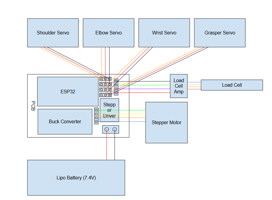
- I completed the overview wiring diagram, which shows how all the electrical components, except those inside the PCB whose wiring is detailed in how the schematic, will be connected. Most notably, it shows how the four wires from the load cell will connect to the amplifier, which was previously not shown in the schematic.
July 5, 2025 - 10 hours
What we did
Philip
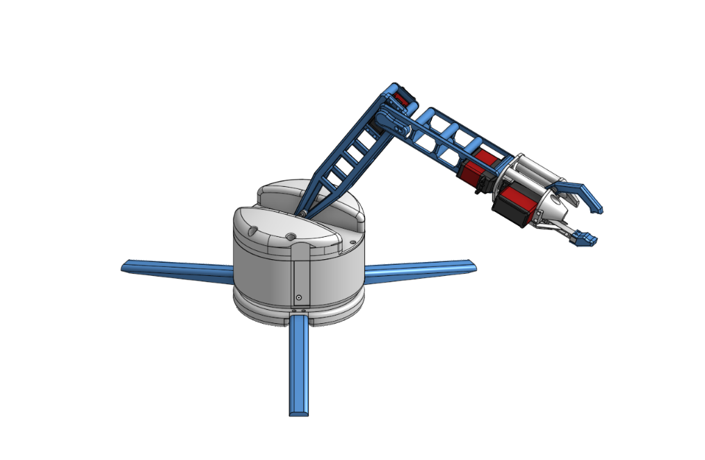
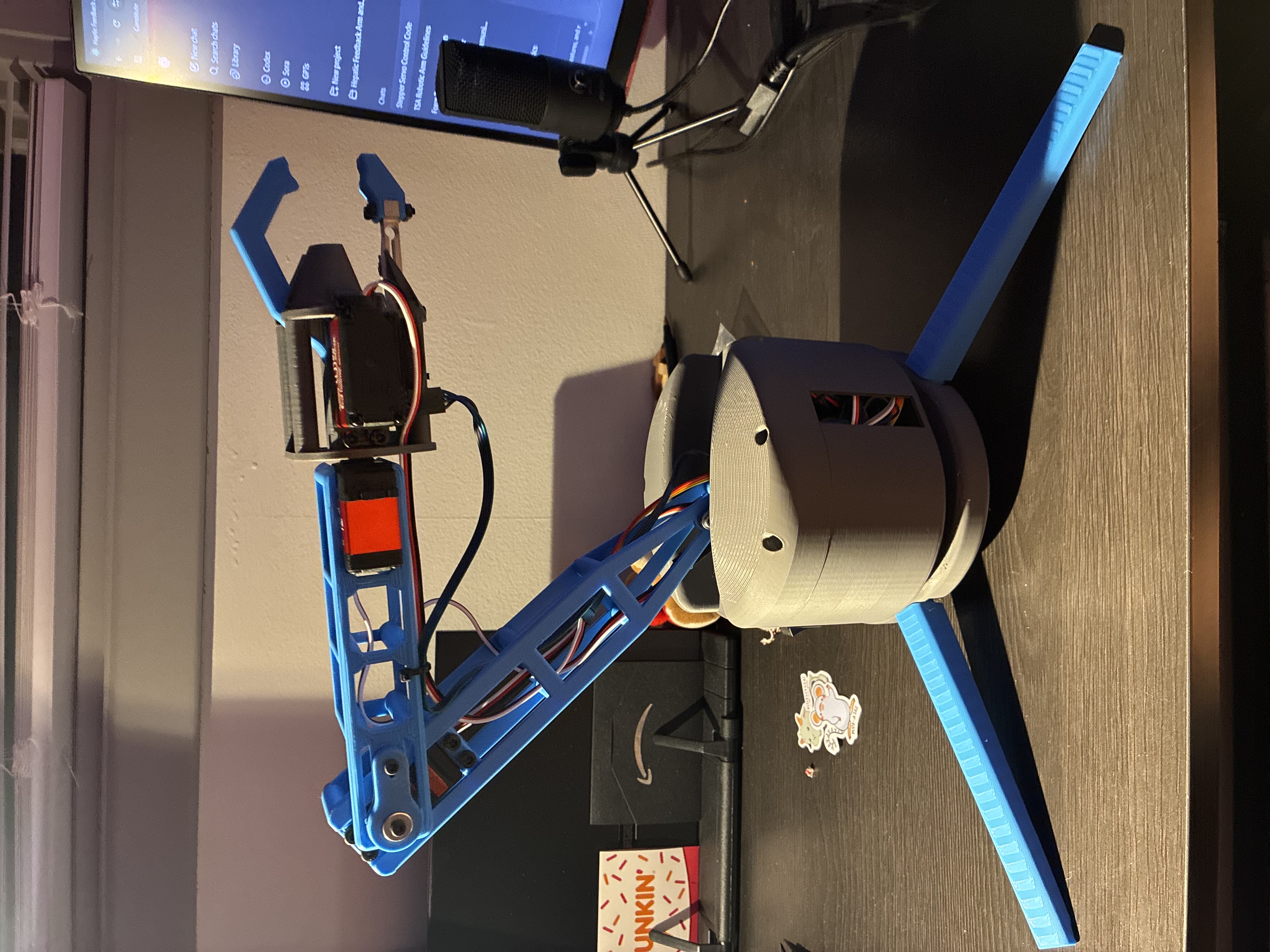
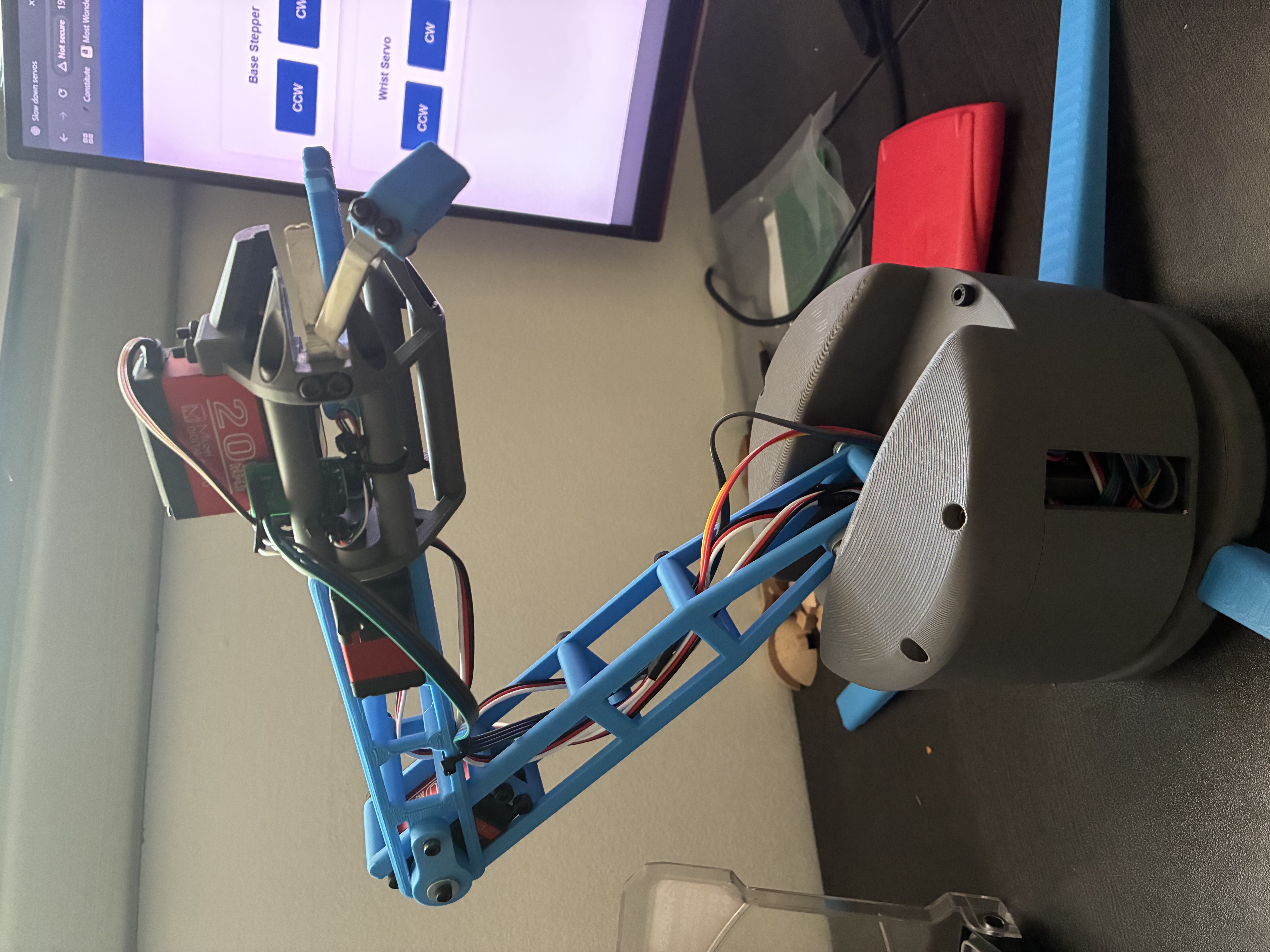
- After our project was approved and the funding was secured, I ordered all the required components for the build. While waiting for the shipments to arrive, I 3D-printed all the structural parts for the arm. Once the components arrived, I assembled the robotic arm, including precise alignment of the joints, mounting the servos, and integrating the load-bearing sections. I also soldered and connected all electronic components to the custom PCB, ensuring proper routing and cable management. Below is a picture of the fully assembled arm:
July 10, 2025 - 3 hours
Ruzanna - I worked on soldering electronics today! It was a bit tricky at first, but I’m getting better at making clean connections and figuring out where everything goes. I’m starting to feel more comfortable using the soldering tools and fixing little mistakes when something doesn’t connect right. This was my third soldering attempt!
July 11, 2025 - 4 hours
Ruzanna - While we were waiting for Undercity to Kick-off, we decided to continue working on assembling the arm at GithubHQ! It was a fun and productive way to use the time and we really appreciated the peers who stopped by to check out our project and offer help. Their interest meant a lot and even helped us catch a couple of things we hadn’t noticed.
- After putting most of the arm together, we started testing and debugging our code for the arm, which was one of the most challenging phases of getting the arm to work. Even though the hardware was mostly in place, the arm didn’t move the way we expected at first. We had to go through the code, check how each motor was responding, and fix issues with timing and control signals. It took a lot of trial and error...
August 5, 2025 - 8 hours
What we did
Philip - I spent the day updating and refining the robotic arm’s control code. Throughout July, I had been intermittently working on improving the arm’s motion, but today I implemented several new features and focused on smoothing out the movements. I also added functionality that allows the arm to remember its last position and automatically return to it upon power-up, improving both usability and safety.
August 6, 2025 - 8 hours
What we did
Philip
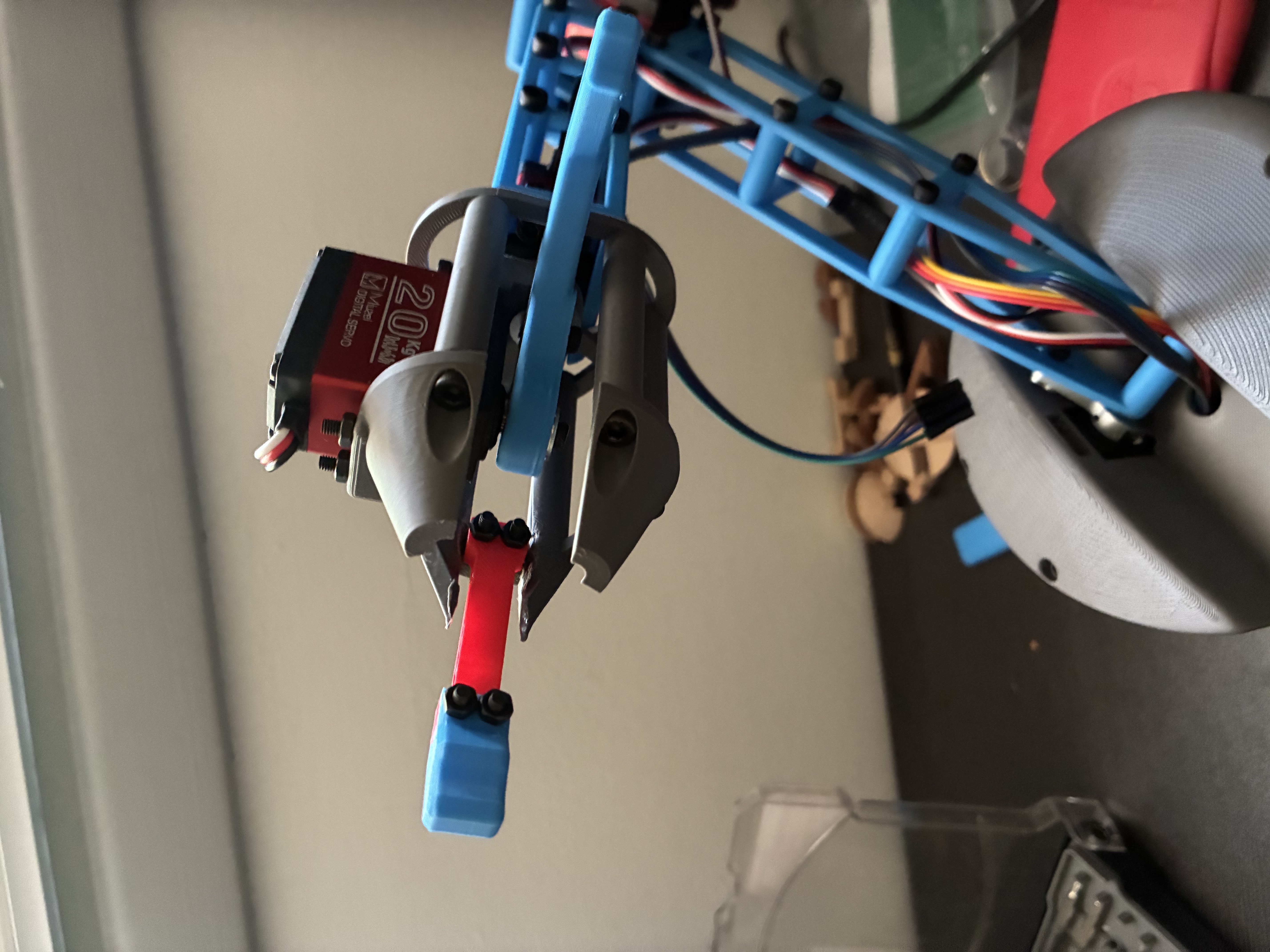
- Today I continued improving the control code, primarily focusing on calibrating the load cell to ensure accurate and stable readings. Unfortunately, during testing, one of the safety constraints on the grasper failed, causing it to over-rotate and break the load cell. I temporarily replaced it with a 3D-printed substitute (pictured below along with the damaged load cell).
- Despite the setback, I was able to correct the motion issues, complete testing, and successfully record a demonstration video, which is linked below.