
Total Time: 116 hours
May 15th: Started work!
Cooked up my idea and started researching the parts lying around in my kit and the school shop.
Time today: 1 hour
Time total: 1 hour
May 17th:
Okay so basically I set up the platformio dev environment and got my esp32 driving an MG996R stepper motor.
https://github.com/user-attachments/assets/8cf88195-3297-4feb-9b49-cdf6550582a8
I've been wanting to create something like this for a while and I bought these components several months ago but never got around to seriously starting work on it. (And now it looks like Purdue beat me to it lol.)
Anyway I think the best way to properly begin this is to setup some goals for Cuber: - Create an automatic motorized Rubik's Cube solver. - Have it automatically detect the initial state of the cube using colour sensors. - Implement an algorithm like Kociemba's to solve the cube. - Have an automatic scrambler to allow continuous action. - 3D print a custom case to house components, that allows for easy access to the cube.
Wow that is a lot of goals haha.
To keep the kinematics of the cube simple, I will use a similar approach to the students at Purdue and MIT: 6 motors, one for each face of the (no full cube rotations). To allow for access to the cube, I will allow the housing for each motor to swing out like a flower, letting me swap the cube in and out.

I got 6 TCS3200 colour sensors from my school, and the idea is that one could cover each face of the cube on the corner, and rotate the face at 30° intervals to detect all 12 stickers.
I then imported the MG996R into Fusion 360 and designed a pinion for the Rubiks cube. It will drive the cube sides by slotting into the middle piece. This is when I realized that the motor spline is to small for my 3D printer to print. Instead, I will use the injection molded pinion that came with the motors, and probably superglue the pinion to it or smt idk.

Time today: 4 hours
Time total: 5 hours
May 19th:
Spent like 30 minutes today trying to make PlatformIO actually useable.
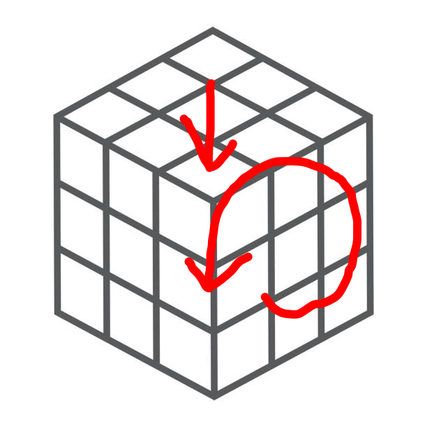
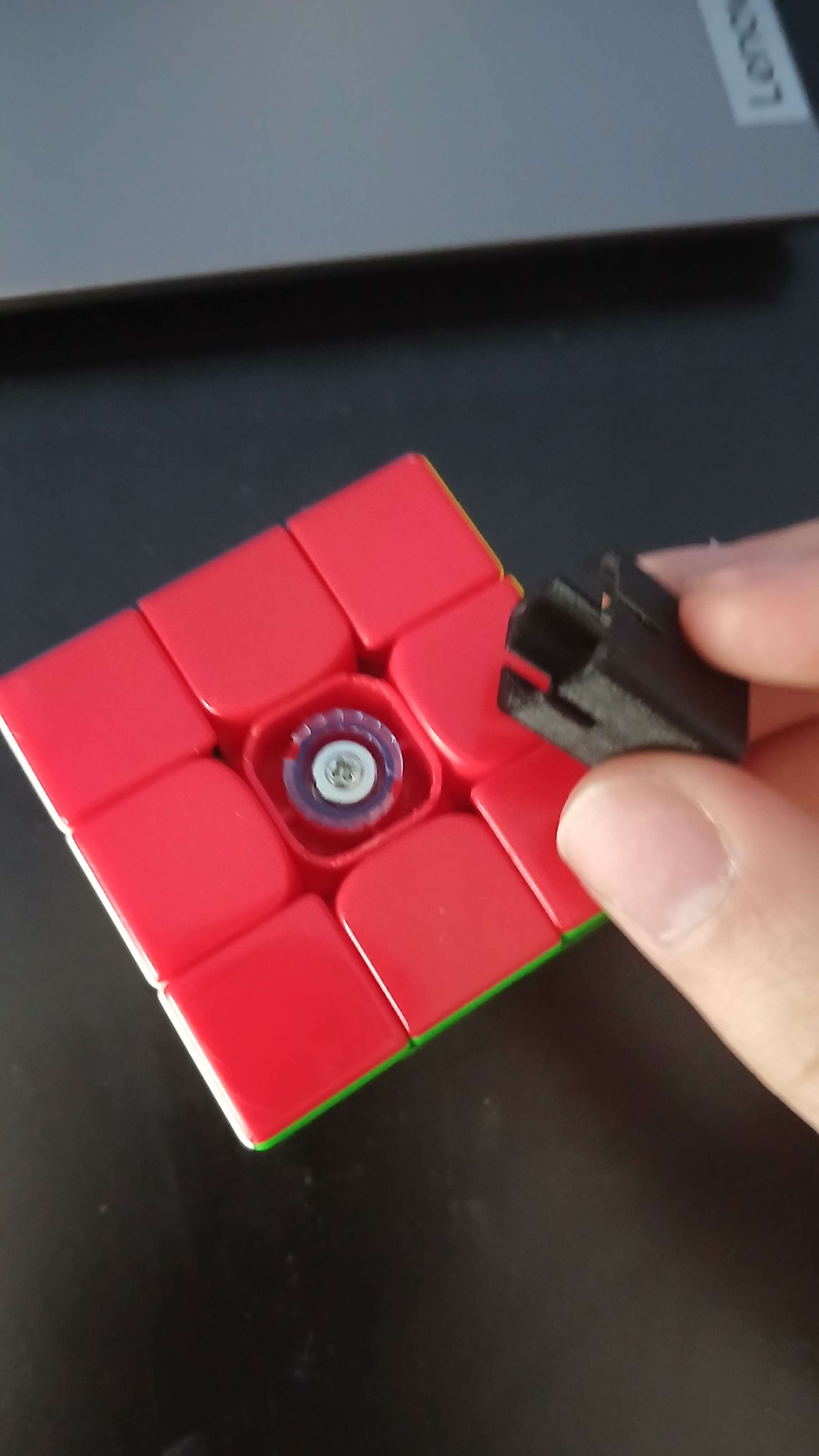
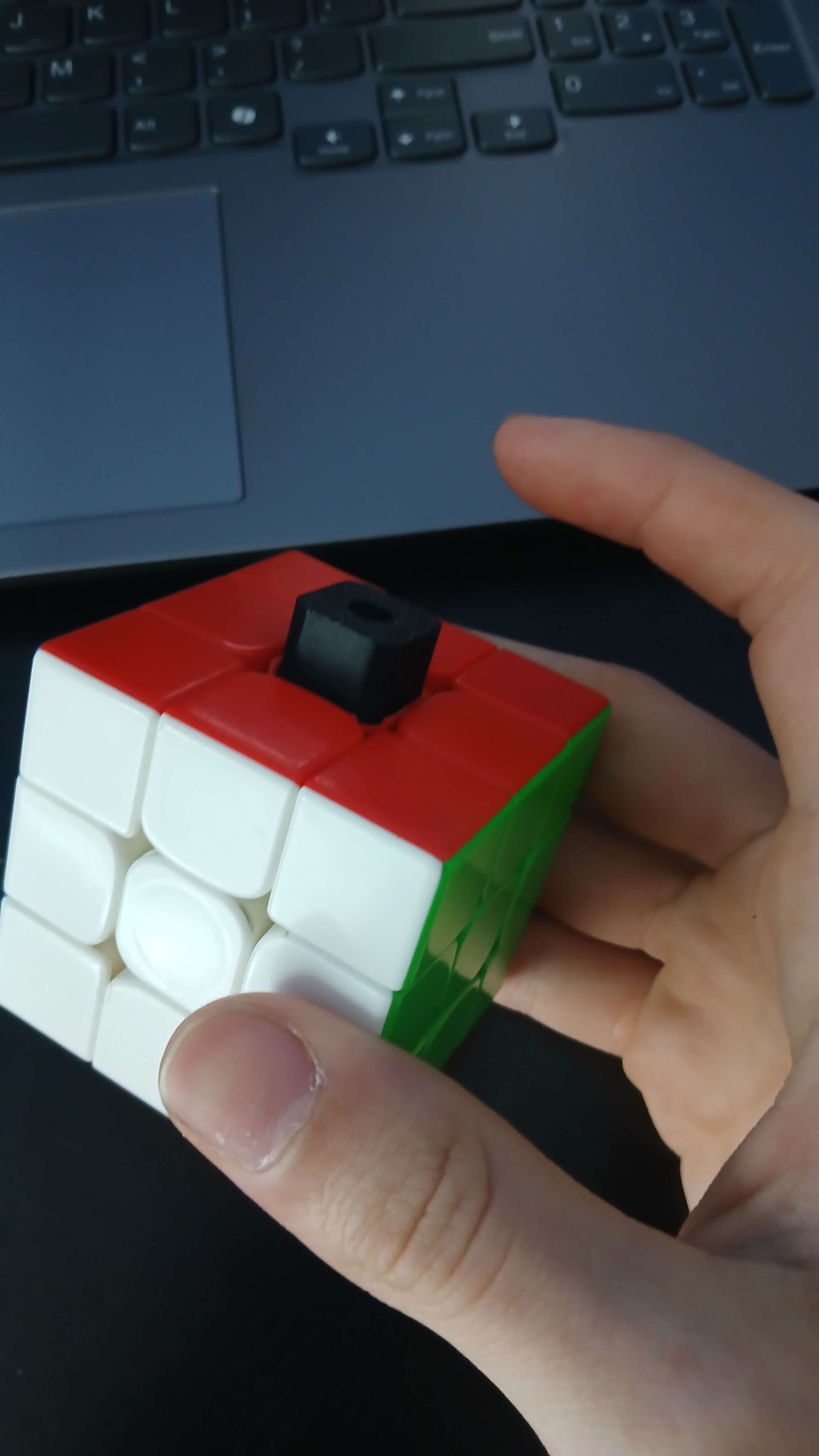
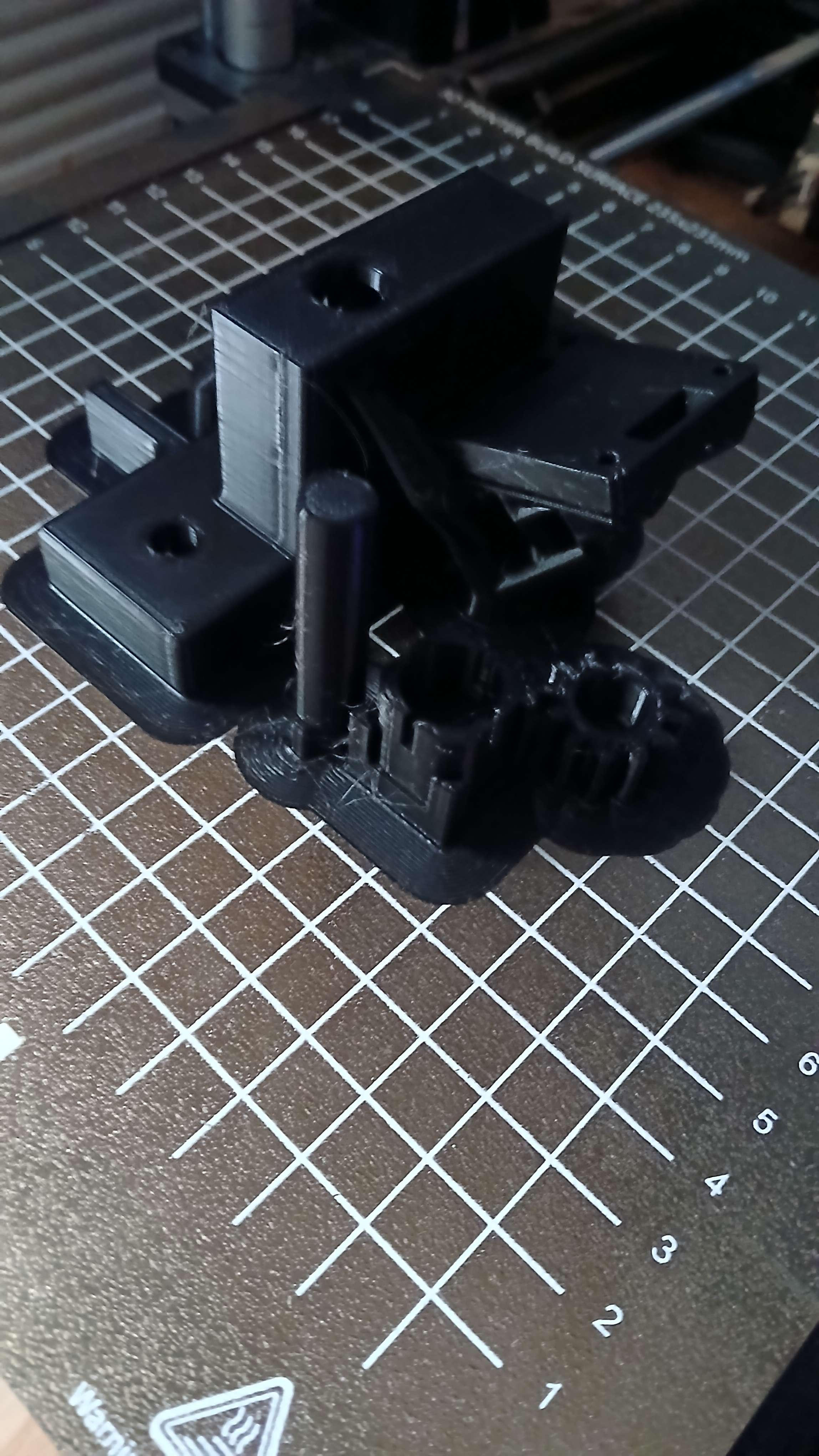
I played with my prototype pinion a bit and learned that I need to apply a ton of normal force to allow the sides to rotate.
No force (top) vs. force (bottom)
https://github.com/user-attachments/assets/cadc4695-f0eb-4065-a3e3-c17ea3f0df7f
https://github.com/user-attachments/assets/0a5ce550-07eb-4adf-b740-79804e6239e9
I will need to loosen my cube a lot for this, but not so much that it explodes in your face. Lubricant is also needed, I don't know what type to use though. I can buy some specialized stuff from SpeedCubeShop or just douse the cube in some machine oil from my school's shop lol.
I haven't had a lot of time these past couple days but hopefully I will have some more soon!
Time today: 1 hour
Time total: 6 hours
May 23rd:
Finally got some spare time! Jumped into Fusion today and designed a prototype gearbox for the motor & pinion.
Because the version of the MG996R I have has only 180° of rotation, I need to make a step up to allow for full range of motion. I went with a 1:2.5 gear ratio via a 30T pinion and a 12T gear. Not gonna lie the MG996R has a ton of torque—I did the math from the specsheet and I could go up to like 1:8 or something.
Anyway, the 1:2.5 ratio works as all of the angles I need are whole numbers.

I'll be able to 3D print this over the weekend and test it out. If it works, I'll be able to attach 6 of these together to create a full robot. I'm still thinking about how to get the cube in and out though. The flower idea I mentioned early is probably too complex. I'll maybe make the top motor attached via a bolt that you can screw in and out.
But now that we know we need a large normal force, we may have difficulty getting the cube in and out. When I have time I'll fiddle around with my pinion and see how much play there is and if it would be possible to twist the cube out. Otherwise we may need multiple motors to be unscrewable.
Time today: 2 hours
Time total: 8 hours
May 24th & 25th:
Printed the gearbox. Turns out I suck at superglueing stuff together. Note to future self: sand the prints before gluing lmao.
Got it rotating and stuff. But I'm browning out the ESP32 on just a single stepper motor. Tomorrow I'll be able to take it to school and test it with an actual power supply.
https://github.com/user-attachments/assets/a11832de-1fdf-4844-b957-5d1f5c20488e
Time this weekend: 4 hours
Time total: 12 hours
May 30th
So whats up. I tested the jig with a power supply and theres a couple things I learned: - I need to make it stiffer so that the gears dont twist out. - I suck at estimating tolerances.
For most of my testing time, the pieces of the cube were catching on each other, so I had to tighten the cube faces down. It was able to rotate the sides of the cube, but it was quite innacurate due to how much tolerance there was in the pinion and the gears.
I originally created a glue down cover for the pinion to rotate in, but my friend suggested that I make the shaft slide in and have the pinion be press fit.
Time today: 1 hour
Time total: 13 hours
May 31st
Printed some tolerance tests. - Print in place: 0.5mm - Print out of place: 0.5mm - Press fit: 0.3mm
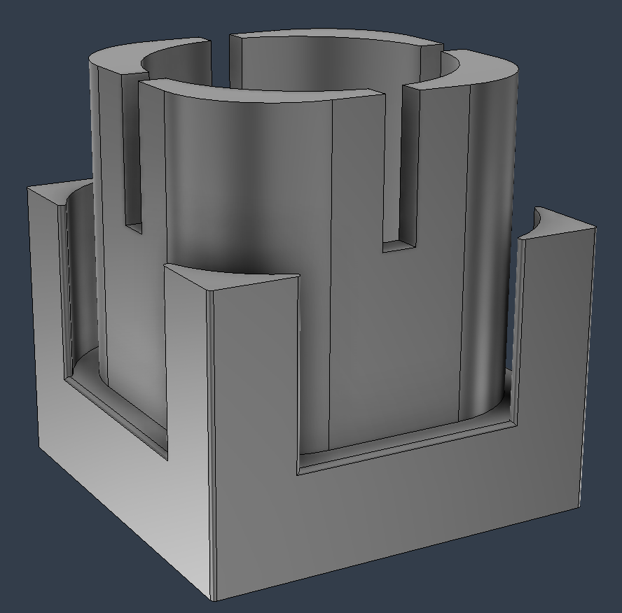
Also designed a new pinion to better fit the cube. Reduced the tolerance between the pinion and the walls of the piece, and made it wrap around the corners. Not sure if the corner pieces actually do anything but maybe it increases the torque lever arm 🤷♂️.
Time today: 3 hours
Time total: 16 hours
June 1st
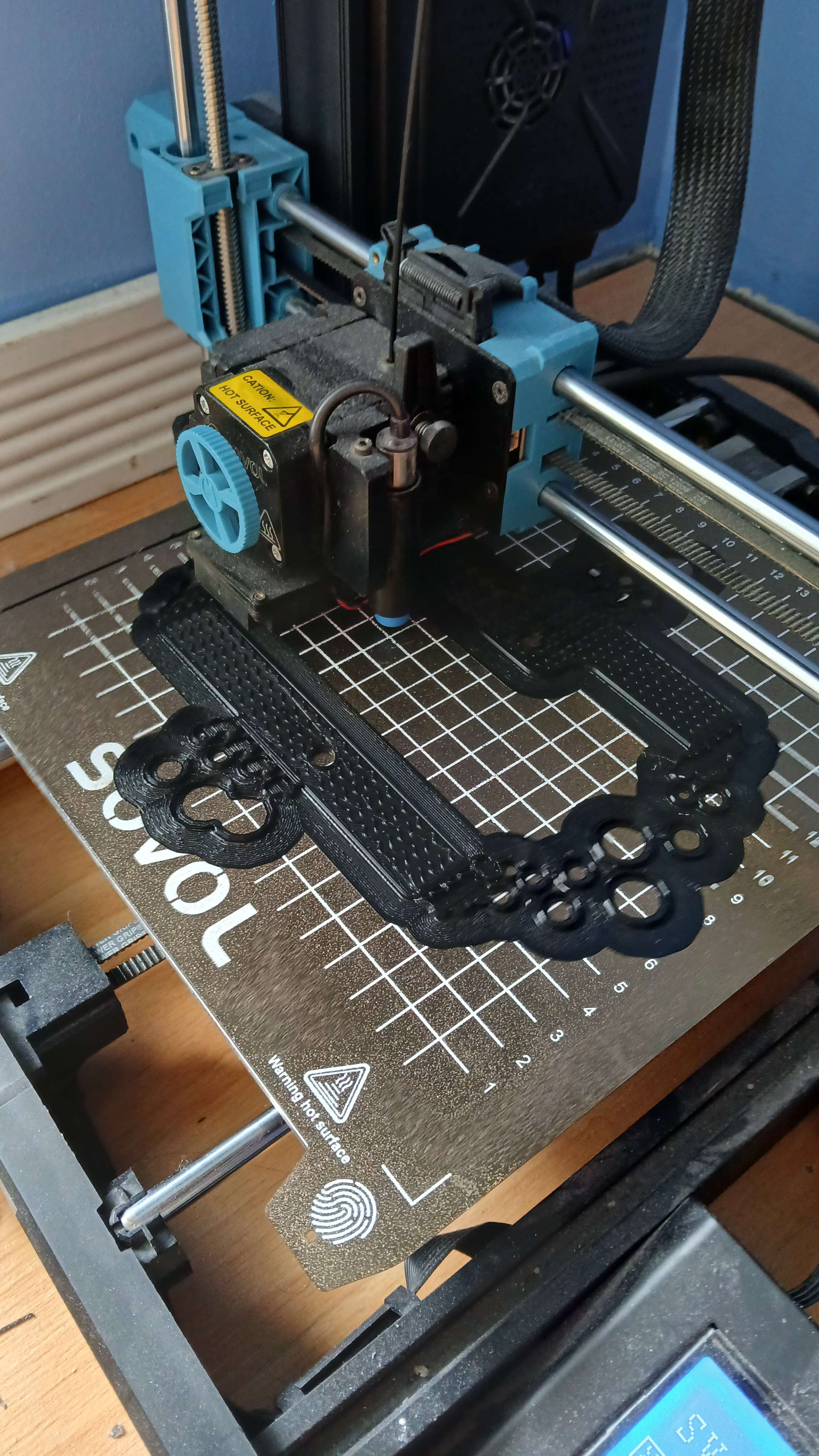
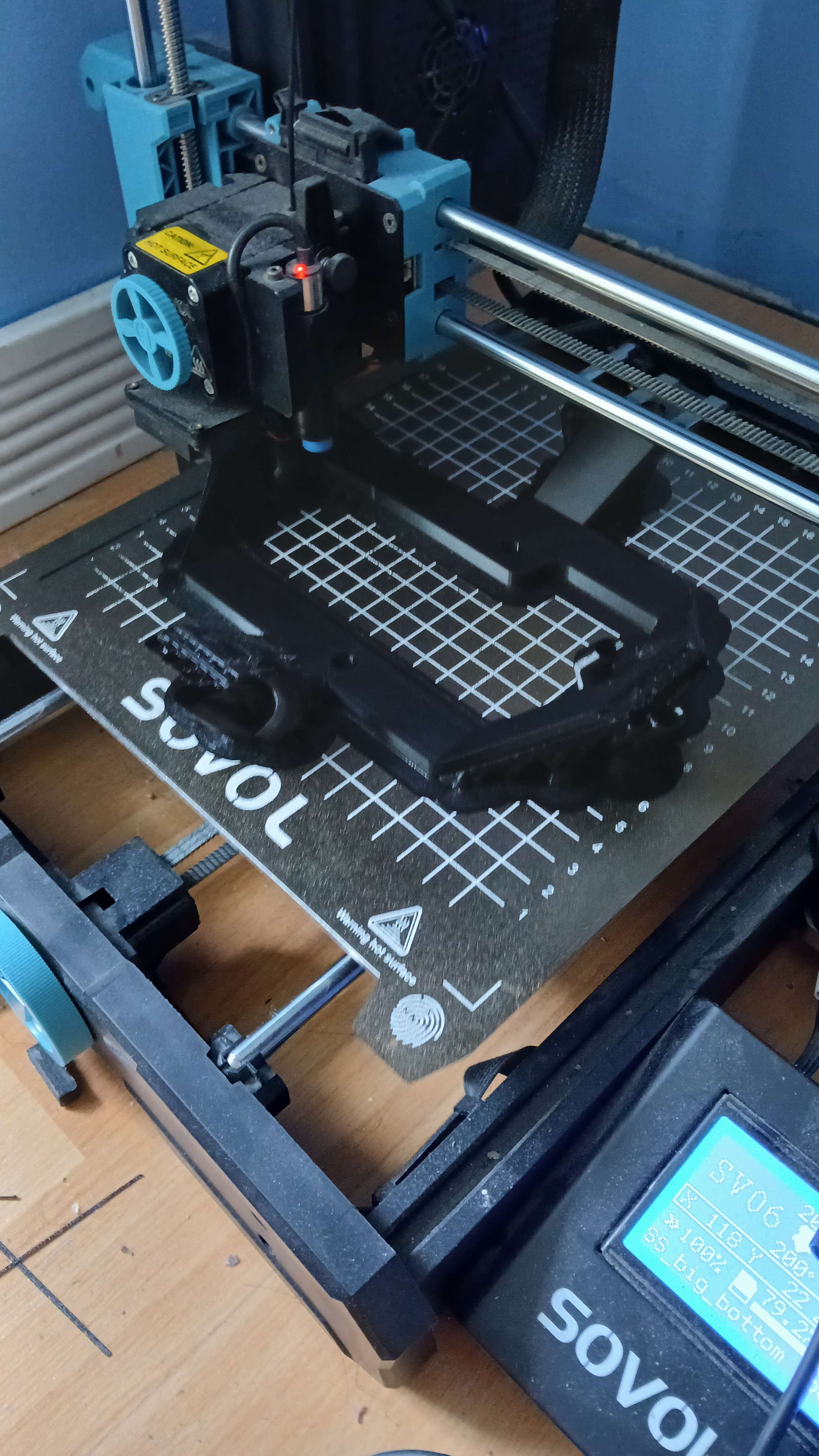
Printed out the new gearbox and assembled it together. I need to update it a little as its too close to the face of the cube and the other sides of the cube can't actually rotate lol.
Time today: 2 hours
Time total: 18 hours
June 2nd
Brought it to school and tested it out. Works much better with a lot more backlash. I can still reduce the last bit of it by adding a shaft to the pinion gear, keeping it from rocking side to side. Other than that, its pretty sweet. Something I've noticed is that for some reason the motor isn't linear. 0-90 is the same as 90-180, but 180-270 is much smaller. All stuff that can be changed in software.
https://github.com/user-attachments/assets/d39e9d64-2d36-401b-b0da-273edd4b6365
Hopefully v3 will be the final version of the gearbox. Once I confirm that works then I can start cadding the full assembly.
Time today: 2 hours
Time total: 20 hours
June 6th
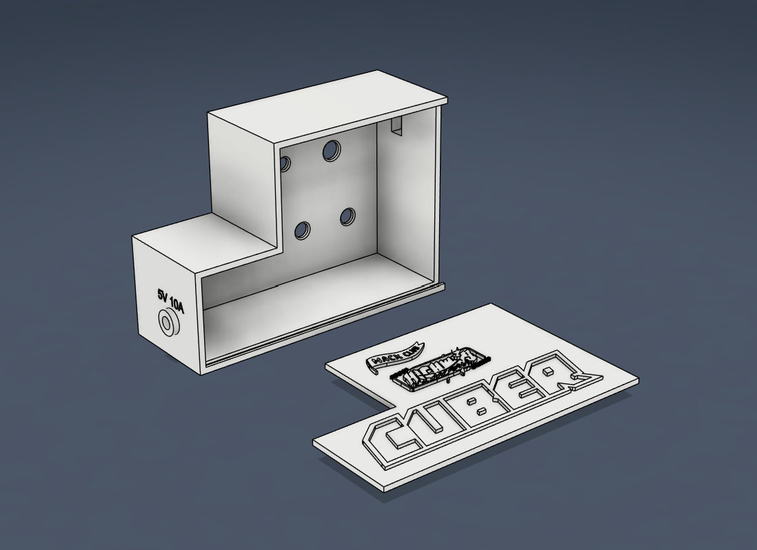
Spliced this power supply to power my esp32 and motors. It's 5V 10A, and each motor draws 2A maximum. Hooked it up and it works! I also looked into the specs of the jumper wires I was using and i could power up to 2 motors at a time. (22 AWG, 4A).
.png)
Time today: 1 hour
Time total: 21 hours
June 7th
Started playing with the colour sensors. I tried using a library and wasted hours getting it to work. I instead settled to just doing all the fancy stuff manually. I got it able to differentiate between red, green, and blue, but I really need to calibrate the values and tune the thresholds it if I want accurate colours. I think I might need to do this for all 6 sensors.
Colour sensors pmo.
Time today: 4 hours
Time total: 25 hours
June 8th
Dude the colour sensor works. IT WORKS.
I took min and max values for red, green, and blue, and then used this funky map function I found to map it to 0-255. I then used colour normalization to get the ratios of the colours (brightness independent). I then measured each side of the cube, getting the RGB ranges from right up against the cube to about 2 inches away. I could then just iterate over all my colours to find out which RGB band it falls into.
So excited to get this working. I will probably have to recalibrate it when I make the assembly, and also do it for 5 other sensors :(
However, now I know how to do it, so it should be faster next time!
From now I want to focus on integrating a sensor mount into the gearbox, and combining everything into a single 6 motor assembly. I will probably also have to make a wiring diagram. These colour sensors require a lot of pins, (5 exactly) but two of them (the ones that set the frequency) can be shared across all of them, saving 10 pins.
https://github.com/user-attachments/assets/c96f8a81-6cd7-4bb0-83de-4ab9377df998
Time today: 2 hours
Time total: 27 hours
June 9th
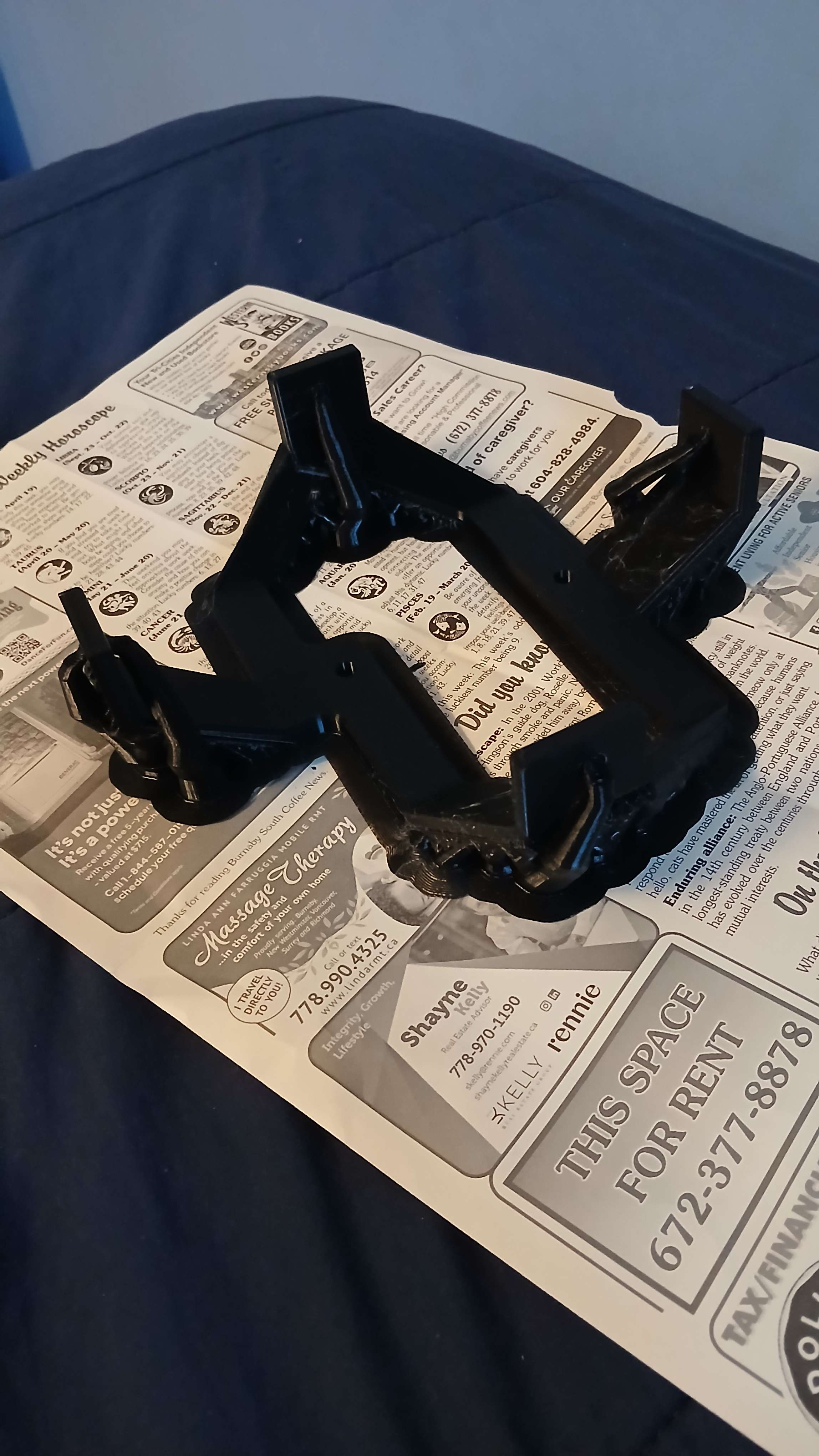
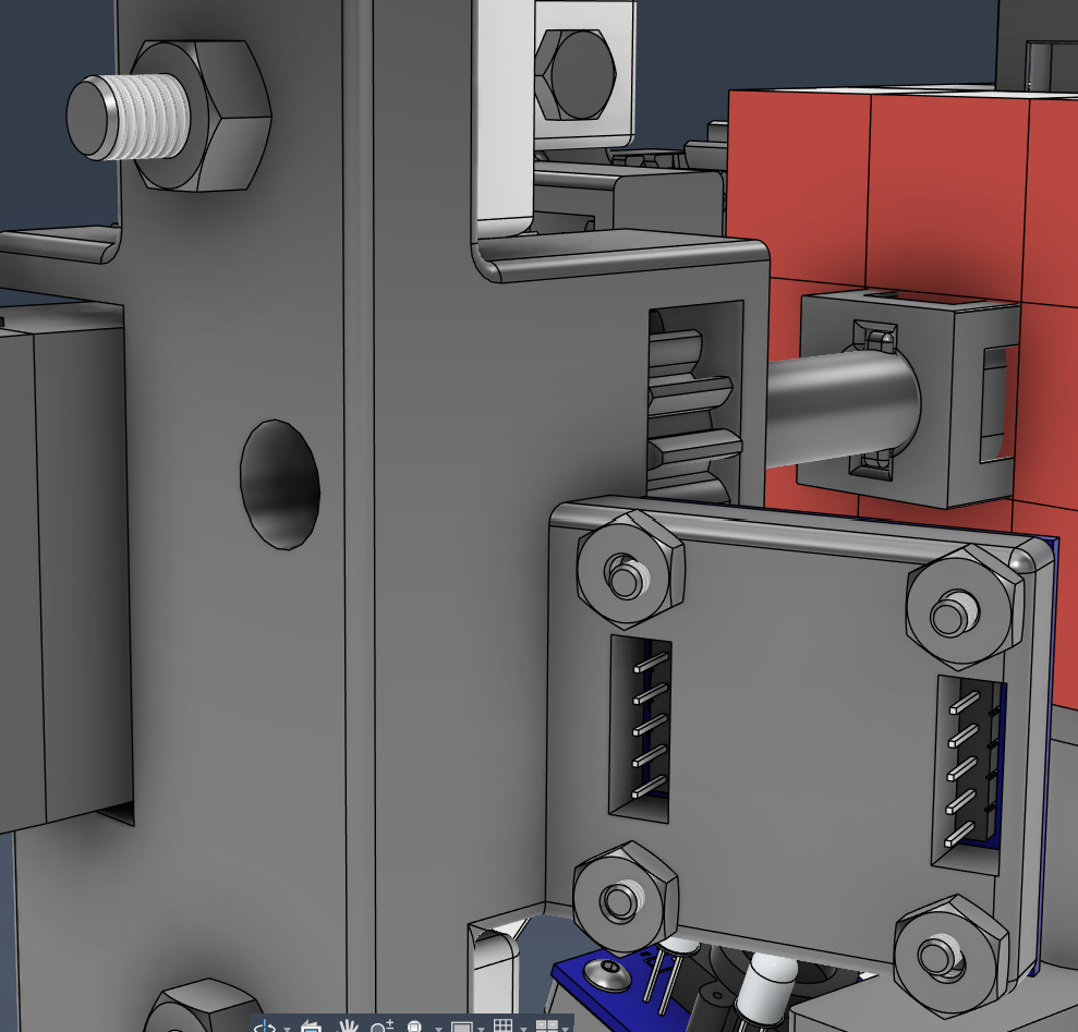
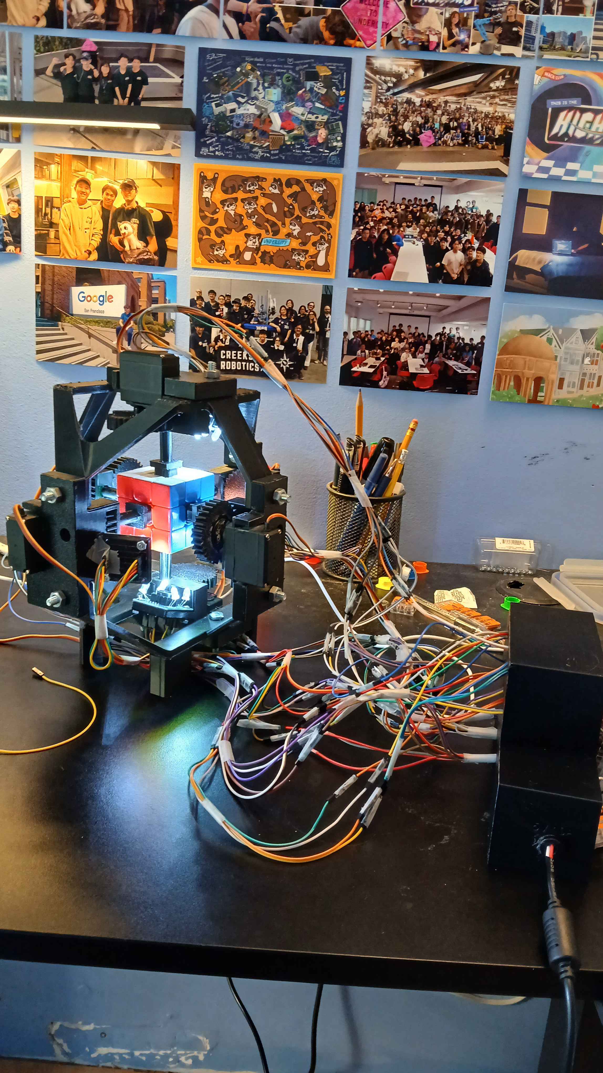
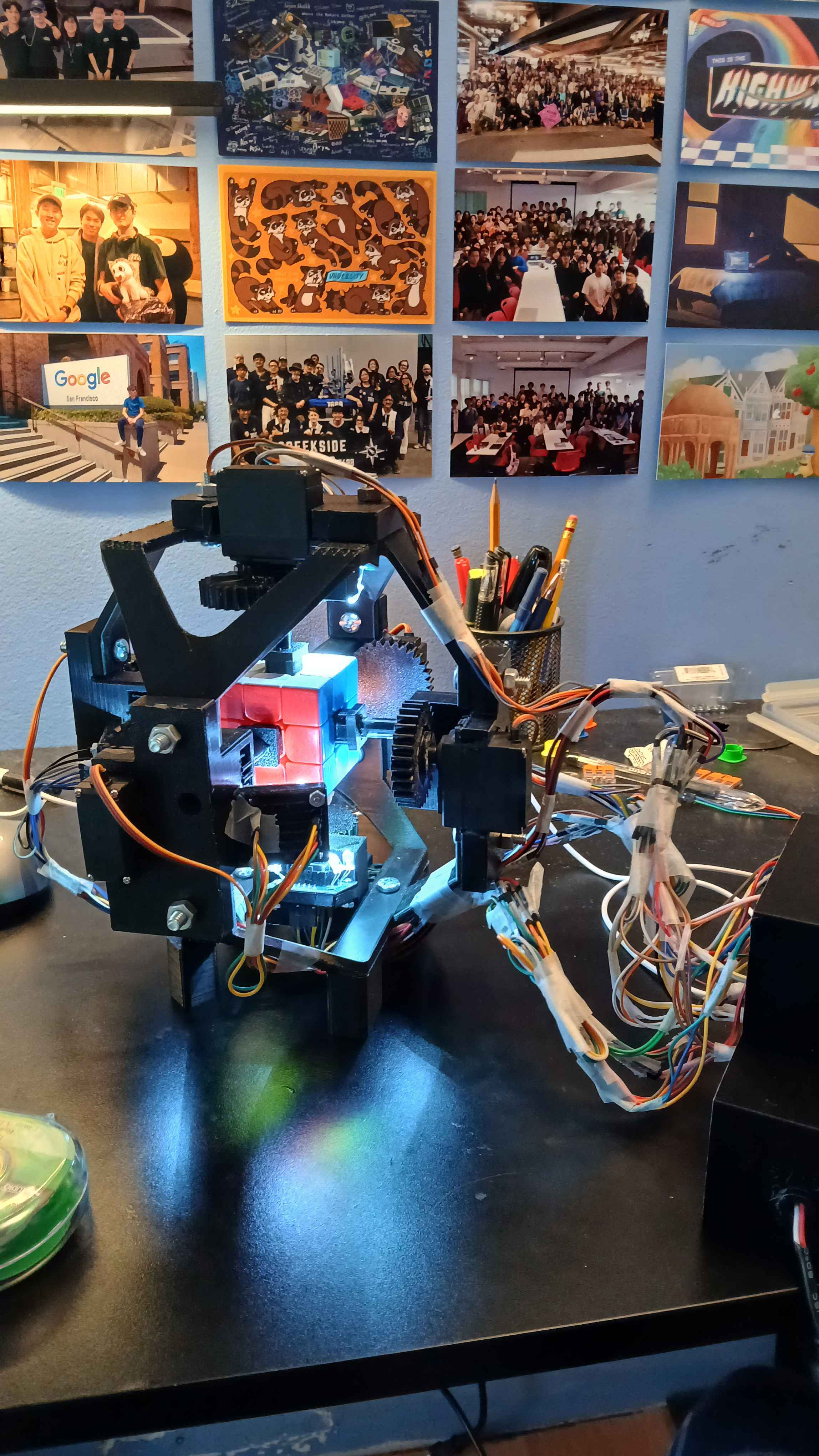
Extended the drive shaft so that the cube wouldnt be blocked by the gearbox when turning. Added a mount for the colour sensor to the gearbox. I then also added some mounting holes and arranged the 6 gearboxes into an assembly.
It's really coming together!
I need to make the net
that connects the 6 gearboxes together. The net will go on the inside of the gearboxes so that you can undo the bolts and just take them out without any maneuvering I also want to figure out how to make the wiring nice. It's gonna be so cooked because of how much there will be. I need 8 wires per gearbox (48 total) + more for splitting my power and ground. At the bottom of the assembly I can make a case for the ESP32. It might even be a good idea to make some buttons for control (start
, stop
). But yeah. It's gonna be so good.
.png)
.png)
Time today: 4 hours
Time total: 31 hours
June 10th
Holy lock in.
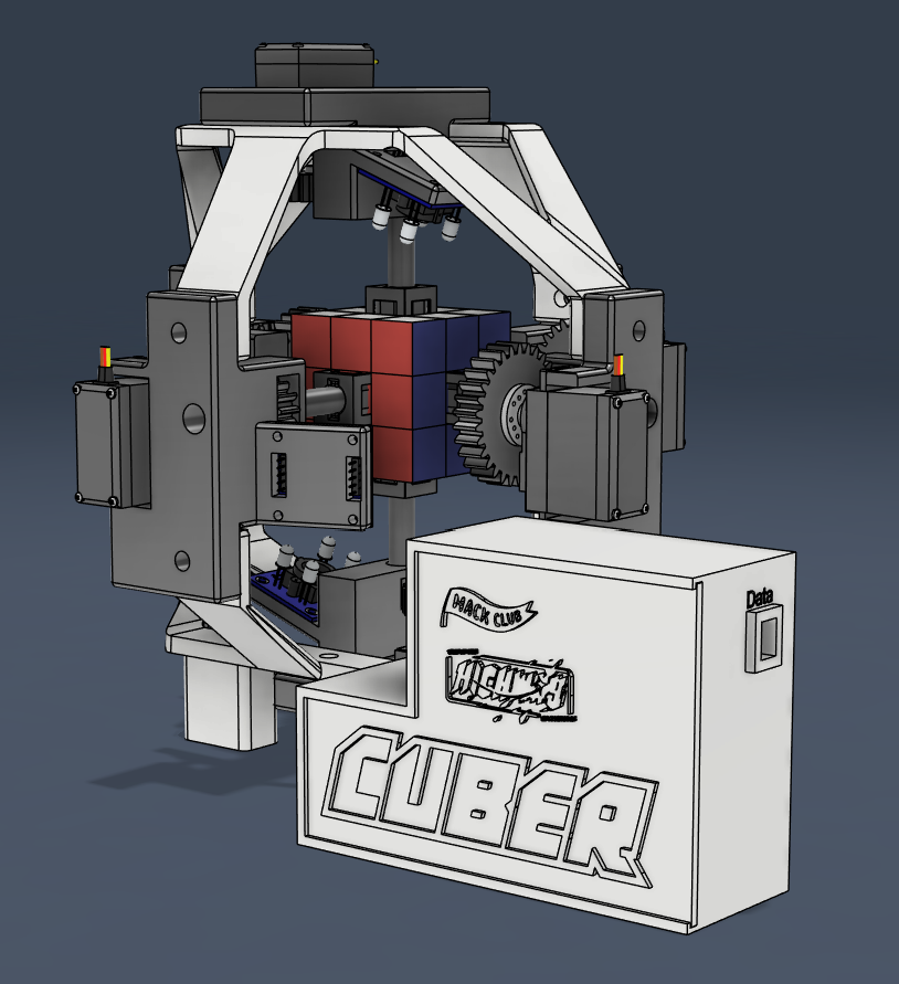
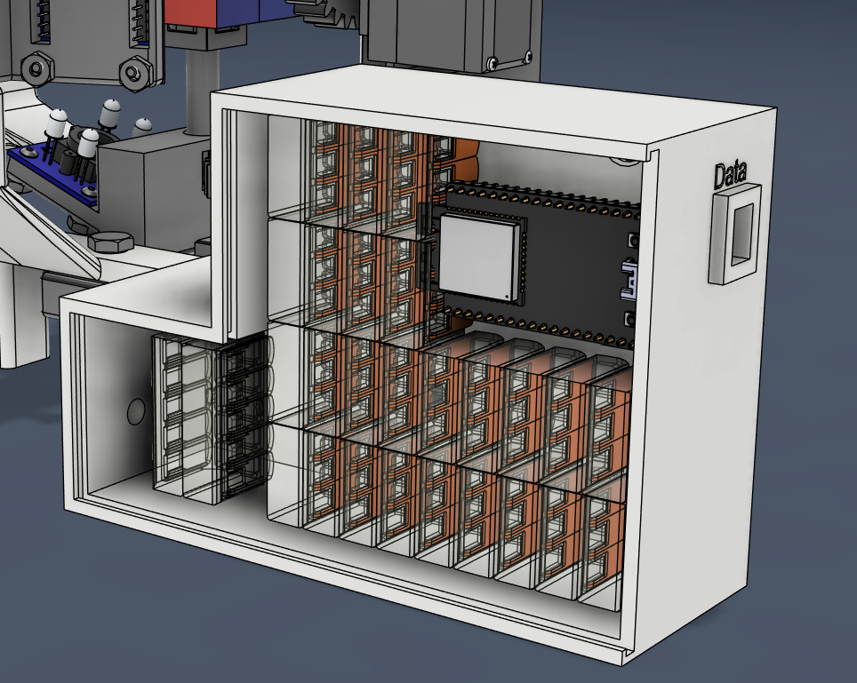
Made some nets
that connects the gearboxes together, and a box to store all the electronics. The gearboxes mount to the net via 1/4-20 bolts, and when you unscrew them you can just take it right out with minimal fuss.
The CAD is mostly finished at this point. I had to make a few small modifications to get the colour sensor to fit.
I then made the wiring schematic in Fusion. It turned out a lot cleaner than I expected, but jesus it is a lot of wires. There will be lots of splicing and soldering to do for VBUS, GND, and sensor pins.
.png)
.png)
Time today: 7 hours
Time total: 38 hours
June 11th
Printed a gearbox. These take a lot of time lol. Cleaned it up and removed the supports, then assembled it.
Time today: 1 hour
Time total: 39 hours
June 12th
Printed another gearbox lol. I can really only print one a day because I like sleeping too much.
Time today: 1 hour
Time total: 40 hours
June 13th
Yo so basically I goofed up in the CAD. Turns out the pinion was pressed further into the gear than I thought, so I made everything too close to the cube (As I was assembling the gearboxes with the shaft pressed perfectly into the gear). I had to spend some time modifying the nets to reach out a bit further (0.225") in each direction so that everything would fit. But now it's all good! I'll be able to get a bunch of printing and assembly done this weekend.
Time today: 2 hours
Time total: 42 hours
June 14th
Printed 2 gearboxes.
June 15th
Printed another gearbox lol.
June 16th
Printed the final gearbox. I also printed some of the gears but that will take some time.


Yo so I did a bunch of boilerplate code for the colour sensors and servos. It's all placeholder values as I can't actually get the real constants until it is fully built.
The plan right now: - Print gears - Glue pinions to servos, and servos to gearboxes - Print the nets - While printing, write colour detection algorithm and implement Kociemba's - Assemble the entire thing - Wire it up & test functionality of each motor and sensor - Calibrate the sensors - Calibrate motors - Test it!
Time today: 4 hours
Time total: 46 hours
June 17th
Yo so I printed the gears 👍
Time today: 1 hour
Time total: 47 hours
June 18th
I printed the bottom net. It took 12 hours but it's done! Looks great and it's fairly stiff so it won't flex under the weight of everything.
Time today: 2 hours
Time total: 49 hours
June 19th
Me when I forgot to order new filament.
New roll isn't coming until tomorrow. I did get my connectors and wires though so I can start splicing stuff.
Time today: 1 hour
Time total: 50 hours
June 20th
LAST DAY OF SCHOOL
Anyway Kicad is so much nicer than Fusion 360 wtf. Made this cool new thing that's so much more readable.
.png)
Time today: 1 hour
Time total: 51 hours
June 21st
I got the filament! Currently printing the top net. I also assembled most of the robot and have attached all the colour sensors. I'm still relaxing from school so I'm not really working that much today.
Time today: 2 hours
Time total: 53 hours
June 23rd
Code cleanup. Lowkey forgot the include folder was a thing so I moved all my headers into it.
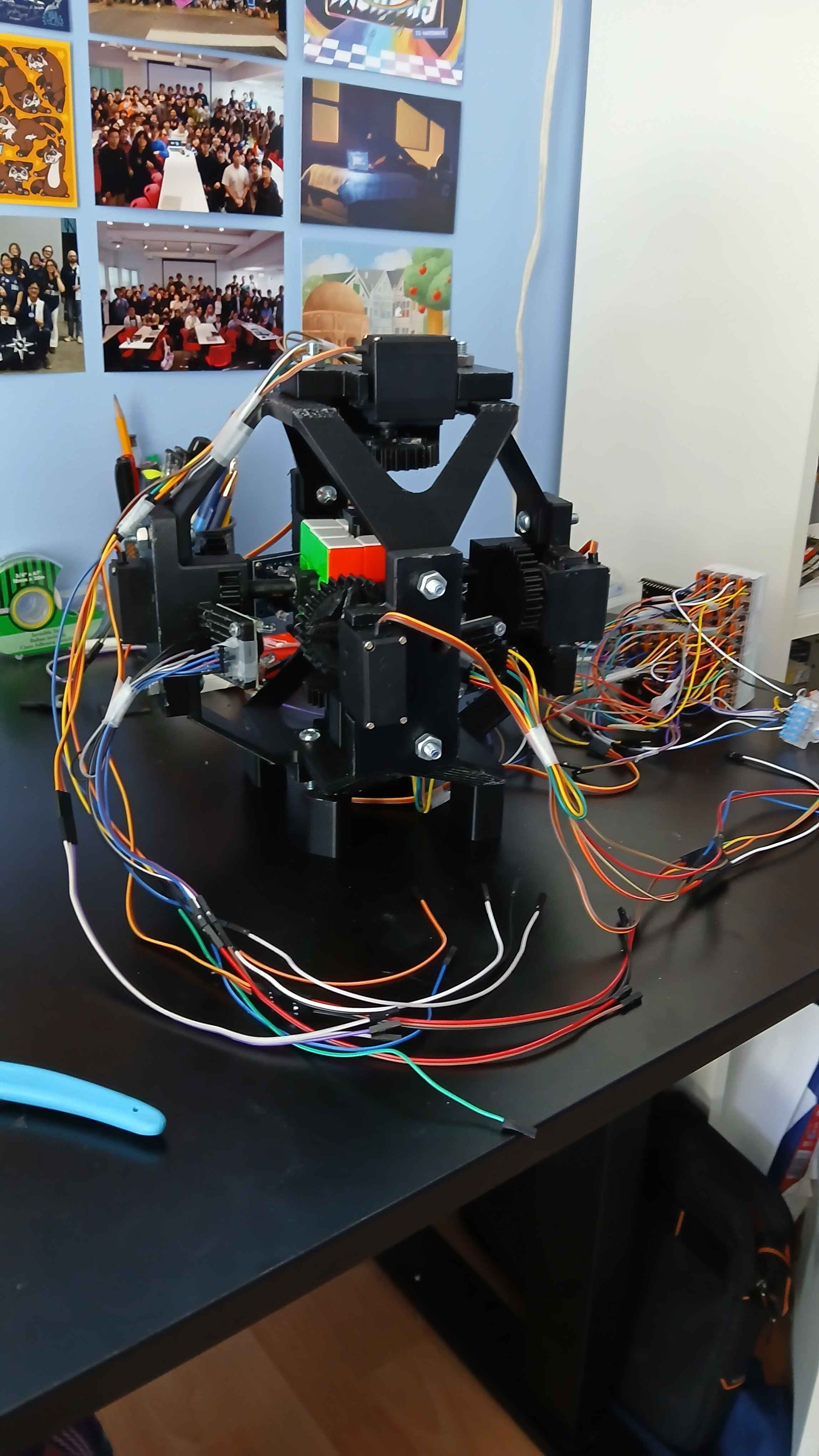
I then got to work wiring! I found out that I don't need to splice wires to put them into the lever nuts. I hooked up 5V, GND, & PWM for the servos. I still need to wire all the signal wires for the colour sensors.
Wire management is currently a future me problem.
https://github.com/user-attachments/assets/b7c72ac2-09a4-430d-928e-34b1d36eac41
Time today: 4 hours
Time total: 57 hours
June 29th
Got to work testing the servos via code and making sure they all ran.
Time today: 2 hours
Time total: 59 hours
June 30th
Completely overhauled the pwr and gnd wiring to make it much, much nicer. I also found out that specifically one of my servos doesn't have enough torque to turn the face of the cube. I've ordered a new one off aliexpress :(
In the meantime, I can emulate the sixth servo by replacing each instance of U & U' in the steps with a specific algorithm that uses the other 5 faces to rotate it. This is how those commercial solvers work. It does cut down on speed, but it will be very easy to swap once the new servo arrives.
Time today: 4 hours
Time total: 63 hours
July 1st
CANADA DAY WOOO 🍁🍁🍁
Anyways got stuff working. Found a workaround algorithm while I wait for the sixth servo to arrive.
I tried porting Kociemba's, but it turned out it to be WAY too big for the esp32. So instead Cuber will have the solving logic run via python on a computer, and then relay the information back via the serial port.
Time today: 6 hours
Time total: 69 hours
July 2nd
I got the first cube solve with manual colour input. 90 Seconds. Pretty good for the first solve with one of the motors missing. I want to aim for sub 20 seconds when this is all done. The next step is to hook up & calibrate the colour sensors.
Time today: 3 hours
Time total: 72 hours
July 13th
Hello from Undercity!

July 18th
Yo so we back on that grind after an amazing weekend at Undercity.
I changed the way I store servo calibrations, so that it is a grid where you can tune the number based on the current position of the servo. ```cpp ServoConfig servoconfig1 = { .axis_positions = { // 0 1 2 3<-To From {7, 50, 85, 126}, // 0 {7, 50, 85, 126}, // 1 {7, 44, 85, 126}, // 2 {7, 44, 78, 126} // 3 }, };
servo.write(config.axis_positions[position][target]); ```
I had to recalibrate ALL of the servos 🥀 but now its working. I had a weird bug where two turns in a row would cause it to fall short of it's goal so I added a turn_180 function that makes it move directly to the target.
Time today: 3 hours
Time total: 75 hours
July 19th
I forgot to mention it yesterday, but changing the format of the servo positions also optimized it, since I could make it move further than it needs to, preventing it from slowing down at the end of a turn. I achieved a 20.5 second solve, down from 80 seconds. My PB is 19.5s, so its very close to beating me. When I fully optimize it I expect solves under 15 seconds.
https://github.com/user-attachments/assets/d1df5046-f138-488e-aadc-6c804b91be19
I spent like 3 hours trying to calibrate the colour sensor. My usual method of taking min and max values of RGB on the red, green, and blue faces wasn't working so I instead tried taking the min and max values across all 6 faces. Was able to calibrate it, but didn't have time to test it yet.
Time today: 3 hours
Time total: 78 hours
July 23rd
I got it to differentiate between all the colours! But it's only 1 sensor though. 5 more to go. I was able to test it and it is able to detect the different squares, but it does need to be semi accurate. Lock in this week will be craaazy.
Time today: 2 hours
Time total: 80 hours
July 24th
Pulled out all of the wires and started final wiring. I RAN OUT OF DUPONT JUMPERS. So I need to go buy more 🥀. I have basically a giant wall of wagos so I think it would be nice to 3d print a case for them. It would also help with wiring as I could label and separate the openings.
Time today: 2 hours
Time total: 82 hours
July 28th
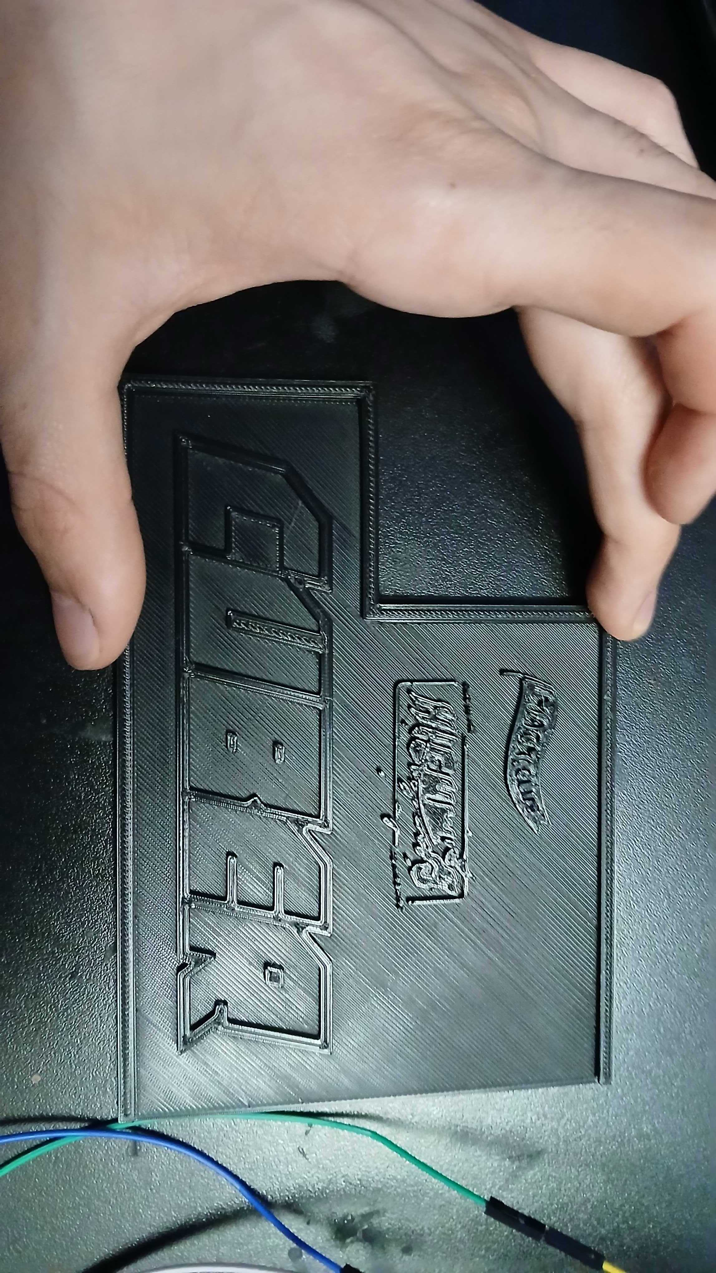
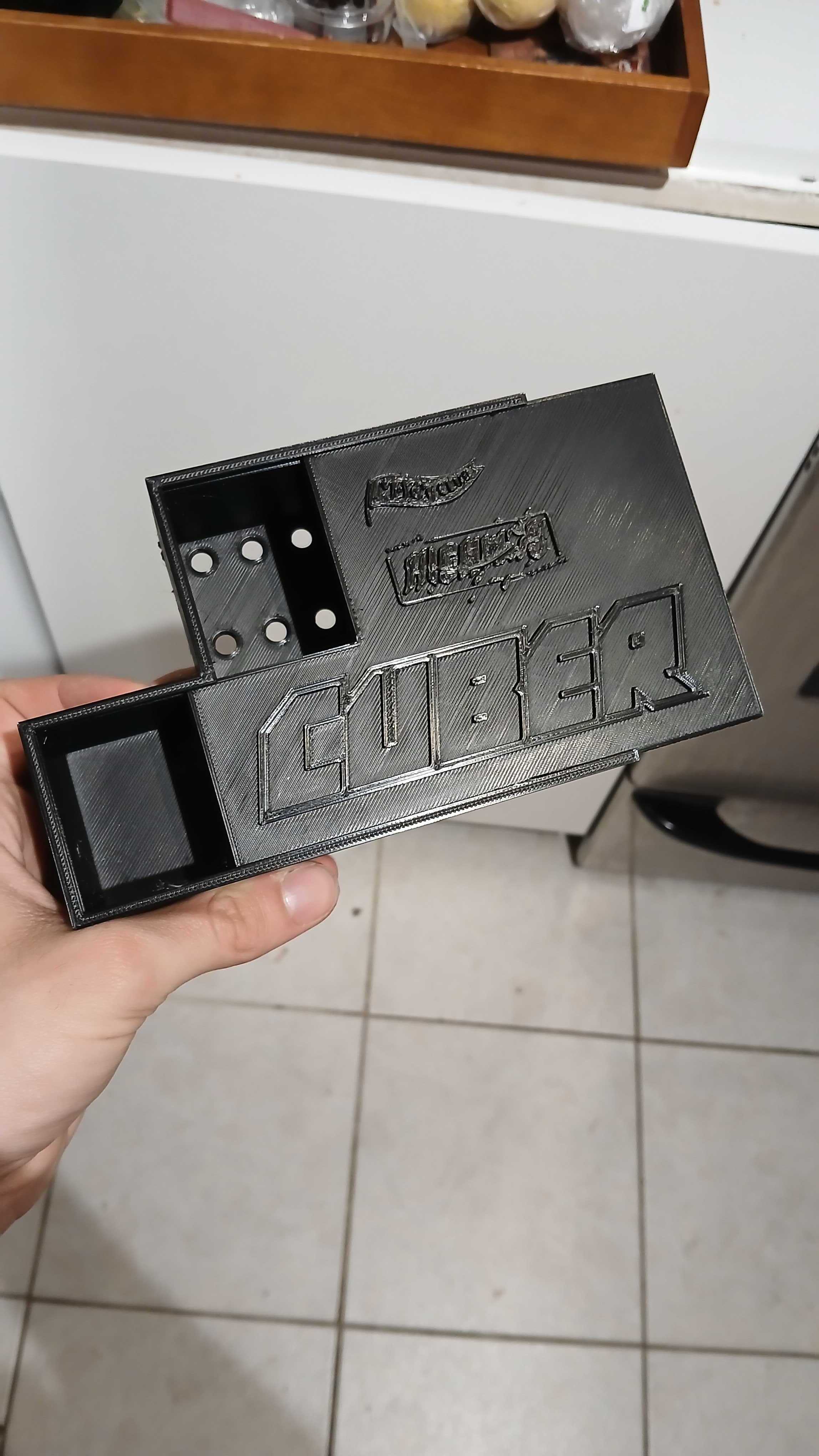
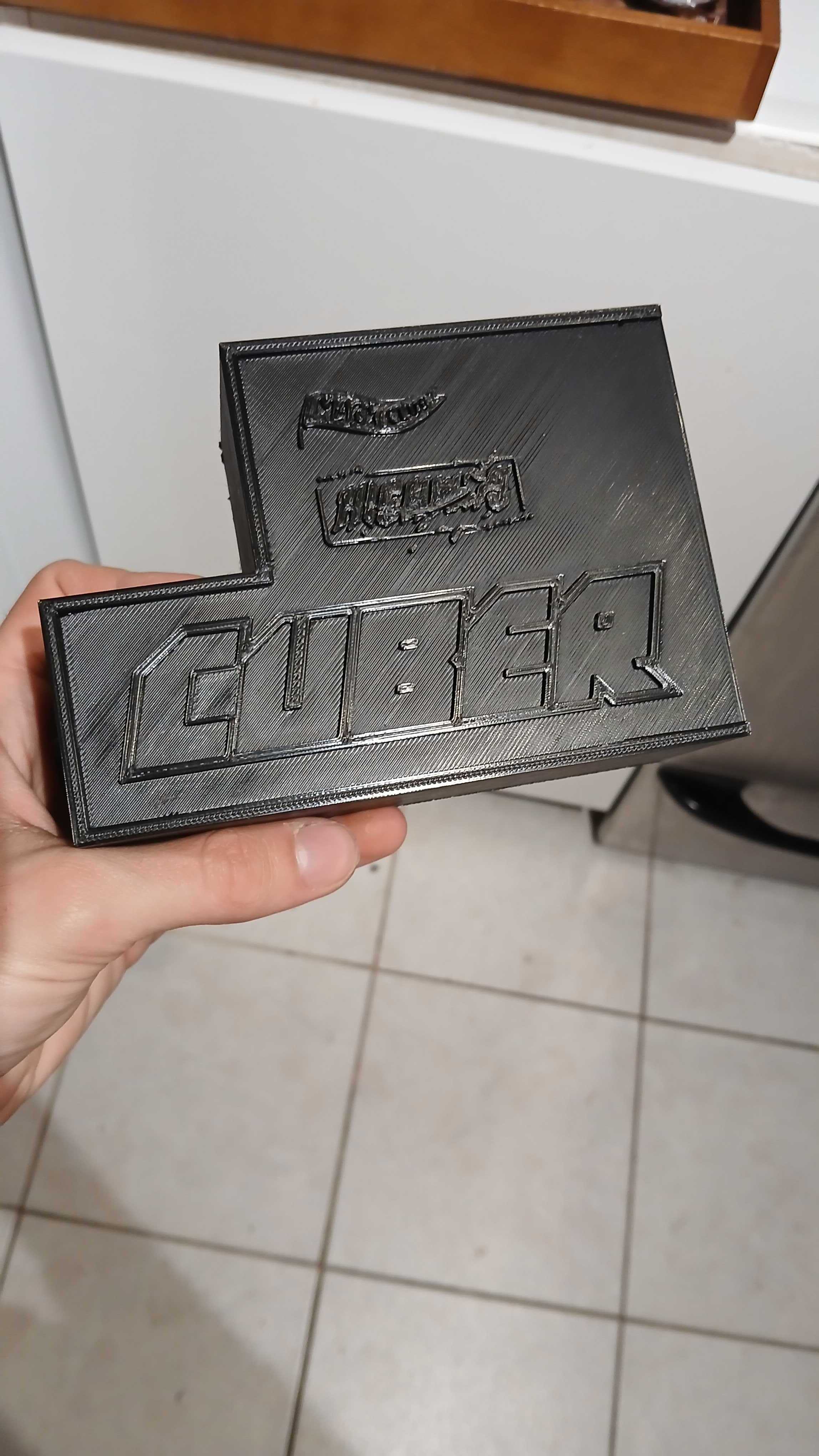
Bought more jumpers and extended all of my cables! I'm also gonna hide my wago wall of doom and despair in a cool looking box. I was able to print the lid today.
Time today: 4 hours
Time total: 86 hours
July 29th
Printed the box! Took 13 hours on my slow ahh printer but its done. Now I can finally do the finished wiring. I also polished the CAD a bit by modelling the fasteners and electronics.
Time today: 2 hours
Time total: 88 hours
July 30th
Completed the finalized wiring. I somehow keep doing this thing to myself where I try to shove a bunch of electronics into a container that's too small for them.
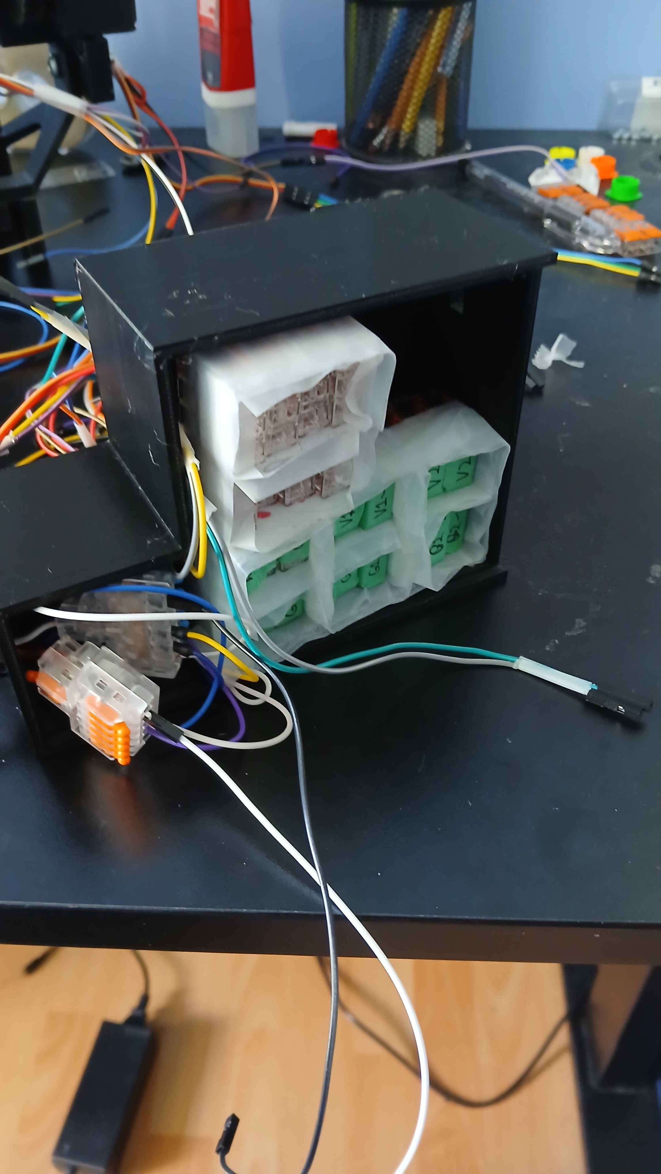
I then had to do a bunch of cable management.
Before vs. Before
(not a typo)
So what did I learn from this? I fucking suck at critical thinking. I made holes in the box for each type of wire, when it would have been smarter to make 6 holes for the 6 modules, and route the wires internally. That way I wouldn't have to worry about the mess on the outside, all of the wires to a module would go to the same place, and I could thread wires one by one to avoid mixups. Next time I do a project with similar wire requirements, I'll probably make a pcb, and follow this module.
On another note, I have thought about making a Cuber v2! If I did I would definitely use a PCB for wire distribution and use stronger motors. I'd like to beat the human wr (3.08s).
Anyways that's chill. Now I can focus on calibrating the colour sensors.
Time today: 6 hours
Time total: 94 hours
August 1st
Yo so the colour sensor calibrations work, but it all breaks down when doing individual squares as light from the adjacent squares bleeds into it. I create a kind of nozzle that would focus it onto a tiny spot. It improves it a lot, but it isn't quite there. It had a 9mm hole so I scaled it down to 5mm and printed it. Tomorrow I'll test it out.
FYI I have created a self-imposed deadling of this Sunday (August 3rd) to make the colour sensors work. Past that I will give up and create an easy routing for manually inputting the colours.
Time today: 3 hours
Time total: 97 hours
August 2nd
The new nozzle works! It's really consistent. It does reduce the light coming into the sensor a lot, but that doesn't affect it due to the normalization. I wrote a quick one-sided detection routine and calibrated three sides of the cube (top, front, and right). Calibrating it takes so much goddamn time. Still got the other half to do.
Hit the 100 hour mark though!
https://github.com/user-attachments/assets/758a44dc-87e6-4893-bd0c-782bb4a80f7b
Time today: 7 hours
Time total: 104 hours
August 3rd
Got ragebaited by this sensor. I just could not get it to tell apart white and yellow. That's when it hit me: I don't need all 6 sensors. I could get away with 3 and move the squares on other faces into their paths.
Time today: 4 hours
Time total: 108 hours
August 5th
Was still getting ragebaited by this sensor. I deduced that for some reason it wasn't picking up the blue frequency of light properly. I was able to calibrate the remaining two sensors though.
I ended up just writing an algorithm to detect the squares on the back face by moving them to the top and right faces for detection.
I also had some shoddy wiring on the front sensor, but I could not for the life of me figure it out, so I used the same method for it as well.
I had an issue with the power supply to the left face motor, so I disconnected it and spliced it into the right face motor :/
A lot of issues, however I got full colour detection and solving working! Sometimes it fails to pick up colours, so I put a manual input that would catch those and ask you for the colour after the routine is done.
Right now it's just optimization of the solving. Aiming for sub 10, will be happy with sub 15.
Video of first colour detection + solve (on the slack): https://hackclub.slack.com/files/U06SYK3M62J/F0994RHQTKL/20250805_202403.mp4
Time today: 8 hours
Time total: 116 hours
August 7th
Spent the day cleaning up the repo, and writing documentation.
I also created a pretty sick youtube video.